© 2018, IRJET | Impact Factor value: 6.171 | ISO 9001:2008 Certified Journal | Page 1350
Note to Coin Converter
Mayuri Sewatkar
1, Prof. Ajitkumar Khachane
21Mayuri Sewatkar, Department of Information Technology, Vidyalankar Institute of Technology, Mumbai, India
2Prof. Ajitkumar Khachane, Department of Information Technology, Vidyalankar Institute of Technology,
Mumbai, India
---***---Abstract -
Requirement of coins in a day to day transaction at places like a bus station, railway station, mall, and park is the main motive of designing an efficient and simple machine which will fulfill the need of coins for transactions so that people will not face the problem of coins.The basic concept is to provide coins in exchange of note, for this purpose we have to develop a mechanical coin dispensing model which takes the note inside and checks whether the note is fake or real, if the note is real, the camera takes pictures of it. After that, it will find out its value using image processing technique and then according to the value equivalent number of coins are dispensed. In this way, we could design an efficient machine which will be having a low production cost as compared to other existing machines. The idea is to implement a fake note detection unit using UV LED and a photodiode.
Key Words: Fake Note Detection, UV LED, Image
Processing, Photodiode, Coin Dispensing, MATLAB Processing.
1. INTRODUCTION
In today’s world, by now a note to coin converter is being used in various countries including India, but in India, such systems are scarce and very few people know about it and also their availability is limited to a few banks, but not at public places where it is needed more.
So, my idea is to implement such systems at public places which are smaller, lighter and does not require supervision.
The main aim of the project is to detect if the note is real or fake and then identify which note is placed in the machine with the help of image processing.
If the note is real, the camera takes pictures of it and finds out its value using image processing and then accordingly the coin dispensing machine gives an equivalent number of coins.
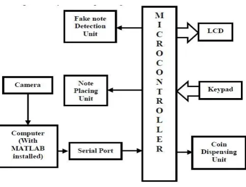
For detecting the note denomination, the MATLAB algorithm runs and the result is given to the controller which will manipulate the coin container through relays and motors, the user simply presses the keypad for which type of change he wants whether one rupee or five rupees or mixed and hence in the output we get coins as user requirement only if sufficient amount of coins are available to be dispensed, else
it will display insufficient amount of coins available and eject the note.
If the note is fake, the machine will eject the note displaying error.
Fig-1 :Block Diagram
2. IMAGE PROCESSING
Image processing is any form of processing for which the input is an image or a series of images or videos, such as photographs or frames of video. The output of image processing can either be an image or a set of characteristics or parameters related to the image.
It also means "Analyzing and manipulating images with a computer".
Image processing is performed in these three steps: First, import images with an optical device like a camera or a scanner or directly through digital processing.
Second, analyze or manipulate the images in some way. This step can include data summary and image improvement, or the images are analyzed to find rules that are not seen by the human eyes. For example, meteorologists use this processing to analyze satellite photographs.
[image:1.595.311.553.251.435.2]© 2018, IRJET | Impact Factor value: 6.171 | ISO 9001:2008 Certified Journal | Page 1351 Image processing usually means "digital" image processing,
but optical and analog image processing are also included in image processing.
An object in image processing is an identifiable portion of an image that can be interpreted as a single unit.
2.1 Digital Image Processing
Digital image processing is the use of computer algorithms to perform image processing on digital images. As a subcategory or field of digital signal processing, digital image processing has many advantages over analog image processing. It allows a much wider range of algorithms to be applied to the input data and can avoid problems such as the build-up of noise and signal distortion during processing. Since images are defined over two dimensions (perhaps more) digital image processing may be modeled in the form of multidimensional systems.
Digital image processing allows the use of much more complex algorithms, and hence, can offer both more sophisticated performance at simple tasks, and the implementation of methods which would be impossible by analog means.
In particular, digital image processing is the only practical technology for:
• Classification • Feature extraction • Multi-scale signal analysis • Pattern recognition • Projection
Some techniques which are used in digital image processing include:
• Anisotropic diffusion • Hidden Markov models • Image editing
• Image restoration
• Independent component analysis • Linear filtering
• Neural networks
• Partial differential equations • Principal components analysis • Self-organizing maps
• Wavelets
2.2 Analog Image Processing
Analog image processing is an image processing task conducted on two-dimensional analog signals by analog means (as opposed to digital image processing). Basically, any data can be represented in two types named as 1. Analog 2. Digital. If the pictorial representation of the data represented is in analog wave formats then that picture can be named as an analog image. E.g.: television broadcasting in older days. through the dish antenna systems. Whereas the digital representation or storing the data in digital form is termed as a digital image processing E.g.: image data stored in digital logic gates.
Fig-2:Analog VS Digital Image
3. FAKE NOTE DETECTION
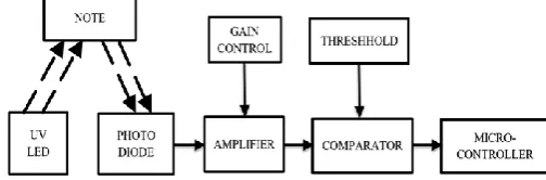
The Indian currency note has a speciality of absorbing the UV light and a fake note reflects the UV light. Fake note detection unit consists of comparator, UV LED, amplifier, and a photodiode.
[image:2.595.307.559.263.411.2]The UV LED source transmits the UV rays, if the note is fake then the all rays will be reflected back towards the photodiode and if the note is real it will absorb some amount of UV rays. This output of the UV Photodiode is given to amplifier. This output is amplified and then given to comparator. The threshold voltage is applied to the comparator. According to threshold voltage output of the comparator is then given to the microcontroller for further processing.
[image:2.595.305.557.645.728.2]© 2018, IRJET | Impact Factor value: 6.171 | ISO 9001:2008 Certified Journal | Page 1352
4. COLOR MODELS
Color models provide a standard way to specify a particular color, by defining a 3D coordinate system, and a subspace that contains all constructible colors within a particular model. Any color that can be specified using a model will correspond to a single point within the subspace it defines. Each color model is oriented towards either specific hardware (RGB, CMY, YIQ), or image processing applications (HSI).
1. The RGB Model
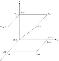
In the RGB model, an image consists of three independent image planes, one in each of the primary colors: red, green and blue. Specifying a particular color is by specifying the amount of each of the primary components present.
Fig-4: Geometry of the RGB color model using a Cartesian coordinate system
The figure shows the geometry of the RGB color model for specifying colors using a Cartesian coordinate system. The greyscale spectrum, i.e. those colors made from equal amounts of each primary, lies on the line joining the black and white vertices.
2. The HSI Model
Color’s are specified by three quantities hue, saturation, and intensity. This is the HSI model, and the entire space of colors that may be specified in this way is shown in the figure.
Fig-5: The HSI Solid Model
Fig-6: The HSI Triangle Model
The figure shows the HSI solid on the top and the HSI triangle at the bottom, formed by taking a horizontal slice through the HSI solid at a particular intensity. Saturation is given by distance from the axis and Hue is measured from red. Colors on the surface of the solid are fully saturated, i.e. pure colors, and the grayscale spectrum is on the axis of the solid. For these colors, hue is undefined. Conversion between the RGB model and the HSI model is quite complicated.
[image:3.595.175.542.65.590.2] [image:3.595.309.556.105.527.2] [image:3.595.37.289.288.551.2]© 2018, IRJET | Impact Factor value: 6.171 | ISO 9001:2008 Certified Journal | Page 1353
5. ALGORITHM
1. Initialize.
2. Set threshold “the”.
3. Set COM port for serial communication.
4. Now fake note detection circuit will check the fake note.
5. If 1 is received from fake note detection circuit then the note will be given out.
6. If 0 is received controller will send “*” to the serial port.
7. Wait for “*” to be received on serial port from the microcontroller.
8. When arrives, get a snapshot of note by using the camera.
9. Convert RGB image from the camera to HSI image. 10. Separate “S” plane image from HSI image.
11. Cropping the image:
1. Top and Bottom by 40 pixels 2. Left and Right by 50 pixels.
12. Set threshold “m” for Binarization of the image. 13. Binarize the image.
1. If above “m”, store 1 in the image matrix. 2. If below “m”, store 0 in the image matrix. 14. Calculate the percentage of 1 present in the image
matrix.
15. If the percentage of 1 is more than threshold “th”, send “2” on the serial port as a denomination for Rs 20.
16. Else Send “1” on serial port as denomination for Rs10.
17. Go to Step 3 until counter becomes full. 18. Set coin counter as per stack of Rs 1 and Rs 5. 19. Wait for “eject” key to be pressed.
20. When eject key is pressed motor actuates and the tray comes out.
21. Then MATLAB code is executed to check denomination.
22. If 1 is received by the controller from PC, the controller waits for the choice of coins entered by the user.
23. Same if 2 is received.
24. The controller checks coin counter which indicates coin sufficiency.
25. If coins are sufficient then motor rotates as per choice entered which dispenses the coins else displays insufficient coins and eject the note. 26. After dispensing of coins motor actuates to drop the
note inside the machine and goes to Step 1.
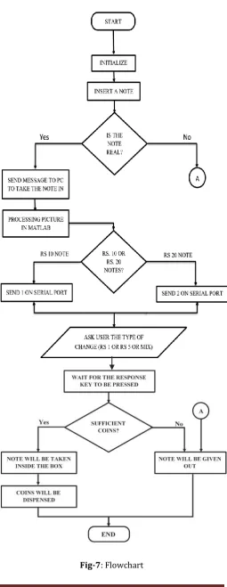
6. FLOWCHART
[image:4.595.308.564.105.766.2]© 2018, IRJET | Impact Factor value: 6.171 | ISO 9001:2008 Certified Journal | Page 1354
7. MATLAB PROCESSING
1. As „*‟ is received on serial port MATLAB started its processing and takes picture of note by a camera connected to the computer.
2. The original image taken in RGB format is converted into HSI image format.
3. S-Plane image is extracted from HSI image format for calculation and threshold purpose.
4. Then according to MATLAB coding, Output is generated and sent to the serial port.
8. ADVANTAGES OF THIS SYSTEM
1. Ease of change availability. 2. Fake Note’s won’t be accepted.
3. Coin’s will be dispensed from user’s perspective.
9. CONCLUSIONS
I can develop an interactive system that generates currency recognition system using image processing with the help of MATLAB and a mechanical dispenser machine that would give coins in exchange for the notes.
In future, we could add many new functions according to the availability and conditions.
This concept suggests an interactive system that generates currency recognition system using color model and binarization technique with the help of MATLAB.
The system adopts the interactive techniques of image binarization using specific threshold depending upon surrounding environment and allows the user to identify the currency denomination.
Thus, we can develop an interactive system that generates currency recognition system using image processing with the help of MATLAB. In day to day life, we are suffering for a change of currency at many public places, so this system which is a real-time application for all real-time places i.e. in the buses, railway station, malls could prove useful for all people around the world.
In future, we can make many enhancements in this machine like we could add many new functions according to the availability and conditions. We could even add the note denominations and coin denominations according to the user feasibility that could be convenient for the people as well as the government.
These kinds of machines could be made available in public places like parks, railway stations, bus stands, mall’s, etc.
ACKNOWLEDGMENT
I am extremely grateful to Dr. S. A. Patekar, Principal, Vidyalankar Institute of Technology and Dr. Meenakshi Arya, Head of Department, Department of Information Technology, for providing all the required resources.
© 2018, IRJET | Impact Factor value: 6.171 | ISO 9001:2008 Certified Journal | Page 1355 I am very much thankful to my parents who guided me in
every step which I took.
REFERENCES
[1] International Journal of Scientific & Engineering
Research, Volume 7, Issue 2, February-2016 ISSN 2229-5518 “Intelligent Indian Currency Detection with Note to Coin Exchanger”
[2] International Journal of Modern Trends in Engineering
and Research; e-ISSN No.:2349-9745, “Counterfeit Currency Recognition Using SVM With Note to Coin Exchanger”
[3] International Journal on Recent and Innovation Trends
in Computing and Communication ISSN 2321 – 8169 Volume: 1 Issue: 3 154 – 158 IJRITCC | MAR 2013 “NOTE TO COIN EXCHANGER USING IMAGE PROCESSING”
[4] International Journal of Advanced Research in Computer
Engineering & Technology (IJARCET) Volume 5 Issue 3, March 2016 “Note to Coin Exchanger”
[5] International Journal on Recent and Innovation Trends
in Computing and Communication ISSN: 2321-8169 Volume: 2 Issue: 4 942 – 946 “Intelligent Note to Coin Exchanger with Fake Note Detection”
BIOGRAPHIES
Mayuri Sewatkar
Department of Information Technology
Vidyalankar Institute of Technology
Mumbai, India
Prof. Ajitkumar Khachane Department of Information Technology
Vidyalankar Institute of Technology
Mumbai, India