© 2017 IJSRST | Volume 3 | Issue 1 | Print ISSN: 2395-6011 | Online ISSN: 2395-602X Themed Section: Science and Technology
Finite Element Analysis of Reinforced Concrete Flat Plates
A Comprehensive Study
Madhavi R.V
1, N. Siva Shenkar Reddy
21
P. G. Student, Department of Civil Engineering, Sir Vishveshwaraiah Institute of Science and Technology, Madanapalle, Andhra Pradesh, India
2
Associate Professor, HOD, Department of Civil Engineering, Sir Vishveshwaraiah Institute of Science and Technology, Madanapalle, Andhra Pradesh, India
ABSTRACT
For many years, researchers have been working toward the successful application of finite element technology to the design of reinforced concrete flat plate systems due to practical restrictions inherent in simplified or approximate design techniques. Flat plates are slabs of uniform thickness which are directly supported on columns without use of beams. Flat plates are to be designed for the positive and negative bending moments in the column strip and middle strips. The slab is to be designed with adequate safety margin against punching shear. Flat plates can be designed as waffle slabs by removing concrete in the tension zone and placing the steel reinforcement in the form of groups of bars at intervals equal to the grid size. This arrangement leads to saving of material and reduction in self-weight. Flat plates provide satisfactory floors for panels with adequate headroom due to absence of beams, column capitals or drop. However, in the case of exterior panels, edge beams will be necessary.
Keywords : Flat slab, FEM, waffle slab
I.
INTRODUCTION
The purpose of this study was the implementation and verification of a procedure in SAFE to Analysis of reinforced concrete flat plate systems based on the results of finite element analysis.
Flat Plate Systems
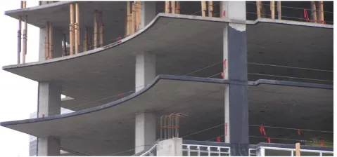
Flat plates are widely used in multi-storey structures such as office buildings and car parking. A flat plate structure is composed of slabs and columns only, interconnected as shown in Figure 1.
The foremost advantage of the flat plate structure over other types of structures is that the elimination of beams and girders reduces overall floor depth, thereby creating additional floor space for a given building height.
Figure 1 : Flat Plate Reinforced Concrete Structure
In general, the flat plate system may be of one of the three categories, as illustrated in Figure 1
a) Standard construction where exterior columns are located at the edge of the slabs;
b) Band-beam slabs where the portion of the slab along the column line is thickened in one direction or the other. This is coupled with a thickness reduction at the remaining portions of the slab; and,
a)Standard b)Band-beam c)Flat plate with
Figure 2. Flat plate category
II.
METHODS AND MATERIAL
2. Literature Review
2.1 Punching Shear Failure Mechanisms and
Patterns
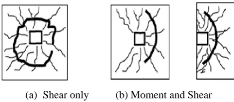
Punching shear failure normally occurs around a column or a concentrated load on a slab. It is associated with a particular collapse mechanism in which a conical plug of concrete suddenly perforates the slab above the column (Menetrey, 2002).
(a) Shear only (b) Moment and Shear
Figure 2: Typical Punching Shear Failures
2.2 Modeling of Slabs Using Finite Elements
2.2.1 General Modeling Requirements
The finite element method is an approximate technique, and as such, results computed using the finite element method must be critically evaluated before relied upon in a design application. This process of critical evaluation involves several steps for any structure being analyzed. The number of elements used in a model can greatly affect the accuracy of the solution. In general, as the number of elements, or the fineness of the mesh, is increased, the accuracy of the model increases as well. As multiple models are created with an increasingly finer mesh, the results should converge to the correct numerical solution such that a significant increase in the number of elements produces an insignificant change in a particular response quantity. Not all response quantities will converge at the same rate, however.
Displacements will generally be the most accurate response quantity computed and will converge faster than stresses, with the exception of some elements derived with hybrid stress formulations, in which case the stresses can converge at the same rate or higher than the displacements.
2.2.2 Assumptions for R.C. Flat Plates in Finite
Element Analysis
The type of analysis applied in this study is a linear elastic analysis. Reinforced concrete is a highly nonlinear material made up of many elastic, brittle materials, the stress-strain curve of concrete indicates some degree of ductility. Concrete begins cracking at a tensile stress of approximately 8 to 15% of its compressive strength. At the ultimate level, IS 456:2000 states that the maximum allowable strain at the extreme concrete compression fiber shall be assumed equal to 0.0035. This analysis assumes the gross section is resisting the applied loads at all stress levels, and that the stress-strain relationship is perfectly linear, even if the compressive strain in the concrete exceeds 0.003 or if the tensile stress at the location of the reinforcing bars exceeds the yield stress of the steel. it allows the application of a linear analysis that ignores geometric nonlinearity.
2.3 Finite Element Representation
The finite element analysis of a continuum starts with the subdivision of the physical system into an assemblage of discrete elements. The displacement vector {d} at any point within a particular structure is approximated by interpolating functions associated with generalized coordinates i d, which are the displacements of the nodes of the finite element discretization of the structure. For a finite element this approximation can be formally written as
1
1
...
... .
elei
i
d
d
N
d
N
N
d
(1)
displacements are known at any point within the element, the strains can be determined from the strain-displacement relation. In the discrete problem this can be formally written as
B
.
d
ele (2)The matrix [B] will be derived later for beams and slabs separately. The stresses can now be determined from the material constitutive law
D
.
o
o (3)where [D] is the element material matrix, {o} is the initial strain vector and {o } is the initial stress vector. By applying the virtual work principle or the theorem of minimum potential energy to the assemblage of discrete elements the following equilibrium equations result
0 0
.
g0
K
d
F
F
F
R
(4) The terms in Eq. 3.4 are derived as follows:
the stiffness matrix [K],
T.
.
ele
K
B
D
B dV
(5)the nodal forces due to surface traction,
T.
p
ele
F
N
p dV
(6)the nodal forces due to body forces,
T.
g
ele
F
N
g dV
(7)the nodal forces due to initial strains,
.
o
T
o ele
F
B
D
dV
(8)the nodal forces due to initial stresses,
.
o
T
o ele
F
B
D
dV
(9)In Eqs. 4 - 9 {d} is the vector of node displacements, {R} is the vector of applied nodal forces, {p}is the vector of surface forces and {g} is the vector of body forces.The node displacements {d} can be determined from the solution of the
system of simultaneous algebraic equations in Eq. 4, whereupon the strains and stresses at any point of the structure can be obtained from Eqs. 2 and 3. In a
nonlinear problem the stiffness matrix [K] depends on the displacement vector {d} and the nonlinear system of algebraic equations in Eq. 4.
2.4 Numerical Implementation
2.4.1 Iteration Method
The numerical implementation of the finite element model requires the solution of Eq.
.
0o o
p g
K d F F F F R
This is a system of simultaneous nonlinear equations, since the stiffness matrix K, in general, depends on the displacement vector d. The solution of this system of nonlinear equations is typically accomplished with an iterative method. The load vector Ris subdivided into a number of sufficiently small load increments, which are successively applied (Fig. 3.4).
F
F3
F2
F1
0 r
F4
Actual Numerical
Figure 3. Incremental Load Method without Correction
2.5 Design Strips For Flat Plates
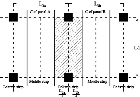
a) Col umn stri p - Column strip means a design strip having a width of 0.25 l2, but not greater than 0.25 l1 on each side of the column centreline, where
l1 is the span in the direction moments are being determined, measured centre to centre of supports and l2 is the-span transverse to l1, measured centre to centre of supports.
b) Mi ddl e st ri p - Middle strip means a design strip
bounded on each of its opposite sides by the column strip.
c) P anel - Panel means that part of a slab bounded
on-each of its four sides by the centre-line of a column or centre-lines of adjacent-spans.
III.
RESULTS AND DISCUSSION
In order to demonstrate the convergence of a flat plate system, a square 6.1 m x 6.1 m, fix-supported flat plate was modeled. The geometry of this system is shown in Figure 4. The slab was 150 mm thick and was composed of M20 concrete. The slab was subjected to its own self-weight as well as a 2.4 KN/m2 live load.The slab was analyzed using four different models, each with an increasing number of finite elements. Each of these models is shown in Figure 5. The four meshes contained 16 elements (4x4 mesh), 64 elements (8x8 mesh), 256 elements (16x16 mesh), and 1024 elements (32x32 mesh), respectively. Fixed support conditions were achieved by restraining all translations and rotations for the joints along the boundaries.
6.1 m
6.1 m
X Y
Figure 4. Geometry of Flat Plate Model
Figure 5. Finite Element Mesh Models
Table 1. Comparison of SAFE Results with GT
STRUDL*
Element Mesh Displacement (mm)
Design Moment
(KN-m)
As, Required
(mm2)
GT STRUDL
16 -15.73 99.41 147.72
64 -14.71 117.15 174.43
256 -14.40 121.48 180.93
1024 -14.33 122.51 182.55
SAFE
16 -14.01 101.08 150.27
64 -14.02 115.85 172.34
256 -14.31 121.14 180.46
1024 -14.33 122.48 182.32
*Note : GT STRUDL results as referred by James B.
0 200 400 600 800 1000 -2
0 2 4 6 8 10
% Dif
fe
r
e
n
c
e
Disp
lac
e
m
e
n
t (
m
m
)
No. of Elements
GT STRUDL SAFE
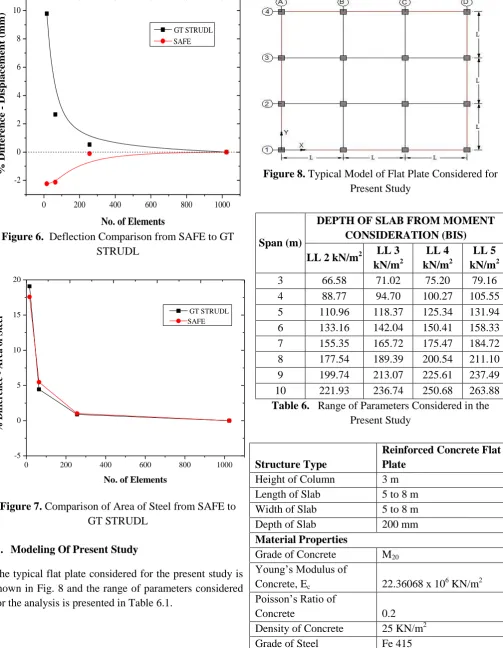
Figure 6. Deflection Comparison from SAFE to GT
STRUDL
0 200 400 600 800 1000 -5
0 5 10 15 20
% Diff
er
en
ce
- A
re
a of Ste
el
No. of Elements
GT STRUDL SAFE
Figure 7. Comparison of Area of Steel from SAFE to
GT STRUDL
A. Modeling Of Present Study
The typical flat plate considered for the present study is shown in Fig. 8 and the range of parameters considered for the analysis is presented in Table 6.1.
Figure 8. Typical Model of Flat Plate Considered for
Present Study
Table 6. Range of Parameters Considered in the
Present Study
Structure Type
Reinforced Concrete Flat Plate
Height of Column 3 m Length of Slab 5 to 8 m Width of Slab 5 to 8 m Depth of Slab 200 mm
Material Properties
Grade of Concrete M20 Young’s Modulus of
Concrete, Ec 22.36068 x 10 6
KN/m2 Poisson’s Ratio of
Concrete 0.2 Density of Concrete 25 KN/m2 Grade of Steel Fe 415
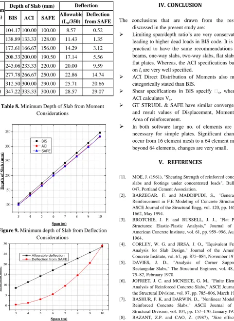
Table 7. Minimum Depth of Slab from Deflection
Considerations
Span (m)
DEPTH OF SLAB FROM MOMENT CONSIDERATION (BIS)
LL 2 kN/m2 LL 3
kN/m2
LL 4
kN/m2
LL 5
kN/m2
Span (m)
Depth of Slab (mm) Deflection
BIS ACI SAFE Allowable
(Ln/350)
Deflection from SAFE
3 104.17 100.00 100.00 8.57 0.52 4 138.89 133.33 128.00 11.43 1.35 5 173.61 166.67 156.00 14.29 3.12 6 208.33 200.00 190.50 17.14 5.56 7 243.06 233.33 220.00 20.00 9.59 8 277.78 266.67 250.00 22.86 14.74 9 312.50 300.00 290.00 25.71 20.66 10 347.22 333.33 300.00 28.57 29.07
Table 8. Minimum Depth of Slab from Moment
Considerations
3 4 5 6 7 8 9 10
100 150 200 250 300 350
D
ept
h of
Sl
ab (
m
m
)
Span (m)
BIS ACI SAFE
Figure 9. Minimum depth of Slab from Deflection
Considerations
3 4 5 6 7 8 9 10
0 5 10 15 20 25 30
D
efl
ecti
on (
m
m
)
Span (m)
Allowable deflection Deflection from SAFE
Figure 10. Deflection Comparison for SAFE with
Allowable Deflection
IV.
CONCLUSION
The conclusions that are drawn from the results discussed in the present study are:
Limiting span/depth ratio’s are very conservative leading to higher dead loads in BIS code. It is not practical to have the same recommendations for beams, one-way slabs, two-way slabs, flat slabs & flat plates. Whereas, the ACI specifications based on lnare very well specified.
ACI Direct Distribution of Moments also more categorically stated than BIS.
c, whereas
ACI calculates Vc.
GT STRUDL & SAFE have similar convergence and result values of Displacement, Moment & Area of reinforcement.
In both software large no. of elements are not necessary for simple plates. Significant changes occur from 16 element mesh to a 64 element mesh, beyond 64 elements, changes are very small.V.
REFERENCES
[1]. MOE, J. (1961), "Shearing Strength of reinforced concrete
slabs and footings under concentrated loads", Bulletin 047, Portland Cement Association.
[2]. BARZEGAR, F. and MADDIPUDI, S., "Generating
Reinforcement in F.E Modeling of Concrete Structures," ASCE Journal of the Structural Engg, vol. 120, pp. 1656 – 1662, May 1994.
[3]. BROTCHIE, J. F. and RUSSELL, J. J., "Flat Plate
Structures: Elastic-Plastic Analysis," Journal of the American Concrete Institute, vol. 61, pp. 959–996, August 1964.
[4]. CORLEY, W. G. and JIRSA, J. O., "Equivalent Frame
Analysis for Slab Design," Journal of the American Concrete Institute, vol. 67, pp. 875–884, November 1970.
[5]. DAVIES, J. D., "Analysis of Corner Supported
Rectangular Slabs," The Structural Engineer, vol. 48, pp. 75–82, February 1970.
[6]. JOFRIET, J. C. and MCNEICE, G. M., "Finite Element
Analysis of Reinforced Concrete Slabs," ASCE Journal of the Structural Division, vol. 97, pp. 785–806, March 1971.
[7]. BASHUR, F. K. and DARWIN, D., "Nonlinear Model for
Reinforced Concrete Slabs," ASCE Journal of the Structural Division, vol. 104, pp. 157–170, January 1978.
[8]. BAZANT, Z.P. and CAO, Z. (1987), "Size effect in