An Exergy Analysis of Duct able with Twin
Compressor and Single Fan Packaged Air
Conditioning System to Improve its Coefficient
of Performance
Hiren K. Bapodara Jaspal B. Dabhi
ME Scholar Assistant Professor
L.D.R.P-ITR, Gandhinagar L.D.R.P-ITR, Gandhinagar
Abstract
Air-conditioning system is now a day more in use as due to the high rise in global temperature because of global warming and so in parallel the energy required and energy utilized is also a subject to be focused upon. As energy and exergy are directly related to the economic development of the nation. Exergy is an indicator which shows that which shows where system needs improvement in order to improve the overall efficiency. This paper presents in detail about the exergy analysis of packaged air conditioning system in a room with gathering of people at different time interval and varying atmospheric conditions. And thus which can lead towards the improvement in the particular component’s efficiency. The changes taking place at various time intervals are shown by graphs. At heat temperature and at which component the exergy destruction takes place maximum and minimum is shown here. Keywords: Energy, Entropy Exergy, Exergy destruction
________________________________________________________________________________________________________
I. INTRODUCTION
Packaged air conditioning systems as its name itself suggest its meaning as consist of packaged form structure i.e. a closed structure in which all the components assembled, off-the-shelf equipment that provides space heating, cooling, and ventilation smaller and medium spaces. These systems are having the capacities from 5 TR to 100 TR. Small capacity units of room air conditioning systems are without duct while larger package units are having ductwork for air distribution. As more the tonnage, the more will be the airflow and thus it requires ductwork to cover all spaces and to minimize noise. Thus It is a house in which the entire refrigeration in a single package and may also include heating coils along with the evaporator. The condenser used in these systems could be either air cooled or water cooled.
Here An experiment is carried out by switching on the 11TR system having R22 Refrigerant and doing the analysis at different time intervals and thus various values at all the different temperature of inlet and outlet are calculated and out of which it is tried to find out where there is maximum exergy destruction and at which part there is need of amendments so as to improve overall coefficient of performance
II. EXERGY
Exergy analysis is used because of its advantage over the conventional heat balance method used for design purpose and performance analysis of systems related to energy. It provides a more accurate measurement of the actual inefficiencies in the system and the true location of these in efficiencies. In refrigeration cycle, with the heat balance analysis, it is not possible to find out the true losses. Exergy analysis is based on the assumption that there is an infinite equilibrium environment that ultimately surrounds all systems that are to be analyzed. The exergy or available energy of a system is the maximum work that could be derived if the system were allowed to come to equilibrium with the environment. It is a consequence of the second law of thermodynamics that the combined exergy of all systems can only decrease or remain unchanged. Unlike energy, exergy is not conserved, once it is lost, it is lost forever. In other words, exergy (quality) is degradable, while energy (quantity) is conserved. Exergy can be exchanged between systems, but if there are thermodynamic irreversibility’s such as, friction or heat transfer with finite temperature differences, some of the potential for the production of work is destroyed. In all real processes, therefore, the total exergy of the system decreases [1-5].
Exergy Analysis:
(IJSTE/ Volume 2 / Issue 10 / 147)
the environment consists of the local surroundings of the compressor. These local surroundings are modeled as being in equilibrium and infinite. Given sufficient information, the exergy of all the systems can be determined at any time. On the basis of first law, the performance of refrigeration cycle is based on the coefficient of performance, which is defined as the ratio of net refrigerating effect (cooling/heating load) obtained per unit of power consumed.[6]
Energy and exergy analyses need some mathematical formulations for the simple vapor compression refrigeration cycle. In the vapor compression system, there are four major components: evaporator, compressor, condenser, and expansion valve. External energy (power) is supplied to the compressor and heat is added to the system in the evaporator, whereas in the condenser heat rejection is occurred from the system. Heat rejection and heat addition are dissimilar to different refrigerants, which cause a change in energy efficiency for the systems. Exergy losses in various components of the system are not same. A temperature and pressure are denoted by T0 and P0, respectively. Exergy is consumed or destroyed due to entropy created depending on the associated processes [7].
Mathematical formulation for exergy analysis in different components can be arranged in the following way Specific exergy in any state[8],
as
COP=Qe/Wc
Exergy balance for a control volume can be expressed as [2]
EX D = ∑(mex)in − ∑(mex)out [∑(Q(1 − T0 / T )in− ∑(Q(1 − To / T )out ] ∑W (1) For the present system shown in Fig.4.1b,
the component wise exergy balance equation can be written as below:
1) Compressor
(EX D )comp =Ex1 + Wc − Ex 2 = mr (To (s2 − s1 )) (2) 2) Condenser
(EX D )cond = Ex 2 − Ex 3 = mr (h2 − To s2 ) − mr (h3 − To s3 ) (3) 3) Expansion Device:
(EX D )exp = Ex 3 − Ex 4 = mr (h3 − To s3 ) – mr (h4 − To s4 ) = mr (To (s2 − s1 )) 4) Evaporator
(EX D )evap = Ex 4 + Qe (1 − To / Tr )− Ex1= mr (h4 − To s4 ) + Qe (1 − To / Tr ) − mr (h1 − To s1 )
The total exergy destruction in the system is the sum of exergy destruction in different components of the system and is given by 5) Total exergy destruction
(EXD)total = (EXD)comp + (EXD)exp + (EXD)evap Exergy Efficiency
exergy = Qe/Wc (1 − T0 / Tr )[8]
III. EXPERIMENTAL SETUP
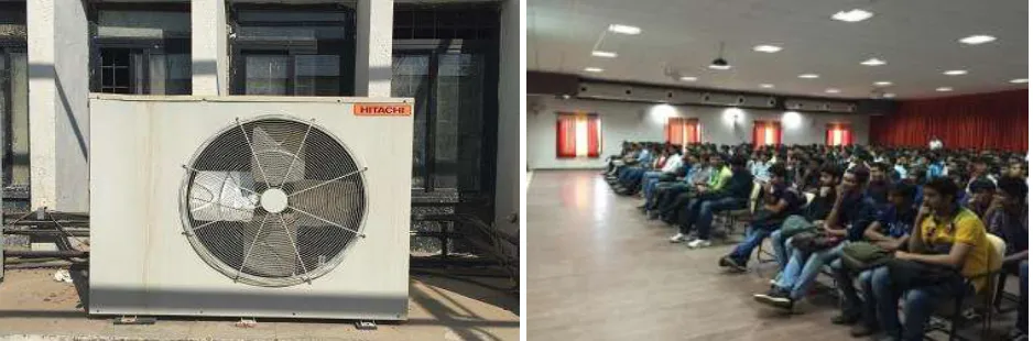
Packaged air conditioning systems(MODEL : 11.0 TR DUCTABLE WITH TWIN COMP & SINGLE FAN - PAG132ERD3 consist of pre-assembled, off-the-shelf equipment that provides space heating, cooling, and ventilation to small and medium spaces. This system is having capacity of 11 TR . Small capacity Individual room air conditioning systems are essentially ductless while larger package units use ductwork for air distribution. Obviously the larger the tonnage, the larger will be the airflow and it will require ductwork to cover all spaces and to reduce noise. It is also possible to house the entire refrigeration in a single package and may also include heating coils along with the evaporator as shown below
Fig. 1: Room where the the AC system is installed and Fig. 2: outside unit of Packaged AC experiment was carried out at various time interval
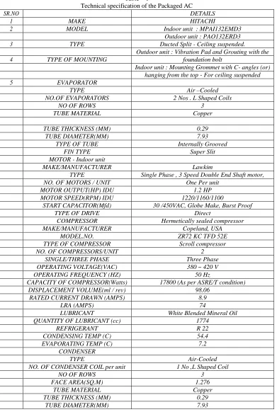
Table – 1
Technical specification of the Packaged AC
SR.NO DETAILS
1 MAKE HITACHI
2 MODEL Indoor unit : MPAI132EMD3
Outdoor unit : PAO132ERD3
3 TYPE Ducted Split - Ceiling suspended.
Outdoor unit : Vibration Pad and Grouting with the
4 TYPE OF MOUNTING foundation bolt
Indoor unit : Mounting Grommet with C- angles (or) hanging from the top - For ceiling suspended
5 EVAPORATOR
TYPE Air –Cooled
NO.OF EVAPORATORS 2 Nos . L Shaped Coils
NO OF ROWS 3
TUBE MATERIAL Copper
TUBE THICKNESS (MM) 0.29
TUBE DIAMETER(MM) 7.93
TYPE OF TUBE Internally Grooved
FIN TYPE Super Slit
MOTOR - Indoor unit
MAKE/MANUFACTURER Lawkim
TYPE Single Phase , 3 Speed Double End Shaft motor,
NO. OF MOTORS / UNIT One Per unit
MOTOR OUTPUT(HP) IDU 1.2 HP
MOTOR SPEED(RPM) IDU 1220/1160/1100
START CAPACITOR(Mfd) 30 /450VAC, Globe Make, Burst Proof
TYPE OF DRIVE Direct
COMPRESSOR Hermetically sealed compressor
MAKE/MANUFACTURER Copeland, USA
MODEL.NO. ZR72 KC TFD 52E
TYPE OF COMPRESSOR Scroll compressor
NO. OF COMPRESSORS/UNIT 2
SINGLE/THREE PHASE Three Phase
OPERATING VOLTAGE(VAC) 380 ~ 420 V
OPERATING FREQUENCY (HZ) 50 Hz
CAPACITY OF COMPRESSOR(Watts) 17800 (As per ASRE/T condition)
DISPLACEMENT VOLUME(ml / rev) 98.06
RATED CURRENT DRAWN (AMPS) 8.9
LRA (AMPS) 74
LUBRICANT White Blended Mineral Oil
QUANTITY OF LUBRICANT (cc) 1774
REFRIGERANT R 22
CONDENSING TEMP (C) 54.4
EVAPORATING TEMP (C) 7.2
CONDENSER
TYPE Air-Cooled
NO. OF CONDENSER COIL per unit 1 No ,L Shaped Coil
NO OF ROWS 3
FACE AREA(SQ.M) 1.276
TUBE MATERIAL Copper
TUBE THICKNESS (MM) 0.29
TUBE DIAMETER(MM) 7.93
IV. EXPERIMENTAL PROCEDURE
Experimental Procedure:
- Switch on the AC when the hall is fully loaded i.e when fully occupied by people
- Now with the use of digital thermometer take the tempreture reading at different time intervals
- Readings are taken at different interval of every five minutes for around 1 hours.
(IJSTE/ Volume 2 / Issue 10 / 147)
- Now from the value of this condensing and evaporating tempreture furether values of various enthalpies are found from the R22 table at those particular tempreture and pressure
- From the value of enthalpy and tempreture and pressure further exergy is caluted whose value is as shown in the table below
- Now, the conclusion is made from the table as shown in the result
V. RESULT AND DISCUSSION
Result Table – 1
Parameters at intervals of every 5 minutes Pdisch./ Psuc./ m/ Cond. Evap. Inlet/ Time kg/cm² kg/cm² kg/s In/°c °c
5 18.4 4.1 0.03767 73 10
10 18.5 4.2 0.03767 81 8
15 18.6 4.2 0.03767 81.5 7.5
20 18.2 4.11 0.03767 83 8
25 18.6 4.11 0.03767 83 8.1
30 18.7 4.11 0.03767 82 8
35 18.7 4.23 0.03767 84 7
40 18.7 4.26 0.03767 87 7.8
45 18.7 4.26 0.03767 87 8.5
50 18.9 4.27 0.03767 87 9
55 19.8 4.28 0.03767 87 6.8
60 18.5 4.28 0.03767 88 7.6
65 18.3 4.25 0.03767 81 7.6
Result Table – 2
Energetic performance results obtained from the values of result table 1
RE Wcomp./k EXD EXD EXD EXD EXD Exergy % Exergy
/kJ J COP evap. comp. cond. exp. Total Efficiency Efficiency
6.85 1.29 4.83 3.15 4.17 3.37 3.9 15.41 0.401 40.2
6.32 1.50 4.13 3.76 4.31 3.37 3.94 15.51 0.445 44.3
6.62 1.55 4.03 3.55 4.36 3.39 3.93 15.53 0.459 45.8
6.58 1.58 3.954 3.83 4.43 3.38 3.92 15.63 0.423 42.3
6.62 1.57 3.98 3.89 4.40 3.33 3.952 15.59 0.42 42.1
6.73 1.52 4.12 3.92 4.385 3.37 3.70 15.5 0.404 40.02 6.17 1.59 3.89 3.49 4.43 3.39 3.921 15.52 0.4440 44.6 6.62 1.78 3.50 3.90 4.578 3.30 3.86 15.756 0.435 43.07 6.28 1.76 3.52 3.88 4.58 3.38 3.81 15.77 0.414 41.61 6.83 1.74 3.54 3.92 4.566 3.297 3.87 15.743 0.396 39.46 6.02 1.75 3.52 3.47 4.54 3.24 3.96 15.62 0.443 44.58 6.66 1.80 3.47 3.64 4.60 3.28 3.81 15.75 0.436 43.54 6.66 1.55 4.02 3.84 4.39 3.35 3.43 15.62 0.436 43.54
VI. CONCLUSION
It is concluded from the above obtained data that exergy destruction is highest in compressor than comes condenser followed by expansion device and at last the evaporator So the main focus should be on the design parameters as well as the capacity of the compressor with which the efficiency can be improved. Other parameters such as friction loss, economizer arrangement, design and operation of condenser are also studied and necessary amendments in it can help improving the overall coefficient of performance.
VII.FUTURE SCOPE
Here the result obtains shows that at which particular component exergy destruction takes place and how much it accounts from overall exergy loss so from this it can be identified that which particular component needs improvement and thus further work can be done modification of component technically as well as non-technically to improve the overall coefficient of performance.
REFERENCES
[2] Tyagi, S.K., Park, S.R., Tyagi, V.V.,Anand, S., Second law based performance evaluation and parametric study of a sea water source cascade heat pump”,International Journal of Exergy, Vol. 7(3), (2010), pp.369–386.
[3] Tyagi, S.K., Kim, M.S., Park, S.R., Anand, S., Second law based performance of a modified VAC hybrid heat pump system using NH3-H2O as the working fluid”, Indian Journal of Pure & Applied Physics, Vol.48, (2010), pp.212-219.
[4] Tyagi, S.K., Wang, W., Kaushik, S.C., Singhal, M.K., Park, S.R., Exergy Analysis and Parametric Study of Concentrating Type Solar Collectors”, International Journal of Thermal Science, Vol. 46, (2007), pp.1304–10
[5] Kaushik, S.C., Singhal, M.K., Tyagi, S.K., Solar Collector Technologies for Power Generation and Space Air Conditioning Applications”: A State of the Art, Internal Report, Centre for Energy Studies, Indian Institute of Technology,Delhi, India, (2001)..
[6] A review on exergy analysis of vapor compression refrigeration system J.U. Ahamed∗, R. Saidur, H.H. Masjuki Department of Mechanical Engineering, University of Malaya, 50603 Kuala Lumpur, Malaysia,Renewable and Sustainable Energy Reviews 15 (2011) 1593–1600
[7] Sahin A, Dincer I, Rosen MA. Thermodynamic analysis of wind energy. International Journal of Energy Research 2005;30(8):553–66. Bayrakci HC, Ozgur AE. Energy and exergy analysis of vapor