Novel Scheme for Object-based Embedded Image
Coding
Yuer Wang, Zhongjie Zhu+, Qiaowen Zhang, Dongjie Li Ningbo Key Lab. of DSP
Zhejiang Wanli University No 8, South Qianhu Road
Ningbo, CHINA
(+: Correspondence author, Email: [email protected])
Abstract—Conventional EBCOT algorithm encodes an image with the same block-based coding strategy and it is difficult to acquire perceptually consistent results in practical applications. This paper presents a new scheme for object-based embedded coding aiming to enhance the flexibility and the coding efficiency. In our scheme, an original image is firstly segmented into objects, which are taken as basic coding units and are encoded independently. Then the compressed streams of all objects are further truncated and reassembled based on rate-distortion optimization principle according to given bit-rate. In our scheme, each object can be encoded independently with different strategy according to its visual interest at the encoder. At the decoder, it can be decoded and reconstructed independently and progressively. As a whole, the new scheme is more flexible and may enhance the overall subjective quality of reconstructed images. Experiments are conducted and the results show the proposed scheme can implement object-based image coding and rate control effectively.
Index Terms—EBCOT algorithm; object-based coding; embedded coding; rate control; OECOT algorithm
I.INTRODUCTION
Embedded image coding technique can decode and reconstruct an image repeatedly and progressively after only one time compression. It is an important developing trend of image coding techniques. So far, several embedded coding approaches have been proposed, including the embedded zero tree ( EZW) coding method proposed by Shapiro[1], the setting partitioning hierarchical trees (SPIHT) coding method proposed by Said and Pearlman[2], and the embedded block coding with optimized truncation(EBCOT) proposed by David Taubman [3,4]. Of all those algorithms, the EBCOT algorithm has attracted great attention. However, it is a block-based encoding algorithm that encodes the entire image using the same strategy without taking human visual perception into account. Hence, it is difficult to acquire perceptually consistent coding results. In fact, different objects in an image may play different roles and have different affects on human perception. Usually, viewers are only interested in some parts or objects in an image. For example, in medical application, doctors are only interested in those objects with obvious
psychological features. In remote sensing image analysis, the researchers are only interested in specific target objects. Hence, it is of great importance to take object-independent tactics to encode and transmit an image.
In this paper, a novel scheme for object-based embedded coding with optimized truncation (OECOT) is firstly introduced to enhance the flexibility and coding efficiency, where the visual objects of an image are taken as the basic coding units and they can be encoded and decoded independently with different coding strategies depend on their visual importance. At the same time, in practical applications, due to the storage and transmission constraints, we usually encode an image under a given bit-rate. Hence, bit rate control is a key technique for an image encoder. However, due to the difference between the EBCOT algorithm and the OECOT algorithm, the rate control algorithms proposed for EBCOT cannot be directly used for OECOT. Hence, the rate control technique for OECOT algorithm should be exclusively studied. Hence, after analyzing the features of OECOT, a new rate-control algorithm is proposed for object-based embedded coding based on the PCRD algorithm of EBCOT [5], where the objects are taken as basic units and their compressed streams are truncated and reassembled based on optimized rate-distortion principle.
The paper is structured as follows: The details of the proposed algorithm is introduced in section 2, including object segmentation and signal decomposition, object-based bit-plane modeling and entropy coding, and object-based rate control. Section 3 presents partial experimental results and section 4 concludes the paper.
II.DETAILS OF THE PROPOSED ALGORITHM
A. Diagram of OECOT
principle. Our proposed OECOT algorithm adopts the similar framework as EBCOT and its diagram is given in Fig. 1. OECOT algorithm firstly segments an original image into different visual objects
Oi
(
i
=
1
,
2
,
3
…
…
n)
. Secondly, the image is performed the Direct Current (DC) transform and Discrete Wavelet Transform (DWT). Then we take each object as the basic coding unit to implement bit-plane modeling and MQ arithmetic coding and generate bit streams. Finally, according to the principle of rate-distortion optimization, we re-assemble the code streams of different visual objects to form the final compression stream.start
Image segmentation
DC transform and DWT transform
Target bit allocation for sub-bands
Object-based entropy coding
Finish the current sub-band?
Rate-distortion slope calculation for each pass
Candidate truncation points selection
Optimal truncation points determination
Finish all sub-bands?
Store the final bit stream
End
Go on with the next object
Go on with the next sub-band
yes
no Weighting coefficients
calculation for sub-bands
yes
no
Figure 1. Flow-chart of the proposed OECOT algorithm
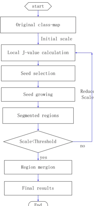
Figure 2. Flow-chart of the JSEG algorithm
B. Object Segmentation and Signal Decomposition Image segmentation is a key technology in the field of image processing and many algorithms have been proposed. In this paper, the JSEG algorithm is employed to implement segmentation which is a classical region-based image segmentation technique [7, 8].
JSEG consists of two main steps, color quantization and spatial segmentation. The purpose of the first step is to reduce the number of colors to lower the complexity of segmentation. Typically, 10-20 representative colors are retained and are used [9]. After color quantification, a class-map is acquired, which can be viewed as a special gray image. In the class-map, the pixel’s values are not real color values but the colors’ class labels. The spatial segmentation is not directly implemented on the class-map but on the so called J class-map. Fig. 2 shows the flow chart of JSEG.
object-based coding. Hence, the map is firstly pre-processed before embedded coding. Two pre-processing measures are taken: median filtering and re-labeling:
1) Median filtering: The aim is to eliminate noise and remove vey tiny regions that may occur. We use a 3 × 3 median filter.
2) Re-labeling: This step it to mark all the pixels within an object with the same label and each object is marked a unique label with regular values (e.g. 1, 2, …, M).
After segmentation, a binary labeling mask can be derived for each object
O
i. Assumef
( )
x
,
y
is the binarylabeling mask of
O
i and it can be defined as
⎩
⎨
⎧
∉
∈
=
i io
y
x
d
o
y
x
d
y
x
f
)
,
(
0
)
,
(
1
)
,
(
(1)where
d
( )
x
,
y
denotes image pixel.DWT can concentrate the energy of the original image to a few wavelet coefficients. In this paper, we use the 9/7 wavelet. After DWT, for each object we can acquire a low-frequency subset and several high-frequency subsets.
start
Initialize location information for each object
Location bit-plane coding
Effective bit-plane coding
Highest effective bit-plane? Clean-up pass Finish all planes? End yes no Sign bit-plane coding
yes
no
Significance pass
Refinement pass
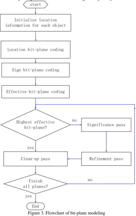
Figure 3. Flowchart of bit-plane modeling
C. Bit-plane Modeling and Entropy Coding
To perform object-based embedded coding, the binary mask for each object is encoded as an additional bit-plane. We scan and code the bit planes from the highest to the lowest and generate a context
Cx
for each bit D(0or1).The process of bit-plane coding employs three coding passes, significance pass P1, refinement pass P2, and cleanup pass P3. There are four coding methods to scan and code the coefficient bits for these three coding passes, zero coding (ZC), significance coding (SC), magnitude refinement coding (MRC), and run length coding (RLC) [10]. The main steps of the bit-plane modeling are shown in Fig. 3.
After coefficient-bit modeling, MQ arithmetic coding is performed. Its task is to convert the binary bits D and context data
Cx
into a tight bit stream. Each pass of a bit-plane in a sub-band of an object is encoded to produce an elementary stream. All the elementary streams of all objects can be further reassembled based on optimal rate-distortion principle to form embedded stream.D. Rate Control
The main task of rate control is to truncate and reassemble bit streams to minimize the total distortion under given bit-rate constraints. In this paper, for our proposed object-based coding scheme, it is equivalent to find an optimal truncation point
n
i for each objectO
i to minimize the distortion at each sub-band, which can be formulated as follows by employing Lagrange principle:
(
i)
i i i n o i n o
D
R
+
λ
∑
(2)where
λ
is the Lagrange multiplier, i in o
R
denotes thenumber of bits generated by
O
i at truncation pointi
n
, ii
n o
D
denote the corresponding distortion incurred. The proposed rate control algorithm mainly consists of three main steps: Target bit-allocation, distortion estimation, rate-distortion optimized truncation. The details of the proposed algorithm are introduced as follows:1) Target bit allocation.
To begin with rate-control, each sub-band after DWT is allocated a target bit rate. Let
R
target denote theoverall target bit-rate for the whole image. Then the target bit rate for the jth sub-band can be given:
[ ]
t et jallot
W
j
R
R
=
×
arg (3)Where
R
allotj denotes the target bit-rate for the jthsub-band,
w
[
j
]
is its corresponding weighting coefficient, which is defined to signify the importance of the sub-band and can be calculated by
∑
∑
∈ ∈=
I j S n m n m S n m n mX
X
j
W
) , ( , ) , ( ,]
Where
X
m,n denotes the wavelet coefficient,S
I andj
S
denote the whole image and thej
th sub-band respectively.2) Distortion estimation
When finishing encoding a pass, the increased number of bits is available. And for implementing rate-distortion optimized truncation, its corresponding distortion should also be calculated. For simplicity, the distortion is often estimated.
Let j ip
n o
R
Δ
denote the number of bits generated bypass
n
jat thep
th plane of objectO
i, and j ipn o
D
Δ
denotethe corresponding distortion difference. Let
f
(
h
,
k
)
i
o
denote the magnitude of coefficient
(
h
,
k
)
belonging to objectO
i. Then thej ip
n o
D
Δ
of significance propagation pass and clean up pass can be calculated as follows:∑
∈=
Δ
j i j ip n k h p o j p no
w
n
d
h
k
D
) , ( 2))
,
(
((
)
(
2
)
)
5
.
1
)
,
(
(
−
2−
d
opih
k
⎣
2
(
,
)
⎦
2
)
,
(
2
)
,
(
h
k
f
h
k
1f
h
k
d
i i i o p o p p o − − −−
⋅
=
(5)where
⎣ ⎦
x
is the floor function which indicates thelargest integer not exceeding
x
. While for the magnituderefinement pass, the j ip
n o
D
Δ
is calculated by∑
∈−
=
Δ
j i j ip n k h p o j p no
w
n
d
h
k
D
) , ( 2)
1
)
,
(
((
)
(
2
)
)
)
,
(
(
d
oph
k
K
2i
−
−
(6)If the current bit is 0,
K
=
0
.
5
, otherwiseK
=
1
.
5
. 3) Truncation point selectionFor each object, after finish coding all the passes of an object in a sub-band, the optimal truncation point
n
iwhich minimizes i
i i i n o n o
D
R
+
λ
, need to be found. It isdifficult and complex to directly look for the optimal truncation point. In practical applications, this task can be separated into two major steps. The first one is to determine candidate truncation points from all the possible ones. Then secondly, we can find the optimal truncation point from the set of candidate ones. The steps for determining candidate truncation points are as follows: (a) Set
N
i=
{ }
n
i ,that is, the set of all possibletruncation points.
(b) Let
p
=
0
and calculateS
i0=
Δ
D
i0/
Δ
R
i0.(c) Calculate
S
ip+1=
Δ
D
ip+1/
Δ
R
ip+1. (d) If ipp
i
S
S
+1>
, go to (e), else go to (f).(e) Delete
n
p fromN
i ,p i p
i p
i
D
D
D
=
Δ
+
Δ
Δ
+1 +1, p i p i p
i
R
R
R
=
Δ
+
Δ
Δ
+1 +1, and recalculate
S
ip+1. (f) Letp
=
p
+
1
and return (c)Once the set of candidate truncation points is determined, the next task is to find the optimal
n
i for each object, which is equivalent to find the optimal rate-distortion slopeλ
−opt1 .The steps are briefly introduced asfollows:
(a)Look for the maximum and the minimum rate distortion slopes in the subband and determine the range of
λ
−1 :[
min_
S
,
max_
S
]
.(b) Establish a new function:
( ) ( )
jallot
R
R
F
λ
−1=
λ
−1−
(7)Now the problem is to find an approximate root of the function. We can find an optimal
λ
−opt1 based on bisectionmethod.
λ
−opt1 is optimal in the sense that( )
jallot opt
R
R
λ
−1≤
, and there is no otherλ
that can meet( ) ( )
jallot
opt
R
R
R
λ
−1≤
λ
−1≤
.In general, the smaller
λ
−1 is, the larger the bit-rate generated by the optimized intercept point will be. Hence the functionF
( ) ( )
λ
−1=
R
λ
−1−
R
allotj is a monotonically increasing function ofμ
−1.(c) All the coding passes whose rate distortion slopes are no smaller than
λ
−opt1 are kept and others are discarded.After finish encoding one sub-band, update the target bit rate
R
target=
R
target−
R
tjarget and go on with thenext till all are finished.
III.EXPERIMENTAL RESULTS
In order to evaluate the performance of the proposed algorithm, experiments are conducted. The test images are randomly searched from Google image data set. We mainly investigate the effectiveness of the scheme, the rate-control precision and the quality of decoded images and objects. One metric, rate-control deviation
δ
d , is defined to reflect the rate-control precision. The smallerd
δ
is, the better the rate-control precision will be. The metric is defined as:et t et t a
d
=
|
R
−
R
arg|
R
argδ
(8)where
R
targetandR
a are the target and actual bit ratesrespectively.
rates), Table 1-Table 3 give the corresponding PSNRs and rate deviations, Fig. 7-Fig. 9 are reconstructed versions of several objects at different compression ratios
and Table 4 shows the corresponding PSNRs. From the experimental results, we can see that the
overall object-based scheme is effective. From Fig. 4-Fig. 6 and Table 1-Table 3, one can see that the scheme can encode and decode an image correctly and effectively according to the given bit rates. The rate-control algorithm is efficient and rate-control precision is good. From Fig. 7-Fig. 9 and Table 4, one can tell that the objects in an image can be encoded and decoded independently and progressively depending on the given bit-rate.
Compared with previous block-based techniques, our scheme has several advantages. Firstly, because an original image is segmented into objects and they are
taken as basic coding units and are encoded independently, our scheme makes the content-based random access and the content-based scalability available. Secondly, the blocking artifacts can be reduced, especially at low bit-rates. In block-based scheme, each block is encoded independently and the correlations among blocks are removed, the border between two blocks may become clear leading to the known block artifact when the numbers of compressed bits of them differ greatly. Finally, the characteristics of human visual system can be incorporated into distortion assessment and estimation when implementing bit truncation and reassemble. It can further optimize the rate-distortion performance. As a whole, the proposed scheme is more flexible and can enhance the overall subjective image quality.
(a) (b) (c) (d) (e)
Figure 4. Reconstructed images of Satellite image at different compression ratios, where (a) is original image, (b),(c),(d),(e)are reconstructed images at compression ratio 2,4,8 and 16, respectively.
(a) (b) (c) (d) (e)
Figure 5. Reconstructed images of Flower image at different compression ratios, where (a) is original image, (b),(c),(d),(e)are reconstructed images at compression ratio 2,4,8 and 16, respectively.
(a) (b) (c) (d) (e)
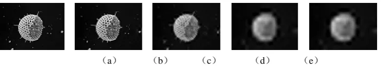
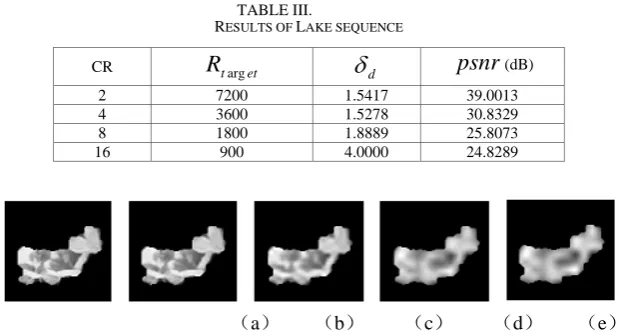
Figure 6. Reconstructed images of Lake image at different compression ratios, where (a) is original image, (b),(c),(d),(e)are reconstructed images at compression ratio 2,4,8 and 16, respectively.
TABLE I.
RESULTS OF SATELLITE SEQUENCE
CR
R
targetδ
dpsnr
(dB)2 6528 5.4688 37.7114
4 3264 1.4706 27.7808
8 1632 3.3088 23.2437
16 816 4.2892 22.0503
TABLE II.
RESULTS OF FLOWER SEQUENCE
CR
R
targetδ
dpsnr
(dB)2 8320 1.1899 33.5455
4 4160 2.5481 25.5519
8 2080 1.6827 23.5410
TABLE III.
RESULTS OF LAKE SEQUENCE
CR
R
targetδ
dpsnr
(dB)2 7200 1.5417 39.0013
4 3600 1.5278 30.8329
8 1800 1.8889 25.8073
16 900 4.0000 24.8289
(a) (b) (c) (d) (e)
Figure 7. Reconstructed versions of object 1 of Flower image at different compression ratios, , where (a) is original image, (b),(c),(d),(e)are reconstructed images at compression ratio 2,4,8 and 16, respectively.
(a) (b) (c) (d) (e)
Figure 8. Reconstructed versions of object 1 of Satellite image at different compression ratios, , where (a) is original image, (b),(c),(d),(e)are reconstructed images at compression ratio 2,4,8 and 16, respectively.
(a) (b) (c) (d) (e)
Figure 9. Reconstructed versions of object 1 of Lake image at different compression ratios, , where (a) is original image, (b),(c),(d),(e)are reconstructed images at compression ratio 2,4,8 and 16, respectively.
TABLE IV.
PSNRS OF RECONSTRUCTED OBJECTS AT DIFFERENT COMPRESSION RATIOS
CR Objects
Object1of Satellite Object1 of Lake Object1 of Flower
2 44.3429 44.2168 38.4299
4 28.0185 37.9931 30.5999
8 22.5058 29.3615 26.3518
16 21.8989 27.8995 25.6703
IV.CONCLUSION
In this paper, the issue of object-based embedded image coding is addressed and based on conventional block-based EBCOT algorithm, an object-based embedded coding with optimized truncation algorithm is proposed. The proposed new algorithm takes object as the basic coding unit and each object in an image can be encoded and decoded independently with different strategy according to its visual interest. Every pass of an object is compressed into an elementary stream. All the elementary streams of all objects can be further reassembled based on optimal rate-distortion principle to form a final embedded stream. As a whole, the improved
algorithm is more flexible and can enhance the overall subjective image quality.
ACKNOWLEDGMENT
This work was supported in part by the National Natural Science Foundation of China (No.60902066); the Natural Science Foundation of Zhejiang Province (No.Y107740); the Science Research Foundation of Education Department of Zhejiang Province (No: Y201016875, Y201018538 ).
REFERENCES
[1] J. M. Shapiro, “Smart compression using the embedded
Proceedings of the 27th. Annual Asilomar Conference on Signals, Systems and Computers, vol. 1, Pacific Grove, CA, Nov. 1993, pp. 486-490.
[2] A. Said, W. A. Pearlman, “A new fast and efficient image codec based on partitioning in hierarchical trees,” IEEE Tran. on Circuits and System for Video Technology, vol. 6, pp. 243-249, Jun. 1996.
[3] ISO/IEC JTC1/SC29/WG1 N505, “Call for Contributions
for JPEG2000 (JTC 1.29.14, 15444),” Image Coding System, Mar. 1997.
[4] D. Taubman, “High performance scalable image
compression with EBCOT,” IEEE Transactions on Image Processing, vol. 9, pp. 1158-1170, Jul. 2000.
[5] W. Pennebaker, J. Mitchell, JPEG: Still image data
compression standard, New York: Van Nostrand Reinhold, NY, 1992.
[6] Y. J. Li; M. Bayoumi, “A Three-Level Parallel High-Speed Low-Power Architecture for EBCOT of JPEG 2000,”
IEEE Transactions on Circuits and Systems for Video Technology, Volume: 16, pp.1153 – 1163, Sept. 2006 [7] H. D. Cheng, Y. Sun, “A Hierarchical Approach to Color
Image Segmentation Using Homogeneity,” IEEE Trans on Image Processing, vol. 19, pp. 2071-2082, Dec. 2000.
[8] Y. N. Deng, B. S. Manjunath, “Unsupervised
Segmentation of Color-Texture Regions in Images and
Video,” IEEE Transactions On Pattern Analysis and
Machine Intelligence, vol. 23, pp.800-810, Aug. 2001 [9] Y. N. Deng, C. Kermey, M. Moore, “Peer Group Filtering
and Perceptual Color Image Quantization,” IEEE
International Symposium on Circuits and System, vol.4, Orlando, FL,Jun. 1999, pp. 21-24.
[10]Y. Z. Zhang, C. Xu, W. T. Wang, L. B. Chen, “Performance Analysis and Architecture Design for
Parallel EBCOT Encoder of JPEG2000,” IEEE