Performance Analysis of MIMO-OFDM based
IEEE 802.11n using Different Modulation
Techniques
Sandeep Kaur Joy Karan Singh
M. Tech Research Scholar Assistant Professor
Department of Electronics & Communication Engineering Department of Electronics & Communication Engineering CT Institute of Technology & ResearchJalandhar, Punjab CT Institute of Technology & ResearchJalandhar, Punjab
Anurag Sharma
Assistant Professor
Department of Electronics & Communication Engineering CT Institute of Technology & ResearchJalandhar, Punjab
Abstract
OFDM is a most popular method that used for high data rate in wireless communication. In OFDM combined with antenna arrays at transmitter and receiver side is called MIMO-OFDM and other word MIMO-OFDM system is a consist or combination of the MIMO technique and OFDM technique that use due to increase the diversity gain, time-variant, frequency-selective channels, enhance the system capacity and improve the link reliability high data rate transmission that used for future broadband wireless communication and that are mostly use for avoid Inter-Symbol Interference (ISI) and Inter-Carrier-Interference (ICI). This paper explores physical layer research with IEEE 802.11n standard challenges with different modulation techniques and finds the BER (bit error rate) modulation techniques (BPSK, QPSK, and 712-qam). IEEE 802.11n is a communication standard that provides higher significant throughput and higher date rate.
Keywords: Binary Phase Shift Keying (BPSK), multiple-input- multiple-output (MIMO), orthogonal frequency division multiplexing (OFDM), Bit error rate (BER), Additive White Gaussian Noise (AWGN), QAM (Quadrature amplitude modulation)
_______________________________________________________________________________________________________
I. INTRODUCTION
II. MIMO-OFDM BASED IEEE 802.11N
MIMO System Model:
First, IEEE 802.11n has been applied in a system with many transmitter antenna and receiver antenna and combined with multicarrier modulation techniques known as MIMO-OFDM and IEEE 802.11n is an increase throughput that my aimed to improve a performance in physical layer so IEEE 802.11n standard used that are development of IEEE 802.11(a /g) standards[5]. IEEE 802.11n is a WLAN IEEE 802.11n is capable of support the user and through provide a good quality video streaming for multiple users (For example: WLAN network that used for video conference) and OFDM is provide a high throughput (gigabyte) as well as to stable or good the quality of service(QoS) network better than other WLAN standards[5]. IEEE 802.11n WLAN standard used in then MIMO-OFDM system is able to provide higher data rate and then the original data rate which can reach from 54 Mb/s to 600 Mb/s[6]. This is the first wireless LAN standard based on MIMO-OFDM, techniques to give a significant performance increase in range and rate relative to conventional wireless LAN. When performances of the OFDM system net user throughputs over 100 Mbps are achievable, in which when to applying an IEEE 802.11n standard four times larger throughputs is achieved and these achieved throughput are maximum as compared achievable throughput using IEEE 802.11a/g standard [7]. For the same throughput, MIMO-OFDM achieves a range that is three times larger than as compared to non-MIMO systems. In this significant more improve performance MIMO-OFDM with the help of increased the data rate and with the help of IEEE 802.11n standard. The MIMO-OFDM not only used for wireless LAN but also used for home entertainment networks and 4G networks or system. MIMO is a wireless technology that is used for transmissions over wireless links but the signal is taken with the help of multiple antennas equipped at both the transmitter as well as receiver. MIMO systems may be consist of a number is different ways and these are obtaining a diversity gain to combat signal fading and good capacity or gain that mean improve the performance of the system.
Fig. 1: MIMO antennas system model [8]
The OFDM is an achieving higher data rate and providing a more reliable reception performance as compared to single-antenna system for wireless communications that is not more reliable reception. Now just taken as an example of MIMO applications, the IEEE 802.11n standard is a still discussed, but in which one prototype can offer up to 250 Mbps and that is more than five times the speed of the existing IEEE 802.11g. In wideband channels, OFDM has used MIMO techniques and that used is most important and benefit like ISI reduction and capacity improvement.
In Fig:1. Output user system is a y = Hs + η. Where S= [S1 S2…SM]t is the transmitted data vector, y = [y1 y2………yM]t is
the received data vector, and η =[ η1 η2……. ηM]t is anadditive white Gaussian noise and assumes that in MIMO system MT is
Modulation Techniques:
In this paper discussed a basic and popular digital modulation scheme like:- 1) Binary Phase Shift Keying (BPSK)
2) QAM(Quadrature amplitude modulation) 3) QPSK (Quadrature phase shift key)
BPSK is a phase shift keying (PSK) and a digital modulation scheme in BPSK phase of the carrier is changed and modulated according to the modulating waveform which is called digitally modulated the signal. In BPSK the transmitted signal is a sine wave of fixed amplitude. It has one fixed phase when the data is at one level and the data is at the other level in BPSK, the phase is different by 180 degrees. In QPSK is also known as quadric-phase PSK, 4-PSK, or 4-QAM With four phases, QPSK is a encode two bits per symbol, when QPSK applied a Gray coding to Minimize the bit error rate (BER) [10]. QPSK can be used for or either to double the data rate compared with a BPSK system and also maintaining the same bandwidth of the signal or to maintain the data rate of BPSK but halving the bandwidth needed. QAM is analog and digital modulation scheme. It conveys two analog message signals or two digital bit streams, by changing the amplitudes of two carrier waves with the help when applied an amplitude-shift keying (ASK) in digital modulation scheme or as well as applied amplitude modulation (AM) in analog modulation scheme. The two carrier waves are usually sinusoids and these are out of phase with each other by 90° then is called quadrature carriers or quadrature components [11].The modulated waves are summed, and the resulting waveform is a combination of both phase shift keying (PSK) and amplitude-shift keying (ASK), in the case of the analog or phase modulation (PM) and amplitude modulation. In the digital QAM has a finite number but in which least two phases and at least two amplitudes are used.
Additive White Gaussian Noise:
AWGN channel is a channel when signal pass through channel and it adds a white Gaussian noise and in AWGN channel amplitude frequency response is flat and in which unlimited or infinite bandwidth and phase of frequency response is linear for all frequencies that mean modulated signals pass through it without any amplitude loss (amplitude distortion) and without phase distortion of frequency components and so fading does not exist or occur. The only distortion is introduced by the AWGN. The received signal is simplified by:-
r(t) = x(t)+n(t)
In this equation n(t) is a the additive white Gaussian noise. The whiteness of n(t) implies that it is a random process and a flat power spectral density (PSD) for all frequencies[12].
III. RESULTS AND DISCUSSIONS
In BPSK and QPSK:
Table – 1
Simulation parameter Simulation parameter value
No. of transmitted bit 1280
Cyclic prefix 256
Channel AWGN
Modulation techniques BPSK, QPSK
Band Width 20MHz-40MHz
MC (machine cycles) 50
nFFT 1024
No. of transmitter and receiver nTx = nRx = 2
The Figure 2 & 3 presents a BPSK simulation results that show in table No. 1 in which figure No. 2 show the comparison between BER VS SNR at different time and the figure No.3 show transmitted data pass through after modulator at the transmitter side and received data after demodulation at receiver side.
Fig. 2: shows performance analysis of BPSK.
Fig. 3: Shows the Transmitted and received messages in BPSK
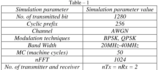
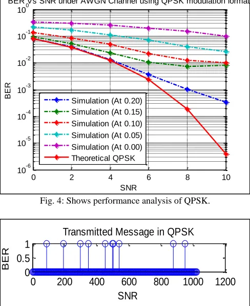
The Figure 4 & 5 presents a QPSK simulation results that show in table No. 1 in which figure No. 4 show the comparison between BER VS SNR at different time and the figure No.5 show transmitted data pass through after modulator at the transmitter side and received data after demodulation at receiver side
0 2 4 6 8 10
10-6
10-5
10-4
10-3
10-2
10-1
100
BER Vs SNR under AWGN Channel using BPSK modulation format
SNR
BER
Simulation (At 0.20) Simulation (At 0.15) Simulation (At 0.10) Simulation (At 0.05) Simulation (At 0.00) Theoretical BPSK
0 200 400 600 800 1000 1200
0 0.5 1
Transmitted Message in BPSK
SNR
BER
0 200 400 600 800 1000 1200
0 0.5 1
Received Message in BPSK
SNR
Fig. 4: Shows performance analysis of QPSK.
Fig. 5: Shows the Transmitted and received messages in QPSK
In 512-QAM:
Table – 2
Simulation parameter Simulation parameter value No. of transmitted bit 640
Cyclic prefix 128
Channel AWGN
Modulation technique 512-QAM
Band Width 20MHz-40MHz
MC (machine cycles) 50
M 9
No. of transmitter and receiver nTx = nRx = 2
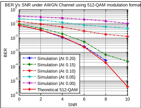
The Figure 6 & 7 presents a QAM-512 simulation results that show in table No. 2 in which figure No. 2 show the comparison between BER VS SNR at different time and the figure No.7 show transmitted data pass through after modulator at the transmitter side and received data after demodulation at receiver side
0 2 4 6 8 10
10-6
10-5
10-4
10-3
10-2
10-1
100
BER Vs SNR under AWGN Channel using QPSK modulation format
SNR
BER
Simulation (At 0.20) Simulation (At 0.15) Simulation (At 0.10) Simulation (At 0.05) Simulation (At 0.00) Theoretical QPSK
0 200 400 600 800 1000 1200
0 0.5 1
Transmitted Message in QPSK
SNR
BER
0 200 400 600 800 1000 1200
0 0.5 1
Received Message in QPSK
SNR
Fig. 6: Shows performance analysis of 512-QAM.
Fig. 7: Shows the Transmitted and received messages in 512-QAM
Table – 3
Comparison Table of Snr Vs Ber Different Modulation Techniques of AWGN Channel Applied IEEE 802.11n TIME(sec) SNR BER BPSK BER QPSK BER 512-QAM
0.00 0 0.0808 0.0792 0.0772
2 0.0391 0.0401 0.0362 4 0.0121 0.0134 0.0121 6 0.0024 0.0034 0.0029 8 2.3438e04 8.9844e04 1.9663e-04
10 0 2.9297e04 0
0.05 0 0.0936 0.0969 0.0968
2 0.0482 0.0516 0.0518 4 0.0210 0.0239 0.0211 6 0.0079 0.0101 0.0063 8 0.0032 0.0069 0.0013 10 0.0023 0.0075 5.0562e04
0.10 0 0.1409 0.1420 0.1553
2 0.0894 0.0878 0.1046 4 0.0511 0.0467 0.0624 6 0.0236 0.0237 0.0335 8 0.0135 0.0119 0.0220 10 0.0103 0.0096 0.0194
0.15 0 0.2201 0.2205 0.2274
2 0.1661 0.1642 0.1799 4 0.1189 0.1134 0.1397 6 0.0754 0.0689 0.0986 8 0.0437 0.0395 0.0618
0 2 4 6 8 10
10-6
10-5
10-4
10-3
10-2
10-1
100
BER Vs SNR under AWGN Channel using 512-QAM modulation format
SNR
BER
Simulation (At 0.20) Simulation (At 0.15) Simulation (At 0.10) Simulation (At 0.05) Simulation (At 0.00)
Theoretical 512-QAM
0 200 400 600
0 0.5 1
Transmitted Message in 512-QAM
SNR
BER
0 200 400 600
0 0.5 1
Received Message in 512-QAM
SNR
10 0.0279 0.0248 0.0499
0.20 0 0.3404 0.3399 0.3419
2 0.3029 0.3007 0.2997 4 0.2577 0.2584 0.2560 6 0.2045 0.2054 0.2044 8 0.1527 0.1526 0.1559 10 01005 0.1025 0.1115
IV. CONCLUSION
In this paper, we have evaluated the performance of MIMO-OFDM with the help of MATLAB tool. The main aim of the paper is to implement of different modulation techniques using MIMO-OFDM IEEE 802.11n and show the comparison analysis BER Vs SNR using AWGN channel. The Additive White Gaussian Noise (AWGN) corrupted the transmitted signal and this resulted in a different received 712-QAM, QPSK, and BPSK signal than the original signal show. The SNR for each modulation takes into account the number of bits error rate in each symbol at a different time (0.00sec, 0.05sec, 0.10sec, 0.15sec, 0.20sec) with the help of counter (machine cycle) and all result shows in comparisons table or figures. In which, SNR is increased then BER has decreased it mean SNR inversely proportional to BER. BPSK and 512-QAM both modulation techniques almost similar performed as compared to QPSK. All over simulation results show the BPSK modulation technique is better performed as compared to 512-QAM, QPSK, when MIMO-OFDM system include a IEEE 802.11n standard.
REFERENCES
[1] A. Oborina, M. Moisio, and V. Koivunen, “Performance of Mobile MIMO OFDM Systems with Application to UTRAN LTE Downlink," in IEEE Transactions on Wireless Communications, Vol. 11, pp.70-79, 2012.
[2] X. Zhang, “Modeling & Performance Analysis of QAM-based COFDM System” University of Toledo, Vol.3, 2011.
[3] H. Ajra, Md. Zahid Hasan, and M. S Islam, “BER Analysis of Various Channel Equalization Schemes of a QO-STBC Encoded OFDM based MIMO CDMA System”, “International Journal Computer Network and Information Security (IJCNIS), Vol.3, pp.30-36, 2014.
[4] G.G. Raleigh and J.M. Cioffi, “Spatio-Temporal Coding for Wireless Communications”, Proc.Global Telecommunications Conf., pp. 1809–1814,1996. [5] G.G. Raleigh and V.K. Jones, “Multivariate Modulation and Coding forWireless Communication”, IEEE Journal on Sel. Areas in Comm., Vol. 17, pp.
851–866, 1999.
[6] R. van Nee, A. van Zelst, and G. Awater, “Maximum Likelihood Decoding in a Space Division Multiplexing System”, IEEE conf., Vol.1,2000.
[7] A. S. Kushwah, “Performance Analysis of 2*4 MIMO-MC-CDMA in Rayleigh Fading Channel ZF-decoder,” International Journal of Engineering Trends and Technology (IJETT), Vol. 8, pp. 1- 4, 2014
[8] N. C. Giri, S. M. Ali, and R. Das, “ BER Analysis and Performance of MIMO-OFDM System using BPSK Modulation Scheme for Next Generation Communication Systems” IJETT, Vol.5, 2014
[9] M. A. Faisal, M. Hossain and S. E. Ulaah, “Perfomance Evaluation of a Antenna MC-CDMA System on Color Image Transmission under Implementation of Various Signal Detection Techniques,” International Journal of Advanced Science and Technology (IJAST), Vol. 41, pp. 71-82, 2012.
[10] R. T. Becker, “Precoding and Spatially Multiplexed MIMO in 3 GPP Long – Term Evolution, High Frequency Electronics”, IJETT, pp. 18 – 26, 2009, [11] D. Gesbert, M. Shafi, P. J. Smith, A. Nagui, and D. Shan Shiu, “From Theory to Practice: An Overview of MIMO," in IEEE Journal of Selected Topics in
Communications, vol. 21, 2003.
![Fig. 1: MIMO antennas system model [8]](https://thumb-us.123doks.com/thumbv2/123dok_us/7813221.1663321/2.612.175.436.305.529/fig-mimo-antennas-system-model.webp)