ISSN (e): 2250-3021, ISSN (p): 2278-8719
Vol. 09, Issue 7 (July. 2019), ||S (I) || PP 34-39
Implementation of Different modulation techniques for Eleven
Level Cascaded H-Bridge Inverter with Reduced Switch Count
Nishant Thakkar
1, Rakeshwri Agrawal
2, Deepak Agrawal
31Research scholar, Department of Electrical and Electronics Engineering, Trinity Institute of Technology &
Research, Bhopal, India
2,3Assistant Professor at Department of Electrical and Electronics Engineering, Trinity Institute of Technology
& Research, Bhopal, India
Abstract: In this paper a topology of Cascaded H-Bridge multi level inverter is proposed with reduced number of switches. The proposed topology has been implemented using four different modulation techniques. Also the performance analysisisdone to evaluate THD of the system under various load condition. The proposed topology is economical since to generate eleven level it require sonly eight switches and three isolated DC sources. More over the THD of the output voltage is also very low.
--- --- Date of Submission: 03-07-2019 Date of acceptance: 18-07-2019 --- ---
I.
INTRODUCTION
Power Electronics Devices (PED), especially DC to AC inverter are now-a-days widely used in industries because of numerous advantage they provide such as less energy consumption, better efficiency, good quality, less maintenance requirement etc.
In case of medium voltage grid, it is tough to directly connect one power semiconductor switch. And therefore a Multilevel Inverter (MLI) structure has been invented for high power and medium voltage applications for example, mills, pumps, laminators, blower, conveyers, fans, compressors etc. MLI also allow using low power application in renewable sources like wind photovoltaic and fuel cell, they also help in attaining high power rating that is too in a very cost effective way.
Initially and most commonly MLI application has been in traction, both locomotive and track side static converter. And recently they are used in VAR compensation and stability enhance emend, high voltage dc transmission, high voltage motor drive and also in medium voltage induction motor variable speed drive. In modern industrial application of multilevel inverter focuses on medium voltage motor drive, utility interface for renewable energy system, Flexible AC transmission system, and traction drive systems.
Since MLIs are used in such a wide areas and therefore they should be able to manage high voltage and large power. And that is why, two level high voltage and large power inverters are designed with series connection of switching power devices like gate turn off thyristors (GTO’s), integrated gate commutated transistors (IGCTs), and integrated bipolar transistor (IGBTs) because when they are connected in series high voltage can be achieved. On the other hand series combination has its own problems like non equal distribution of applied voltage across the devices that can cause the applied voltage of each device higher than blocking voltage of individual device at the time of transient and steady state switching operation. In order to effectively solve the above described problem, many different topologies of MLI have been invented and utilized. As the name suggest there are multiple level of output voltage retrieved by many DC voltage sources. Also the quality of the output voltage is enhanced because of the increased voltage levels, so the cost and quality of the filter can be reduced.
make a MLI. The voltage or current rating of the MLI becomes a multiple of all the individual switches, and therefore the power rating of the converter can cross the limit imposed by the individual switching devices.
To obtain higher power, the basic concept of a MLI is to use semiconductor switches in series with many lower level voltage dc sources to do power conversion by synthesizing a stair like voltage waveform. Batteries, capacitors and renewable voltage sources can be used for multiple dc voltage sources. To achieve high voltage at the output the commutation of the power switches plays an important role. Power semiconductor’s devices rated voltage depends upon the rating of dc voltage sources they are connected to.
II.
CASCADED H BRIDGE MLI
H Bridge is now a day used in high power AC supplies and adjustable speed drive application. A CHB-MLI is made by the series combination of H bridge (single phase full bridge) inverter unit in each of its three phases. Every H Bridge unit consists of its own dc sources, which will be a battery unit for an induction motor and fuel cell or solar cell. Every SDC (separate D.C. source) is concerned with the single phase full bridge inverter. The AC terminal voltages are connected in series. With the help of different combination of the four switches it is Vdc, -Vdc and zero. The AC output of the full bridge converters which are in same phase are connected in series and are able to obtain the voltage waveform which is the sum of the converters output. Also the number of output voltages is in a total different way from those of the DC and FC type. Here in the proposed topology the number of output voltage levels is obtained by m = 2N +1, where N is the number of DC sources. For example, in case of a seven level CHB-MLI the total number of DC sources are three and the total number of full bridge converter is also three. If the conducting angle at different converter level is controlled then minimum harmonic distortion can be obtained. A quasi square waveform is produced by each H bridge unit by phase shifting the positive and negative phase legs switching timings. Each of the switching device conducts for 1800 , independent of the pulse width of the quasi square wave. The entire switching devices current stress equal by this switching method. The power will flow from the batteries through the cascaded inverters to the motor in the motoring mode. The cascaded converter acts as rectifiers and power will flow from charger to the batteries in the case of charging mode. If regenerative braking is used then the cascaded converter is can also use as a rectifier the help in recovering the kinetic energy. The cascaded inverters are also used in parallel HEV configuration. With the help of this new converter the problem of extra clamping diodes or voltage balancing capacitors can be overcome. The combination pair of the 180° conducting method and pattern -swapping scheme make the voltage and current stresses of the cascade inverter’s the equal and battery voltage balanced. Identical H -bridge inverter units can be used, therefore improving modularity and Manufacturability and to a high extent reducing production costs. Battery -fed cascade inverter prototype driving an induction motor at speed of 50% and 80% that is rated speed both the voltage and current are almost sinusoidal. EMI and the common mode voltage are very less than what would be obtained from a PWM inverter because of the excessively low dv/dt and sinusoidal voltage output.
The main advantages of utilizing the cascade inverter in an induction motor are:
1) This makes an induction motor more accessible/safer and also open wiring is possible for most of an induction motor power system.
2) Earlier 230 V or 460 V motors can be utilized, thus higher efficiency is expected as compared to low voltage motors.
3) There is no EMI problem or common -mode voltage/current problem occurs. 4) Low voltage switching devices can also be used.
No charge unbalance problem appears in both charge mode and drive mode. CHB-MLI are very useful in case of an induction motor (IM) that has many number of separate dc sources (batteries) each for the individual H bridges, these inverters are not an option in case of series hybrid IMs because we know that CHB-MLI are not easy to be connected back -to-back. In case of series-configured IMs where an on-board combustion engine produces ac power with the help of an alternator or generator, a multilevel back -to-back diode clamped inverter drive can best interface with the source of ac power and yet still it is easily meet the high power and/or high voltage requirements of the IM.
IMs usually have an ac voltage source produced from an alternator or combustion engine generator. A rectifier will convert this AC voltage into DC voltage for theelectric energy storagedevices onboard – batteries or capacitors. An inverter will help in converting the DC voltage into a variable voltage and variable frequency ac in order to drive the main IM.
III.
PROPOSED CHB-MLI TOPOLOGY
Vdc
S1
S2
S3
S4
2Vdc
S1'
S2'
S3'
S4'
2Vdc
R load
Figure-1 Proposed configuration of CHB-MLI
IV. SIMULATION AND RESULT DISCUSSION
Four different PWM techniques are used and they are In-phase disposition, Alternate phase Opposition disposition, Carrier wave and variable frequency. Triangular wave generators are used to produce these methods Simulation results of a three phase 11level inverter are shown using four different PWM techniques and also their Total Harmonic reduction is shown. A comparison between these methods is also discussed. The simulation is performed using MATLAB. The proposed topology is test for R and RL load and THD of the output voltage waveforms is analyzed.
Table-1 Component and rating used in the proposed topology.
Components Ratings
R load 124 ohms
RL load 115 ohms and 182mH
switching frequency 10khz
LC filter 1e-3 H and 1e-6 F
frequency=50 Hz 0.96mH
Simulation results for In-phase Disposition (IPD)
Figure 2 Output voltage of 11 level CHB-MLI for R load using IPD PWM
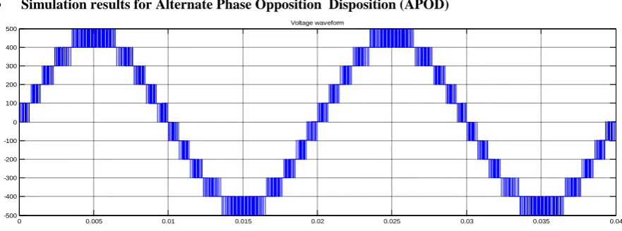
Simulation results for Alternate Phase Opposition Disposition (APOD)
Figure 3 Output voltage of 11 level CHB-MLI for R load using APOD PWM
Simulation results for Carrier overlap (CO)
Figure 4 Output voltage of 11 level CHB-MLI for R load using CO PWM
0 0.005 0.01 0.015 0.02 0.025 0.03 0.035 0.04
-400 -300 -200 -100 0 100 200 300
400 Voltage waveform
0 0.005 0.01 0.015 0.02 0.025 0.03 0.035 0.04
-500 -400 -300 -200 -100 0 100 200 300 400
500 Voltage waveform
0 0.005 0.01 0.015 0.02 0.025 0.03 0.035 0.04
-500 -400 -300 -200 -100 0 100 200 300 400
• Simulation results for Variable Frequency (VF)
Figure 5 Output voltage of 11 level CHB-MLI for R load using VFPWM
The THD analysis of the output voltage waveform is carried out for both R load and RL load whose comparative analysis is presented in Table-2. To reduce the THD a filter component is also added with the converter circuit whose results are presented in Table 2. The comparative analysis of the various topologies for component requirement is also done which is presented in Table 3.
Table-2 comparison of THD for output voltage using different PWM techniques Level Shifted
PWM techniques
Without Filter With Filter R load RL load R load RL load
IPD 0.22 0.27 0.27 0.27
APOD 0.38 0.37 0.25 0.37
CO 1.80 1.81 1.80 1.81
VF 0.47 0.47 0.38 0.47
Table-3 comparison of the component requirement for various MLI topologies Inverter type
Parameter
Eleven level topology: m=11
FC NPC CHB Proposed CHB
Switching devices 20 20 20 8
Diodes 20 20 20 0
Clamping Diode 0 90 0 0
Capacitor balance 45 0 0 0
DC bus 10 10 5 3
V. CONCLUSION
Three Phase 11 level inverter topology with less number of switches is proposed and simulated. Various PWM methods are analyzed and compared.From simulation results and THD analysis it is found that In-phase level shift PWM method provides minimum 0.2% of THD in the output voltage. Therefore this will be the best PWM technique for inverter switching. The comparative analysis of the proposed topology with the generalized MLI topologies is done for the component requirement and it is found that the proposed topology required least no. of component for the same level of voltage as compared to other MLIs.
REFERENCES
[1]. Susheela, N., & Kumar, P. S. (2017). Performance Evaluation of Carrier Based PWM Techniques for Hybrid Multilevel Inverters with Reduced Number of Components. Energy Procedia, 117, 635-642. [2]. Satti, M. B., Hasan, A., & Ahmad, M. I. (2018). A New Multilevel Inverter Topology for Grid-Connected
Photovoltaic Systems. International Journal of Photoenergy, 2018.
[3]. Buticchi, G., Concari, C., Franceschini, G., Lorenzani, E., &Zanchetta, P. (2012, September). A nine-level grid-connected photovoltaic inverter based on cascaded full-bridge with flying capacitor. In 2012 IEEE Energy Conversion Congress and Exposition (ECCE) (pp. 1149-1156). IEEE.
0 0.005 0.01 0.015 0.02 0.025 0.03 0.035 0.04
-400 -300 -200 -100 0 100 200 300 400
International organization of Scientific Research
39 | P a g e
[4]. Kumar, V., Pandey, A. S., & Sinha, S. K. (2016, March). Grid integration and power quality issues ofwind and solar energy system: A review. In 2016 International Conference on Emerging Trends in Electrical Electronics & Sustainable Energy Systems (ICETEESES) (pp. 71-80). IEEE.
[5]. Nikhil Kumar, Suresh K Gawre, Deepak Verma, ―Modeling and Simulation of Solar Photovoltaic System and Interfacing with Neutral Point clamped Multilevel Inverter‖, International Conference in Electrical, Electronics and Computer Science (ICEECS-2014), Chennai, Tamil Nadu, 30 March.
[6]. Grandi, G., Rossi, C., Ostojic, D., &Casadei, D. (2009). A new multilevel conversion structure for grid-connected PV applications. IEEE Transactions on Industrial Electronics, 56(11), 4416-4426.
[7]. Ulsrud, K., Winther, T., Palit, D., Rohracher, H., &Sandgren, J. (2011). The Solar Transitions research on solar mini-grids in India: Learning from local cases of innovative socio-technical systems. Energy for Sustainable Development, 15(3), 293-303.
[8]. El Nozahy, M. S., &Salama, M. M. A. (2013). Technical impacts of grid-connected photovoltaic systems on electrical networks—A review. Journal of Renewable and Sustainable Energy, 5(3), 032702.
[9]. Libo, W., Zhengming, Z., &Jianzheng, L. (2007). A single-stage three-phase grid-connected photovoltaic system with modified MPPT method and reactive power compensation. IEEE Transactions on Energy Conversion, 22(4), 881-886.
[10]. Corzine, K. (2005). Operation and design of multilevel inverters. Developed for the office of naval research.
[11]. de Oliveira, F. M., da Silva, S. A. O., Durand, F. R., Sampaio, L. P., Bacon, V. D., &Campanhol, L. B. (2016). Grid-tied photovoltaic system based on PSO MPPT technique with active power line conditioning. IET Power Electronics, 9(6), 1180-1191.
[12]. Molina, M. G., dos Santos, E. C., &Pacas, M. (2010, November). Improved power conditioning system for grid integration of photovoltaic solar energy conversion systems. In 2010 IEEE/PES Transmission and Distribution Conference and Exposition: Latin America (T&D-LA) (pp. 163-170). IEEE.
[13]. Daher, S., Schmid, J., &Antunes, F. L. (2008). Multilevel inverter topologies for stand-alone PV systems. IEEE transactions on industrial electronics, 55(7), 2703-2712.
[14]. Mohan, N., &Undeland, T. M. (2007). Power electronics: converters, applications, and design. John wiley& sons.
[15]. Zambra, D. A., Rech, C., &Pinheiro, J. R. (2010). Comparison of neutral-point-clamped, symmetrical, and hybrid asymmetrical multilevel inverters. IEEE Transactions on Industrial Electronics, 57(7), 2297-2306.
[16]. Kouro, S., Malinowski, M., Gopakumar, K., Pou, J., Franquelo, L. G., Wu, B., & Leon, J. I. (2010). Recent advances and industrial applications of multilevel converters. IEEE Transactions on industrial electronics, 57(8), 2553-2580.
[17]. Tolbert, L. M., &Peng, F. Z. (1998, February). Multilevel converters for large electric drives. In APEC'98 Thirteenth Annual Applied Power Electronics Conference and Exposition (Vol. 2, pp. 530-536). IEEE. [18]. Vazquez, S., Leon, J. I., Carrasco, J. M., Franquelo, L. G., Galvan, E., Reyes, M., & Dominguez, E.
(2009). Analysis of the power balance in the cells of a multilevel cascaded H-bridge converter. IEEE Transactions on Industrial Electronics, 57(7), 2287-2296.
[19]. Tolbert, L. M., &Peng, F. Z. (2000). Multilevel converters as a utility interface for renewable energy systems. In 2000 Power Engineering Society Summer Meeting (Cat. No. 00CH37134) (Vol. 2, pp. 1271-1274). IEEE.
[20]. Brando, G., Dannier, A., Del Pizzo, A., & Rizzo, R. (2010, September). A high performance control technique of power electronic transformers in medium voltage grid-connected PV plants. In The XIX International Conference on Electrical Machines-ICEM 2010 (pp. 1-6). IEEE.
[21]. Peng, F. Z., McKeever, J. W., & Adams, D. J. (1997). Cascade multilevel inverters for utility applications (No. CONF-971160-1). Oak Ridge National Lab., TN (United States).
[22]. Noge, Y., &Itoh, J. I. (2012, June). Multi-level inverter with H-bridge clamp circuit for single-phase three-wire grid connection suitable for Super-junction/SiC MOSFET. In Proceedings of The 7th International Power Electronics and Motion Control Conference (Vol. 1, pp. 88-93). IEEE.
[23]. Rahim, N. A., &Selvaraj, J. (2009). Multistring five-level inverter with novel PWM control scheme for PV application. IEEE transactions on industrial electronics, 57(6), 2111-2123.
[24]. Tolbert, L. M., &Habetler, T. G. (1999). Novel multilevel inverter carrier-based PWM method. IEEE Transactions on industry applications, 35(5), 1098-1107.