http://www.sciencepublishinggroup.com/j/ajce doi: 10.11648/j.ajce.20170504.15
ISSN: 2330-8729 (Print); ISSN: 2330-8737 (Online)
Strain-Based Finite Element Analysis of Stiffened
Cylindrical Shell Roof
Attia Mousa
Department of Civil Engineering, University of Bahrain, Manama, Kingdom of Bahrain
Email address:
To cite this article:
Attia Mousa. Strain-Based Finite Element Analysis of Stiffened Cylindrical Shell Roof. American Journal of Civil Engineering. Vol. 5, No. 4, 2017, pp. 225-230. doi: 10.11648/j.ajce.20170504.15
Received: June 11, 2017; Accepted: June 28, 2017; Published: July 24, 2017
Abstract:
A new triangular cylindrical shell finite element is used to obtain an elastic linear analysis of a cylindrical shell roof. The element’s displacement fields are in terms of curvilinear coordinates, satisfy the exact requirement of rigid body modes of deformation and have five degrees of freedom at each of the three corner nodes. The efficiency of the developed element is first tested and then applied to analyze stiffened cylindrical shell roof. The results of the displacement and stress resultant along the stiffener are presented and a parametric study is carried out to find the effect of the varying geometry of the stiffener and the effect of axis rotation of the beam on the level of the internal forces.Keywords:
Finite Element, Strain-Based, Cylindrical Shell, Stiffened Cylindrical Shell1. Introduction
Stiffened cylindrical shells are widely used as structural components in engineering applications such as roofs, bridges, aircraft, ships and offshore structures. This is due to their superior performance under different load conditions. The most popular development of numerical solutions to such problems was the finite element method. Considerable attention has been given applying the finite element method of analysis to curved structures. The early work on the subject was presented by Grafton and Strome [1] who developed conical segments for the analysis of shells of revolution. Jones and Strome [3] modified the method and used curved meridional elements which were found to lead to considerably better results for the stresses. Further research led to the development of curved rectangular as well as cylindrical shell elements by Connor and Brebbia [3], Bogner et al [4], Cantin and Clough [5] and Sabir and Lock [6]. However, to model a shell of arbitrary or triangular shape by the finite element method, a triangular shell element is needed. Thus many authors have been occupied with the development of curved triangular shell elements and consequently many elements by Lindber et al [7] and Dawe [8] resulting in an improvement of the accuracy of the results. However, this improvement is achieved at the expense of more computer time as well as storage to assemble the overall structure matrix. Meanwhile, in
2. Theoretical Considerations
Displacements Fields for the New Triangular Cylindrical Finite Element
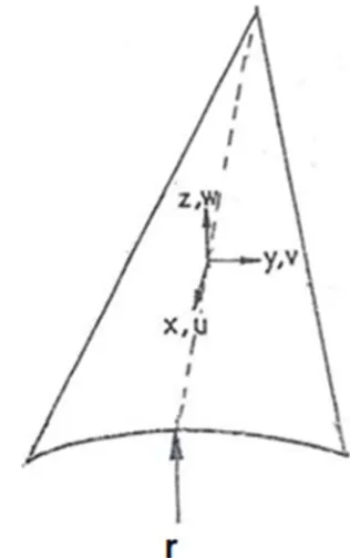
The strain displacement equations for a cylindrical shallow shell element in a system of coordinates as shown in Figure 1, are given by:
⁄
⁄ ⁄
⁄ ⁄
⁄ ⁄
2 ⁄ (1)
These strain components cannot be considered independent, for they are in terms of the three displacements and hence they must satisfy the compatibility equations. These are obtained by eliminating the displacements u, v and w from Eq. (1). Hence,
⁄ ⁄ ⁄ ⁄ 0
⁄ 2 ⁄ 0
⁄ 2 ⁄ 0 (2) In order to keep the element as simple as possible and to avoid the difficulties associated with internal additional degrees of freedom, the shell element is to have only five degrees of freedom at each of the three corners. These are
, , , / and / . Therefore, the shape functions should contain 15 independents constants. First the displacement fields corresponding to the rigid body modes are obtained by equating the six strains given in eq. (1) to zero and integrating the resulting differential equations. These give:
2 ⁄
⁄ ⁄ ⁄2
(3)
Since the element is to have 15 degrees of freedom, the remaining 9 constants are used to express the displacements corresponding to the straining of the element. These are apportioned among the strain as follows:
1 ⁄ ! ⁄2 ⁄6 ⁄2 ⁄ #6
$
!
# (4)
The un-bracketed terms are first assumed. Those for the membrane strains are suggested by the corresponding expressions given by the usual 6 degrees of freedom plane strain shape function. The terms in brackets are then added to satisfy the compatibility Eq. (2). Eq. (4) are the equated to the corresponding expressions in terms of u, v and w from Eq. (1) and the resulting equations are integrated to obtain:
$ ⁄2 ⁄120 ⁄12
$ ⁄2 ⁄6 ⁄24 ⁄24 ⁄4
! ⁄2 ⁄6 ⁄2 ⁄6
6
⁄ ⁄2 (5) The complement displacement functions are the sums of corresponding expressions from eqs. (3) and (5). Having derived the final expression for the displacement functions, it is now possible to obtain the elemental stiffness [K] for the cylindrical shell element in the usual manner using the following equations:
& '(#)*+ ,)-,d d . '#(
⁄ ⁄ ⁄ ⁄ 0
⁄ 2 ⁄ 0 (6)
Where , and - are the strain and rigidity matrices, respectively, and 'the matrix relating the nodal displacement to the constants to . , can be calculated from eqns (1), (3), (4) and D is given by substituting the matrices , and -into eqn (5). The integration within the bracketed terms of eqn (5) are carried out explicitly and the rest are computed to obtain the stiffness matrix [&].
3. Patch Test
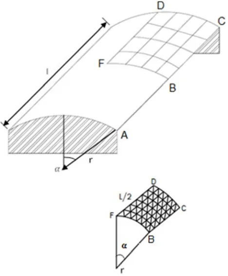
This test is to be considered which is frequently used to test the performance of the shell elements is that of roof having the geometry as shown in Fig. (2). The shell has the following dimensions and material properties: thickness, t= 0.0762 m, r= 7.62 m, L= 15.24 m, ∝ = 40°, modulus of elasticity, E= 2.106 x10⁷ kn/m2, Poisson’s ratio, 1= 0.3, the roof subjected to gravity load q= 4.393 kn/m2. The straight edges are free while the curved edges are supported on rigid diagrams along their plan considering the symmetry of the problem only one quarter of the roof is analyzed.
Figure 2. Geometry and finite element mesh of the shell roof.
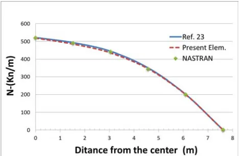
The results obtained by the new present element for the vertical displacement at the midpoint B of the free edge of the roof are compared to other kinds of shells elements Omurtag et al [23]; Altman et al [24] as shown in Table 1. Table 1 shows the new present element shows very good agreement. Further investigation is carried on the normal deflection along free ends of the shell roof and are shown in Figure 3, which indicates excellent agreement between the results obtained from the present element and the solution in reference [23].
Table 1. The vertical deflection at point B (W).
Mesh No. Ref. [23] Ref. [24] Present Element
2x3 -9.97 -8.59 -9.88
3x4 -10.40 -8.49 -10.39
4x4 -10.54 -- -10.52
4x5 -10.80 -8.87 -10.75
5x6 -10.80 -9.05 -10.80
Figure 3. Variation of vertical deflection, W, along B-C.
4. Stiffened Cylindrical Shell Roof
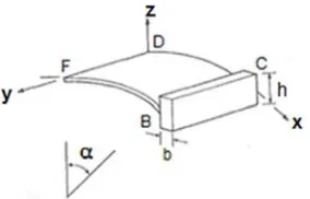
In practice, shells having large spans are stiffened by beams. The problem considered is an eccentrically stiffened shell structure as shown in Figure 4. This shell is chosen to be the same as the shell in the previous problem except for end stiffener at the free edge. The beam height, h= 0.5 m and the beam width b= 0.5 m. Materials properties of shell and beam are taken to be the same. For gravity loading of beam q= αA, where specific weight of the concrete equals α =24 kn/m2 and A is the cross-sectional area of the beam. Due to symmetry, one fourth of the system is used in the analysis.
Figure 4. Eccentrically stiffened shell roof.
Figure 5. Variation of the axial force resultant on the stiffener along B-C side.
Figure 6. Variation of the shearing force on the stiffener along B-C side.
Figure 7. Variation of the bending moments on the stiffener along BC side.
5. Parametric Studies
5.1. The Shell with Different Stiffener Depths
To investigate the effect of the depth of the beam stiffeners on the resulting internal forces (N, V, M) along the edge beam, three cases were considered h= 0.5 m, 1.0 m and 1.5 m, while the width, b, is kept at 0.5 m. The new triangular cylindrical finite element is used in the analysis. The Figures 8, 9 and 10 show the distribution of N, V and M along the beam respectively.
Figure 9 shows that the stiffeners sizes resulted in
significant change of the shearing and bending moment internal forces along the free edge. For example, the maximum shearing force (at the center) changed by 100% for the shallow beam and 200% for the deeper beam case, compared with the case of the original stiffened shell having 0.5m x 0.5m stiffeners. Similar observations can be made from Figure 10 with regard to the bending moment resultant M along BC. Likewise, the bending stress, M, has been chanaged significantly due to the use of the stiffeners as shown in Figure 10. A changing of about 150 % is achieved with the thinner beam and about 200 % with the thicker beam compared with the original stiffened shell.
Figure 8. Variation of the shearing force on the stiffener along B-C side.
Figure 9. Variation of the axial force resultant on the stiffener along B-C side.
5.2. The Shell with Different Axis Rotation
More parametric study is carried out to see the behaviour the previous stiffened problem (case 1) if it is stiffened by axis rotated (vertical) beam (case 2) at the free end. The layout and geometry of the problem considered are shown in Figure 11. The height and width of the beam kept the same (h= 0.5 m, b= 0.5 m).
Figure 11. Shell roof stiffened with vertical beam.
Figures 12, 13 and 14 show the distribution of N, V and M for the different axis rotation (case 1 and case 2) along the free edge beam respectively.
Figure 13 shows that the different axis rotation resulted in significant changing of shear force and bending moment resultants. For example, Figure 13 shows the direct shear resultant V has changed by about 50% when using case 1. Similar observations can be made from Figure 14 with regard to the bending moment resultant M along BC. Likewise, the bending stress, M, changing of about 300% is achieved with case 1.
Figure 12. Variation of the shearing force on the stiffener along B-C side.
Figure 13. Variation of the axial force resultant on the stiffener along B-C side.
Figure 14. Variation of the bending moments on the stiffener along BC side.
6. Conclusion
A new triangular strain-based finite cylindrical shell element is developed using shallow shell formulation. The element has the five degrees of freedom at each corner node.
The developed triangular cylindrical finite element is first applied to analysis of a barrel vault. The results for the deflections are presented and show that the developed element has very good agreement results. This element is then used to analyze a stiffened cylindrical shell roof.
The effect of the stiffener size and axis rotation on the various internal forces components is presented. A significant reduction is achieved in the shearing and bending moment forces by increasing the height of the stiffener and by rotation of the stiffener axis to vertical direction. This gives the designers an insight for the behaviour of such structures.
References
[1] Grafton P. E. and Strome. D. R., (1963), “Analysis of axisymmetric shells by the direct stiffness method” AIAA. J. (1), 2342-2347.
[2] Jones. R. E and Strome. D. R., (1966), “Direct stiffness method analysis of shells of revolution utilizing curved dements”, AIAA. J., (4), 15159-1525.
[3] Conner. J. J. and Brcbbia, C., (1967), “Stiffness matrix for shallow rectangular shell element”. J. Eng. Mech. Div. ASCE, 93. No. EMS, 41-65.
[4] Bogner. F. K., Fox. R. L. and Schmit. I. A., (1967), “A cylindrical shell discrete element”, J. AIAA., 5(4), 745-750. [5] Cantin. G and Clough. R. W., (1968), “A curved cylindrical
shell finite element” AIAA J. 16, 1057-1062.
[6] Sabir. A. B. and Lock A. C., (1972), “A curved cylindrical shell finite element” Int. J. Mech. Sci. 14, 125-135.
[7] Lindbergy. G. M. Cowper. G. R. and Olson. M. D., (1970), “A shallow shell finite element of triangular shape” Int. J. Solids struc. 14, 1133-1156.
[9] Ashwell. D. G. Sabir. A. B. and Roberts T. M., (1971), “Further studies in the application of curved finite element to circular studies” Int. J. Mech. Sci. 13. 507-517.
[10] Ashwell. D. G. and Sabir. A. B, (1972), “A new cylindrical shell finite element based on simple independent strain functions”. Int. J. Mech. Sci. 14.
[11] Sabir. A. B., (1975), “Stiffness matrices for general deformation (out of plane and in-plane) of curved beam members based on independent strain functions”, The Maths of Finite Elements and Applications II. Academic Press. 34, 411-421.
[12] Sabir. A. B. and Charchafchi. T. A, (1982), “Curved rectangular and general quadrilateral shell element for cylindrical shells” The Maths of Finite Elements and Applications IV. Academic Press 231-238.
[13] Sabir. A. B., (1983), “Strain based finite for the analysis of cylinders with holes and normally intersecting cylinders”. Nuclear Eng. and Design. 76. 111-120.
[14] Sabir. A B. (1987), “Strain based shallow spherical shell element” Proceedings Int. Conf. on the Mathematics of Finite Element and Applications, Bronel University.
[15] El-Erris, H. F., (1994), “Behavior of hipped roof structures”, Proc. 2nd. MCE Eng., CEI, Baghdad.
[16] El-Erris, H. F., (1995), “Effect of eccentricity of crown and edge beams on the behavior of hipped roof structures”, journal of military college of engineering, Baghdad.
[17] Mousa. A. I. and Sabir. A. B., (1994), “Finite element analysis
of fluted conical shell roof structures”. Computational structural engineering in practice. Civil Comp. Press, ISBN 0-948748-30-X pp 173-181.
[18] Mousa. A. I., (1998), “Finite element analysis of a gable shell roof” Advances in Civil and Structural of Engineering Computing for Paretic civil-comp press, 26-268.
[19] Mousa A. I, Aljuadi A. E, Kameshki E. Dahman, N, (2012), “New strain cylindrical rectangular finite element for the analysis of arch dam” Canadian Journal on Environment, Construction and Civil Engineering, Canada.
[20] Mousa, A, and Djoudi, M., (2015), “A shallow shell finite element for linear and nonlinear of spherical shells “International journal of engineering and scientific, IJENS. Vol.15, Issue 05, pp 24-29.
[21] Mousa, A. and Djoudi M, (2015), “New strain based triangular finite element for the vibration of circular cylindrical shell with oblique ends “. International journal of civil and environmental engineering, IJCEE. Vol. 15, Issue 05, pp 6-11.
[22] Mousa, A. and Kemeshki, E. (2017) “Strain based finite element for analysis of cylindrical dam”. American journal of engineering research (AJER). Vol.6. No. 2 ,pp
[23] Omurtag, and Akoz A., (1992), “Mixed finite element formulation of eccentrically stiffened cylindrical shells”. Computers &Structures, Vol. 42, No. 5 pp 751-768.