Development of a Helicon Plasma Source for the Measurement of
He
∗
Component in a He
0
Beam
Atsushi OKAMOTO, Keisuke IWAZAKI, Takehiro ISONO, Takashi KOBUCHI, Sumio KITAJIMA
and Mamiko SASAO
Tohoku University, Sendai, Miyagi 980-8579, Japan
(Received 10 March 2008/Accepted 12 September 2008)
A high density plasma source using helicon discharge was designed for the measurement of the population ratio of the metastable state and ground state in a helium neutral beam. The required density of the plasma source was investigated in terms of the rate coefficient relevant to the beam-plasma interaction. The charge-exchange for the metastable state is a dominant process in a beam-energy range of 30-300 keV for the beam attenuation, promising the measurement of the metastable fraction in the helium neutral beam using this plasma source. The first plasma with the electron density of 3.4×1012cm−3and the electron temperature of 10 eV was successfully
produced in argon gas.
c
2008 The Japan Society of Plasma Science and Nuclear Fusion Research
Keywords: helium beam, beam attenuation, metastable state, helicon plasma, high density plasma DOI: 10.1585/pfr.3.059
1. Introduction
In some types of plasma diagnostics, the production of atomic beams without the metastable states are required. Because in general the metastable atoms have lower ion-ization potentials than those of the ground state, beam at-tenuation can be stronger than expected without them. Re-cently, alpha particle diagnostics using a helium neutral beam were designed for the international thermonuclear fusion experimental reactor (ITER) [1]. In the method, the diagnostic beam neutralizes alpha particles by the double charge-exchange process; fast helium atoms are suitable as components of the diagnostic beam. The issue of the metastable state is thus considered to be unavoidable.
Sasao et al.[2] proposed a helium neutral beam for such a fast beam application, in which the helium neutral beam is produced not directly from the charge exchange of a positive beam but from autodetachment of a nega-tive ion beam, where the neganega-tive ion beam is converted from a positive ion beam through an alkali vapor cell [3,4]. In this method, almost all neutral helium atoms are ex-pected to be in a ground state [5]. However, few reports have experimentally verified a metastable fraction after au-todetachment. Experimental research has recently been started in which a helium neutral beam is produced using the above-described method for proof of principle [6, 7]. Evaluation of the metastable fraction in the helium neutral beam is a task in the proof of principle experiment. We have been developing two complementary methods. One is laser absorption spectroscopy using a diode laser [8, 9], which is more accurate for obtaining the absolute value of metastable population density. However, obtaining infor-author’s e-mail: [email protected]
mation on the ground state using the diode laser is difficult. The other method is measurement of beam attenuation in a plasma. The fraction of the metastable state in the he-lium neutral beam is deduced experimentally from beam attenuation. In comparison with the measurement of beam attenuation in a gas cell, the measurement in a plasma has an advantage; there is a larger reaction rate of electron stripping in the plasma than in the neutral gas in the same density. In terms of the availability of reliable collisional cross-sections with helium atom, helium plasma is suit-able for the attenuator. An issue in the plasma-attenuation method is production of a sufficiently dense plasma. Al-though many methods are available for the production of high density plasmas, the structure of electrode or antenna is limited so that the neutral beam can penetrate through the high density plasma. Helicon discharge using a cylin-drically or axially winded antenna [10–14] is a candidate of the plasma production, which produces high density plasma and enables the beam to pass through the plasma.
We have developed a high density plasma-source for the measurement of the metastable (He∗) component mixed in a ground state (He0) helium-neutral beam. In this paper, the calculation of beam attenuation in a plasma and development of the plasma source are described. Atomic processes resulting from a helium-neutral beam-injection into a helium plasma is described in Sec. 2, where the re-quirement on the target plasma is also considered. In the next section (Sec. 3), the design concept of an experimen-tal device is described. The experimenexperimen-tal result on plasma production is shown in Sec. 4, followed by a summary in Sec. 5.
c
2008 The Japan Society of Plasma
2. Requirement of the Target Plasma
Source
2.1
Beam attenuation in a plasma
The fraction of a metastable state, n∗/(n0+n∗) in a
helium neutral beam is derived from the beam intensity, wheren0 andn∗are the population density of the ground state and metastable state of the helium atoms. We can measure the total intensity of the mixture beam before and after passing through the target plasma, respectively;
I(0)=(n∗+n0)vb, (1)
and
I(l)=n∗exp−nTσvl/vb
+n0exp−nTσvl/vb
vb,
(2) wherevb,l,σv, andnTare the beam velocity, the length
of the plasma, rate coefficient of each reaction, and the tar-get density related to the reaction, respectively. The sum-mations in Eq. (2) are performed to all reactions related to the beam attenuation. While cross-sections of inelas-tic collisions are different between those for the ground state and those for the metastable state, the contribu-tion of elastic collision to the ground state beam and the metastable state beam is equivalent. Thus, attenuation fac-tors are introduced for the inelastic component of collision; α = inel.nTσvl/vb for the metastable beam, andβ =
inel.nTσvl/vb for the ground state beams, respectively.
On the other hand, the attenuation factor for the elastic component, γ = elasticnTσvl/vb, is a common factor.
The beam intensity after passing through the plasma is then
I(l)=n∗exp (−α) exp (−γ)+n0exp (−β) exp (−γ)vb.
Fi-nally, the fraction of the metastable state is obtained as fol-lows:
n∗ n0+n∗ =
exp(−β) exp(−γ)I(0)−I(l)
exp(−β)−exp(−α) exp(−γ)I(0). (3) From Eq. (3) we can see that the attenuation by elastic col-lision degrades the sensitivity of the measurement of the metastable fraction against beam attenuation.
2.2
Atomic processes
The helium neutral beam, which consists of ground state helium atoms (11S,He0) and metastable helium
atoms (23S,He∗), interact with ions, electrons, and atoms
in a plasma. The beam energy designed for the proof of principle experiment is approximately 100 keV. In the present study, helium plasma is considered to be an atten-uator because of the advantages in the production of high density plasma and in the availability of abundant atomic data. Thus, the target plasma consists of helium ions (He+), electrons (e), and residual helium atoms (He0). The
pres-ence of doubly charged helium ions (He2+) is negligible,
because low temperature (Te ∼ 10 eV) plasma is treated
in this paper. The population density of metastable states
in the residual atoms is also negligible compared with the plasma density. The atomic processes related to the inter-actions between the helium beam and the helium plasma are dominated by the following reactions.
The electron impact collisions result in ionization (Eqs. (4),(6)) or (de-)excitation (Eqs. (5),(7)) of the beam particle;
He0+e→He++2e, (4)
He0+e→He∗+e, (5)
He∗+e→He++2e, (6)
He∗+e→He0+e, (7)
where the first terms in the left hand side represent the beam component, which collide to the target as shown in the second term. The parameterized expressions of cross-sections for those reactions are taken from Ref. [15]. Al-though those reaction rates depend on electron tempera-ture, the variation of the electron temperature in the low temperature regime (Te∼5-10 eV) is not significant.
Some inelastic collisions by the ion impact result in electron stripping of the beam particle;
He0+He+→2He++e, (8)
He0+He+→He++He0, (9)
He∗+He+→2He++e, (10)
He∗+He+→He++He0,∗, (11) where Eqs. (8) and (10) stand for ionization, and Eqs. (9) and (11) stand for the charge exchange processes. The ion-ization cross-sections are obtained with the aid of mass ratio scaling; σi(E) = (me/Me)σe(E). The charge
ex-change between the ground state atom and ion (Eq. (9)) is represented by Ref. [16], whilen04-scaling [17] is used for
the charge exchange between the ion and metastable atom (Eq. (11)). Elastic collision by ion impact is described in the next paragraph. Although the ion impact excitations are not explicitly treated in this paper, the effect of those reactions is as small as the effect of the electron impact excitations.
Atom impact collisions (He0 +He0,He∗ +He0) are treated as elastic collisions. Part of the ion impact colli-sions (He0+He+,He∗+He+) also result in elastic colli-sions. For simple discussion, these elastic collisions are evaluated using Rutherford scattering cross-section. The cross-section for elastic collision is determined from the geometrical scattering angle.
The reaction rates σv of those interactions are derived from integration of the collisional cross-section in relative velocity space σ(v) for each atomic process;
σv = σ(v)vf(v)dv, where f(v) is the velocity
distri-bution function. As for interactions of the beam particle with ions and atoms in the plasma, the relative velocity is almost the same as the beam velocity. The reaction rates are then represented by σv = σ(vb)vb. On the
other hand, a beam velocity of 2.2×10⁶m/s, which
the electron thermal velocity in the electron temperature
Te=14 eV. In order to obtain the reaction rate for the
in-teractions with electrons, the relative velocity distribution function should be treated as a shifted Maxwellian. The re-action rates are calculated as a function of the beam energy. The result in a typical electron temperature (Te =10 eV)
is shown in Fig. 1. The reaction rate of electron impact (de-)excitation (11S −23S) in Fig. 1 (a) (Fig. 1 (b))
sug-gests that the (de-)excitation processes give a negligibly small contribution to the total reaction rate. The
ioniza-Fig. 1 (a) Rate coefficient for interactions between a ground
state helium atom beam and a helium plasma. Thin solid
line represents rate coefficient for charge-exchange
re-action (cx); dotted line, electron impact ionization (ei); broken line, ion impact ionization (ii); dashed-dotted line, electron impact excitation (ex); dashed-double dot-ted line, elastic scattering (el). Thick solid line represents
the total rate coefficient of electron loss. (b) The same as
(a) except that the beam component is in the metastable state and dashed-dotted line (ex) represents electron im-pact deexcitation to the ground state.
tion rate due to the ion impact is asymptotically close to that due to electron impact in the high energy range. The dashed-double dotted line represents the reaction rate of elastic collision between a beam particle and a target parti-cle. The line representing the elastic collision corresponds to that with a scattering angle ofχ=1.0×10⁻³radian.
When the beam energy is higher than 300 keV, the to-tal reaction rate for the ground state comes close to that for the metastable state. Thus, measuring the metastable fraction at that energy regime is difficult. On the other hand, in a lower energy regime (≤ 30 keV), the effect of elastic scattering is expected to reduce the signal to noise (S/N) ratio. Thus, the energy range 100-200 keV is suitable for the measurement. In this energy regime, the dominant process is charge exchange between the beam particle and the ion in the plasma for both the metastable and ground state beam. The total reaction rate of electron loss for the metastable beam (Fig. 1 (b)) is more than one order higher than that for ground state (Fig. 1 (a)) in this energy regime.
2.3
Result of the evaluation
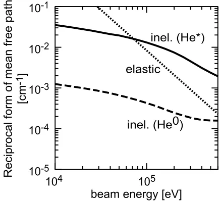
From the energy dependence of the rate coefficients described above, the mean free path of the total attenua-tion, (nTσv/vb)−1, is obtained. The reciprocal form of
the mean free path is plotted as a function of the beam en-ergy in Fig. 2. Because only the elastic collision includes neutral density in the target density,nT=ni+nn, the mean
free path of the elastic collision is a function of ionization degree as well as the ion density. Figure 2 is evaluated un-der the conditions;Te =10 eV,ne =ni = 2×1012cm−3,
andni +nn = 2×1013cm−3. If a target plasma density
nT = ne satisfies nelσv/vb ≥ 1, the beam suffers
nificant attenuation while passing through the lengthlof the plasma. In order to obtain a metastable fraction in the beam, at least the following condition should be satisfied for the metastable beam-component: nelσvmeta/vb ≥ 1.
Required density isne > 1−2×1012cm−3 because the
plasma length achieved in a laboratory is of the order of one-meter. Such plasma is obtained by elongating high density helicon plasma along the beam line.
The elastic collision is an undesirable process in terms of discriminating between the metastable and ground state beam-atom. Both neutral atoms and ions affect the elastic collision, while the charge exchange processes occur only in collisions with ion. Thus, a higher ionization degree of target plasma results in a more efficient charge exchange with the same elastic collision frequency, and is essential for a better S/N ratio in the measurement of the metastable population in the beam. Assuming 10 % of ionization de-gree, an operational gas pressure of about 0.1 Pa will be suitable for our experiment.
We choose helicon discharge for the plasma produc-tion method to achieve those condiproduc-tions. Helicon discharge is known as a method which easily produces high den-sity plasma with relatively low input power [10–14]. It has also been mentioned that the helicon plasma achieves a high ionization degree, which is an advantage for the target plasma of the beam-metastable population measurement.
3. Design of a Plasma Source
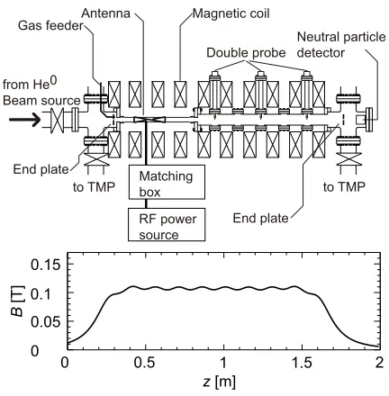
In order to achieve the plasma conditions evaluated in the previous section, a linear machine to produce a high density helicon plasma was designed and constructed at Tohoku University. It will be used as the main part of the diagnostic tool assisted by linear machine plasma for the helium atom beam (ALPHA). A schematic of the DT-ALPHA device is shown in Fig. 3. The total length of the device is about two meters. The DT-ALPHA device has 10 coils to produce a magnetic field with a one meter flat top region. The ripple of the magnetic field is suppressed below±3 % in the flat top region. Five power supplies (not shown in the figure) are equipped for the magnetic field production; each power supply is connected to two coils. The power supplies can be controlled independently, which enabled us to change the magnetic field configura-tion while maintaining port accessibility. The strength of the magnetic field applied at the center of the DT-ALPHA device is up toB0=0.2 T.
The vacuum chamber consists of a quartz pipe cou-pling an antenna to a plasma and a main chamber made of stainless steel. The inner diameter of the quartz pipe is 36 mm, which determines the plasma diameter. The main chamber has 20 ports to measure the plasma density pro-file and the beam attenuation. End-plates made of stain-less steel with a 10 mm diameter aperture in the center are equipped in both the upstream manifold and the down-stream manifold of the DT-ALPHA device. The end-plates
Fig. 3 Schematic of the DT-ALPHA device and a typical con-figuration of magnetic field.
are kept at the floating potential in order to suppress bipo-lar diffusion and to improve plasma confinement. They are also used to limit plasma elongation to keep the ax-ial density profile simple while a beam passes through the aperture of the end-plates.
Working gas controlled through the mass flow con-troller is fed from the upstream end-plate with a flow rate of up to 2.0 standard cubic centimeters per minute (sccm) for argon. Both ends of the DT-ALPHA device are equipped with turbo molecular pumps (TMPs). The up-stream TMP suppresses back-up-streaming of the gas into the beam duct, which is essential for extracting a stable beam of helium atom. The downstream TMP, which mainly evacuates the main chamber, is only used in the present experiment. A pressure of 0.18 Pa is then achieved in the chamber, which is consistent with the pressure estimated from the conductance of the main chamber.
A helical antenna (l=0.15 m) with a half wavelength
is used, which efficiently excites anm = +1 mode of the helicon wave. A 13.56 MHz oscillator with 3 kW maxi-mum power is connected to the antenna through a match-ing circuit. All these components are designed for steady state operation.
Measurements of the plasma parameters are per-formed using double probes installed in gauge ports (z =
4. Experimental Result
In order to test helicon-plasma production and to clean the chamber wall by discharge, argon gas was used for the first plasma experiment. The gas pressure in the main chamber was kept at 0.18 Pa. The magnetic field was var-ied fromB0 =0.05 T to 0.16 T in the center of the plasma.
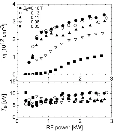
The electron temperature and density in the center of the plasma were measured as functions of the RF input power, and are shown in Fig. 4. A rapid increase of electron den-sity is observed around the RF power threshold of 400-600 W, except for the lowest magnetic field case. At a higher RF power than the threshold power, the density is kept over 1012cm−3 and gradually increases with the RF
power. The electron density of 3.4×1012cm−3is achieved
when the RF power is 2.8 kW and the magnetic field is 0.16 T. On the other hand, the electron temperature is al-most constant around 5-10 eV, especially in the high power region after the rapid increase of the electron density. The results suggest that the RF input power acts as a control knob for the electron density, keeping the electron temper-ature almost constant. Because it is an advantage to keep the reaction rate of electron impact ionization unchanged, high density plasma production with an almost constant electron temperature is a preferable experimental condi-tion.
The rapid increase of the electron density around the threshold power was investigated in various magnetic fields. The electron density is plotted as a function of the magnetic field in Fig. 5. The closed (open) circle in the figure indicates the experimental data obtained with the RF power higher (lower) than that corresponding to the
Fig. 4 Power dependence of electron density and temperature.
Argon gas pressure isp=0.18 Pa.
rapid increase. The dispersion relation of a plane wave in a cold uniform plasma is calculated. That for the minimum wave number (k=0.021cm−1) in the parallel direction, in which the half wavelength corresponds to the distance be-tween the end-plates, is also plotted in Fig. 5. The envelope of the minimum density over the rapid increase is matched with the dispersion relation of the helicon wave. When the parallel wave number increases (k >0.021cm−1), the
dis-persion curve shifts upward. Thus, the rapid increase of the electron density suggests the discharge transition from the inductively coupled mode to the helicon mode.
The radial profile of the electron density and temper-ature in the high density mode are shown in Fig. 6. The density distributions have peaked profiles. More than 90 % of the maximum density is kept insider ≤ 5 mm, the radius of which corresponds to the inspected beam radius. The density profile and characteristic radius are kept far from the antenna, although the peak density gradually de-creases with the distance from the antenna. On the other hand, the radial profile of the electron temperature is kept almost uniform insider ≤ 5 mm. The axial variation is also small. Sharp horns in the radial profile are observed atr18-20 mm, where the electron temperature increases up to 15 eV. Because the position corresponds to the inner surface of the quartz tube, the sharp horns might suggest the existence of energetic electrons produced by a strong field by the antenna. However, we will conduct a detailed investigation of the electron energy distribution in a future study.
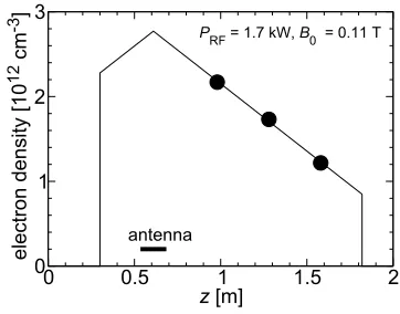
In order to evaluate the performance of the plasma as an attenuator of the helium neutral beam, the line-integrated density in the DT-ALPHA device is calculated. The axial density profile used in the calculation is shown in Fig. 7. The density profile is extrapolated from the peak
Fig. 5 Magnetic field dependence of electron density measured
atz =0.98 m,r =0 m. Plots correspond to experiment
with various RF power used. Solid line indicates disper-sion relation of a plane wave in a cold uniform plasma,
wherek =0.021 cm−1 andk
⊥ =1.3 cm−1are used for
Fig. 6 Radial profile of the electron density and temperature.
B0=0.11 T,p=0.18 Pa.
Fig. 7 Axial profile of the electron density. Plots indicate exper-imental results shown in Fig. 6. Thin solid line indicates an extrapolated density profile for the line-integrated den-sity calculation. Thick solid line indicates the position of the antenna.
density in Fig. 6 (a) using linear fitting assuming that the highest density is achieved below the antenna. The end-plates determine the boundary of the plasma. The
line-integrated density is then obtained by the integration: (line-integrated density)=
z2
z1
ne(z)dz, (12)
wherez1andz2 are positions of the end-plates. The
line-integrated density is 3.0×1014cm−2, which is twice as large
as that evaluated in Sec. 2. The result demonstrates that the plasma produced in the DT-ALPHA device has sufficiently high line-integrated density to measure the metastable frac-tion in the helium neutral beam. However, producing such a high line-integrated density-plasma using helium gas is not as easy as using argon gas. Higher ionization poten-tial is an expected cause. Improvement of the transmis-sion of RF power and diffusion-loss reduction, which we will work on in a future study, will play important roles in producing a high line-integrated density-plasma even in helium discharge.
5. Summary
Attenuation of a helium neutral beam in a helium plasma was evaluated. In a beam-energy range of 30-300 keV, atomic processes causing electron stripping from a metastable helium atom has a more than one order larger reaction rate than that from a ground state atom. Thus, the beam attenuation in the plasma will become a suitable method to measure the metastable fraction in the helium neutral beam. In order to realize the beam attenuation in the plasma, a high density plasma source has been de-signed and developed. The first plasma was successfully produced in argon. Rapid increase of the electron den-sity, which implies that the plasma is produced by heli-con discharge, was observed when the RF input power in-creased. The line-integrated density of an argon plasma is 3.0×1014cm−2, which is sufficient for the beam
attenua-tion.
Acknowledgments
This work was partly supported by the Ministry of Ed-ucation, Culture, Sports, Science and Technology of Japan (MEXT) Grant-in-Aid for Scientific Research on Priority Area of “Advanced Diagnostics for Burning Plasma Experiment” (442-16082201).
[1] M. Sasao, K. Shinto, M. Isobe, M. Nishiura, O. Kaneko, M. Wada, C.I. Walker, S. Kitajima, A. Okamoto, H. Sugawara, S. Takeuchi, N. Tanaka, H. Aoyama and M. Kisaki, Rev.
Sci. Instrum.77, 10F130 (2006).
[2] M. Sasao, A. Taniike, I. Nomura, M. Wada, H. Yamaoka
and M. Sato, Nucl. Fusion35, 1619 (1995).
[3] E.B. Hooper, Jr., P.A. Pincosy, P. Poulsen, C.F. Burrell,
L.R. Grisham and D.E. Post, Rev. Sci. Instrum.51, 1066
(1980).
[4] M. Sasao, A. Taniike, M. Nishiura and M. Wada, Rev. Sci.
Instrum.69, 1063 (1998).
[5] M. Sasao and K.N. Sato, Fusion Technol.10, 236 (1986).
and M. Wada, InProceedings of 2005 Particle Accelerator Conference, Knoxville, Tennessee(2005) p. 2630. [7] N. Tanaka, H. Sugawara, S. Takeuchi, S. Asakawa, A.
Okamoto, K. Shinto, S. Kitajima, M. Sasao and M. Wada,
Plasma Fusion Res.2, S1105 (2007).
[8] A. Okamoto, K. Shinto, S. Kitajima and M. Sasao, Plasma
Fusion Res.2, S1044 (2007).
[9] A. Okamoto, T. Kobuchi, S. Kitajima and M. Sasao, Plasma
Fusion Res.2, 029 (2007).
[10] R.W. Boswell, Plasma Phys. Control. Fusion 26, 1147
(1984).
[11] T. Shoji, Y. Sakawa, S. Nakazawa, K. Kadota and T. Sato,
Plasma Sources Sci. Technol.2, 5 (1993).
[12] S. Shinohara, Y. Miyauchi and Y. Kawai, Plasma Phys.
Control. Fusion37, 1015 (1995).
[13] F.F. Chen, Phys. Plasmas3, 1783 (1996).
[14] Y. Sakawa, T. Takino and T. Shoji, Phys. Plasmas6, 4759
(1999).
[15] T. Kato and R.K. Janev,Atomic and Plasma-Material
Inter-action Data for Fusion(Supplement to the journal Nuclear
Fusion)3, 33 (1992).
[16] R. Ito, T. Tabata, T. Shirai and R.A. Phaneuf, JAERI-M93,
117 (1993).
[17] R.K. Janev,Atomic and Plasma-Material Interaction Data