High-Performance Advanced
Discontinuous PWM Algorithm for Direct
Torque Controlled Induction Motor Drives
for Reduced Ripple.
O.CHANDRASEKHAR
Vignan’s Lara Institute of Technology & Science, Vadalamudi, Guntu, 522213,Andhara Pradesh
Dr.K.CHANDRA SEKHAR
R.V.R & J.C College of Engineering, Chowdavaram, Guntur, Andhara Pradesh
Abstract:
In this paper a high performance advanced discontinuous pulse width modulation (ADPWM) based direct torque controlled (DTC) induction motor drive operating at high line side voltages is proposed. The proposed ADPWM based IM drive uses a special category of sequences which not only reduces the switching losses but also reduces the line current distortion during high speed operations. However analysis in this paper is limited to harmonic ripple in line current and comparison of the proposed method is done with the conventional DTC (CDTC), conventional space vector pulse width modulation (CSVPWM) based DTC and clamping sequences based DTC. The proposed method uses a special category of DPWM sequences, 0121 and 7212. This category of DPWM sequences are referred as double switching clamping sequences as they not only clamp one of the phase to either of the buses but also switches one of the remaining two phases twice in every sub cycle. In this paper it is shown that, utilizing DPWM sequences and by changing the zero state at any spatial angle where is between 00 and 600an infinite number of ADPWM methods can be generated which are categorized as “continual clamping” and “split clamping” sequences. It will be shown that steady state line current distortion at higher line side voltages is reduced significantly compared with the CDTC, CSVPWM based DTC as well as the ADPWM based DTC using clamping sequences.
Keywords: Advanced Discontinuous PWM; conventional DTC; conventional space vector PWM.
1. Introduction
Induction motors are the workhorse of industry due to their simplicity and ruggedness. These motors can be fed from Current Source Inverters (CSI) or Voltage Source Inverters (VSI), and used as variable speed drives. Recent advances in semiconductor technology have led to new generations of fast-acting, power semiconductor switches like GTOs, MOSFETs, IGBTs, and more recently, IGCTs. The performance and characteristics of these switches strongly favour the VSI topology over the CSI one. This has been a major reason for VSI fed induction motor drives becoming more popular than CSI fed ones. Pulse width Modulation (PWM) strategies are required for switching the devices in a VSI appropriately to generate variable voltage, variable frequency, 3-phase AC required for the variable speed induction motor drive. At high power levels, the inverter can switch only at low frequencies, and the harmonic distortion is quite high. Hence, PWM strategies for high-power drives must aim at reducing the harmonic distortion, subject to low switching frequencies of the inverter. Development and analysis of such PWM strategies are carried out in this paper. Finally using the proposed ADPWM algorithm an optimal ADPWM based DTC IM drive operating at high line side voltages with reduced ripple is proposed.
high modulation range [4], [8-12]. This paper proposes an optimal ADPWM method using double switching clamping sequences which results in further reduction in line current harmonic distortion particularly at high modulation indices. This paper focuses on the generation of ADPWM methods, analysis of RMS stator flux ripple of some ADPWM methods [13]-[18]and finally ADPWM based DTC using the proposed algorithm is proposed. It is proven fact that double switching clamping sequences gives least ripple compared with CSVPWM, as well as clamping sequences [18]. Hence this is considered as an optimal ADPWM method in this perspective. With the proposed method it is proved that distortion in steady state line current at higher line side voltages is reduced significantly compared with the CDTC, CSVPWM based DTC as well as existing DPWM based DTC using clamping sequences.
2 .SVPWM based switching sequences
The space vector approach has become very popular over the last decade. In this approach, the reference is provided as a voltage space vector, which is sampled once in every sub cycle and an average vector equal to the sampled reference vector is generated by time-averaging of the different voltage vectors produced by the inverter [36,39-41,43-48].
According SVPWM algorithm the reference voltage vector is synthesized in an average sense using two near by active voltage vectors and two zero voltage vectors. With a three-phase voltage source inverter (VSI) there are eight possible switching states. The two states, from which no power gets transferred from source to load are termed as null vectors or zero states. The other six states called active states.
Fig1. Switching states and corresponding voltage vectors of a three phase VSI converter. I, II, III, IV, V, VI are the sectors.
It can be shown that all the six active states can be represented by space vectors given by (1) forming a regular hexagon dividing the space plane into six equal sectors denoted as I,II,III,IV,V,VI shown in Fig.1.
. 6 ,..., 2 , 1 , *
3
2 ( 1)3
k e V
Vk dc jk (1)
For a given reference voltage VREF making an angle with reference to V1 in first sector, the volt-time balance
is maintained by applying the active state1V1, active state2 V2 and two zero states V0 and V7 together for durations, T1,T2and TZrespectively, as given in (2) [3],[15]-[18].
s o o
T Sin
M
T *
60 ) 60 sin( * 1
(2)
s o T
M
T *
60 sin
sin * 2
(3)
2 1 T T T
TZ s (4)
where ‘M’ is the modulation index, given by M=
dc REF V V 2
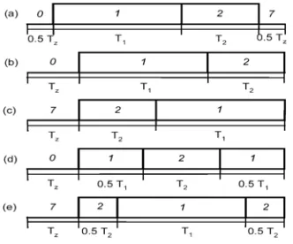
Fig. 2. CSVPWM and different DPWM sequences in sector-I.
Although according to CSVPWM strategy the two active vectors and two zero vectors must be applied for durations as in (2), these can be applied in different ways to generate different sequences. The rules that followed in SVPWM algorithm to synthesize the reference voltage vector are the nearest active voltage vectors must be applied, in every switching only one state should transform and in every sub cycle the sequence has to end up with same switching state that it starts with. Categorizing the sequences is based on these factors. First one is if two active states and two inactive states are used it is categorized as CSVPWM sequence, Second category is based on the fact that the total TZcan be spent in either V0 or V7state. The resultant sequences are
012,721 which are referred in this paper as bus clamping or DPWM sequences for the reason that one of the phase clamps to either of the bus in a sub cycle and its modulating waveforms are discontinuous. Lastly, based on the division of either of active voltage vectors duration the sequences are categorized as double switching bus-clamping sequences or double switching DPWM sequences, examples of which are 0121,7212,2721,1012. Since 2721, 1012 gives high ripple during high modulation regions they are not considered in further discussions. The considered switching sequences are shown in Fig.2 assuming the reference vector position in sector I.
Proposed ADPWM methods
In this paper to utilize the freedom of dividing the zero state duration a zero voltage vector distribution variable
is used to divide the zero state time between two zero states and are defined by (5).
T
ZT
0 (5)
1
7
T
ZT
(6)In DPWM methods the total zero state duration is spent in only one of the two zero states. Hence for,
0
Fig.3. Generation of space vector based ADPWM techniques (a) continual clamping and (b) split clamping.
To generate ADPWM methods in either of the two approaches, the constant variable can be applied at any spatial angle to yield different DPWM methods and when in case of continual and split clamping methods with 300 it results in ADPWM methods, i.e. two sequences 012 and 721 or 0121 and 7212 were used in each sector according to the set policy, which generates continual and split clamping methods as shown in the Fig.3. The same methodology results in the existing DPWM methods, well known by the names DPWM1, DPWM3 for 300[5] and for00or600it results in the existing DPWM methods renowned by the names DPWM2 and DPWM0[5].
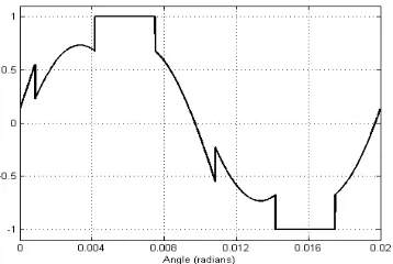
It is observed that the modulating waveforms of continual and split clamping do not differ with the clamping and double switching clamping sequences [16] ,[17]. The modulating waveforms of the above said methods are shown in Fig.4 for 0
45 .
Fig. 4a. Modulating waveforms of continual clamping with450.
Fig. 4b. Modulating waveforms of split clamping with 450
2.2 Analysis of RMS Stator Flux Ripple
According to space vector algorithm the reference voltage vector is synthesized in an average sense over a sampling period and not instantaneously. The difference between the reference voltage vector and the applied voltage vector is the instantaneous ripple vector. As the reference voltage vector rotates at synchronous speed, the instantaneous ripple vector changes its magnitude and direction. Resolving the ripple vector in a synchronously rotating d-q reference frame corresponding to the two active states and two zero states gives
D Q Q
1
1 cos ]
3 2
[ V V T
Q dc REF (7)
2 0
2 cos(60 ) ]
3 2
[ V V T
Q dc REF (8)
Z REF
Z V T
Q (9) 1
] sin 3 2
[ V T
D dc (10) REF
V and are assumed to be the same for all the sequences, but the carrier cycle duration is Tsfor
CSVPWM, 0121, and 7212 whereas it is 3 2Ts
for the sequences with 012 and 721.Neglecting the stator ohmic
drop time integral of the instantaneous ripple is proportional to the stator flux ripple and is a measure of ripple in line current [15]-[18]. The d and q-axis components of the stator flux ripple over a switching period corresponding to the CSVPWM, clamping sequences and double switching clamping sequences are as shown in Fig.5.
The RMS stator flux ripple over a sub cycle for the sequences CSVPWM, clamping sequences 012, 721 and the double switching clamping sequences 0121, 7212 are denoted by FCSVPWM2 ,F0122 ,F7212 ,F01212 ,F72122 respectively and are expressed as in (5). The RMS stator flux ripple for the clamping sequences based continual and split clamping methods and the proposed double switching clamping sequence based continual and split clamping methods are given in (6). Fig.6 shows the variation of RMS stator flux ripple over a sector with CSVPWM, and the proposed ADPWM methods at M=0.85.
S z Z CSVPWM T T Q F 2 ) 5 . 0 ( 3 1 2 2
S Z Z Z Z T T Q Q Q Q Q Q 1 2 1 1 2 ) 5 . 0 ( ) 5 . 0 ( 5 . 0 5 . 0 3 1
SZ Z Z Z T T Q Q Q Q Q Q 2 2 1 2 1 5 . 0 5 . 0 5 . 0 5 . 0 3 1
S Z Z T T Q 2 5 . 0 31 2
S T T T D2 1 2 274
(11)
S Z Z
T
T
Q
F
2
27
4
2 2 012
S Z Z Z Z T T Q Q Q Q Q Q 1 2 1 1 2 ) ( ) ( 27 4
S Z T T Q Q 12 2 27 4
S T T T D2 1 2 27 4 (12) S Z ZT
T
Q
F
2
27
4
2 2 721
S Z Z Z Z T T Q Q Q Q Q Q 2 2 2 2 2 ) ( ) ( 27 4
S Z T T Q Q 22 1 27 4
ST
T
T
D
2 1 227
4
(13) S z Z T T Q F 2 ) ( 3 1 2 2 0121
S Z Z Z Z T T Q Q Q Q Q Q 2 ) 5 . 0 ( ) 5 . 0 ( 3 1 1 2 1 1 2
SZ Z T T Q Q Q Q Q Q 2 2 1 1 1 2 1 5 . 0 5 . 0 5 . 0 5 . 0 3 1
S T T Q 2 5 . 0 31 2 1
1
S T T T D2 1 2 5. 0 3
1
(14)
S z Z T T Q F 2 ) ( 3 1 2 2 7212
S Z Z Z Z T T Q Q Q Q Q Q 2 ) 5 . 0 ( ) 5 . 0 ( 3 1 2 2 2 2 2
SZ Z T T Q Q Q Q Q Q 1 2 2 2 2 2 2 5 . 0 5 . 0 5 . 0 5 . 0 3 1
S T T Q 2 5 . 0 31 2 2
2
ST
T
T
D
2 1 25
.
0
3
1
(15)Fig. 6. RMS stator flux ripple within a sector for a) AB-proposed continual clamping method for 0
30
b) CD- proposed split clamping method for 0
30
c) AD- proposed continual clamping method for 0
60
d) CB- proposed split clamping method for 0
0
Fig.7. Analytical evaluation of RMS stator flux ripple against modulation index at switching frequency of 5 KHz. a) CSVPWM b) clamping sequences and c) proposed clamping sequences.
0 2 012 0 2 721 2 60 , 0 , ) ( F F clamping
FCONT (16)
0 2 721 0 2 012 2 60 , 0 , ) ( F F clamping
FSPLIT (17)
0 2 0121 0 2 7212 2 60 , 0 , ) ( F F proposed
FCONT (18)
0 2 7212 0 2 0121 2 60 , 0 , ) ( F F proposed
FSPLIT (19)
The RMS stator flux ripple due to CSVPWM, clamping sequences based ADPWM methods and the proposed ADPWM methods with respect to M are compared at 0
30
, and are shown in Fig.7. It is observed that though the proposed sequences give high ripple when compared to CSVPWM and clamping sequence based DPWM methods at low modulation indices, gives least ripple after a modulation index of 0.744.
3. Proposed DTC Induction Motor Drive
The block diagram of the proposed ADPWM based DTC is shown in the Fig.8. With the proposed method ripples in torque and flux at high modulation indices are reduced significantly maintaining constant switching frequency.
The proposed DTC retains all the advantages of the CDTC, in addition to this gives enhanced performance in high modulation regions which is a limitation with CSVPWM based DTC. Addition of slip speed to the actual speed generated by the adaptive motor model block generates reference stator flux vector. The reference d and q axis voltages are calculated by the reference voltage vector calculator using the equations given in 20,21,22,and 23. Taking these two as inputs the magnitude and position of the reference voltage vector are calculated and according to the set value of
the ADPWM block generates gating pulses to the inverter based on space vector approach. The adaptive motor model estimates the torque and speed from the d and q axis voltages and currents. The dynamic model of the induction motor is modeled in stationary reference frame.s ds ds s ds
T i R
V* (20)
s qs qs s qs
T i R
V* (21)
Where
ds ds
ds
* (22)
qs qs
qs
*
(23)
4. Simulation Results and Discussion
Simulation of the proposed DTC controlled induction motor drive is done in MATLAB/SIMULINK environment. Simulation is done using fixed step solver with a step size of 10e-6. The starting torque is limited to 15.8 N-m. Simulation is done on a 3-
induction motor rated at 1.5KW, 1440rpm, four pole, having thefollowing parameters: Rs=7.83
, Rr=7.55
, Ls=0.4751H, Lr=0.4751H, Lm= 0.45351H, J=0.06Kg.m2 . From the simulation results shown it can be observed that compared with CSVPWM and ADPWM methods using clamping sequences the proposed ADPWM methods results in least harmonic distortion when the drive is operating at near rated speeds. Reduction in stator current ripple can be achieved with the proposed split clamping PWM technique and analytically it is clear that with 30o, split clamping gives minimum distortion and hence this method is considered as an optimal ADPWM method for the drives operating at near rated speeds. Fig.9- Fig.10 shows the no-load starting and steady state transients in three phase stator currents, torque, speed and stator flux of the CDTC and CSVPWM based DTC induction motor drive. Measured no-load steady state current waveform and its harmonic spectra are also presented for comparison. Fig.11 and Fig.12 shows the simulation results of the split clamping ADPWM based DTC drive using DPWM sequences 012 and721(with 30o) and double switching clamping sequences 0121 and 7212 (with 30o) respectively. Elaborated simulation results for the above said ADPWM based DTC IM drive showing different conditions like starting transients, steady state transients, and transients during step change in load, during speed reversal are presented. It is observed that with the proposed method %THD in line current is reduced significantly. Also, observations from the harmonic spectra reveal that with the CDTC method lower order harmonics dominate whereas with the proposed SVPWM method the dominant harmonic components are around the multiples of the switching frequencies. Also with the proposed methods because of usage of DPWM sequences reduction in inverter switching losses can be achieved (though not discussed in this paper). Fig.12f shows the locus of stator flux with the proposed method at high speeds.
Fig.9b. CDTC: Steady state transients.
Fig.9c. CDTC: Measured no-load steady state current and harmonic spectra (% of fundamental).
Fig.10b. CSVPWM based DTC: Steady state transients.
Fig.10c. CSVPWM based DTC: No-load steady state line current harmonic spectra (% of fundamental).
Fig.11b. Split clamping ADPWM based DTC using DPWM sequences 012 and 721(with 30o): Steady state transients.
Fig.11d. Split clamping ADPWM based DTC using DPWM sequences 012 and 721(with30o): Transients during reversal of speed (speed reversal command is given at 1.8 sec to change the speed from +1300 rpm to -1300 rpm).
Fig.12a. Proposed ADPWM based DTC using DPWM sequences 0121 and 7212: No load starting transients.
Fig.12c. Proposed ADPWM based DTC: Transients during step change in load (A load of 10N-m is applied at 1sec and removed at 1.4 sec).
Fig.12e. Proposed ADPWM based DTC using DPWM sequences 0121 and 7212: No-load steady state line current harmonic spectra (% of fundamental).
12f. Proposed ADPWM based DTC using DPWM sequences 0121 and 7212: locus of stator flux.
5.Conclusions
CDTC, though simple, because of the limitations like steady state ripple in torque and flux, variable switching frequency, search for PWM technique that gives an apt solution is one of the fascinating areas for researchers. SVPWM based DTC gave answer to some tribulations and now the search on how to reduce the ripple in line current particularly in high modulation regions. DPWM techniques can be used effectively to reduce either the switching losses or the harmonic distortion as may be required. The DPWM sequences can also be used effectively to reduce the harmonic distortion and their undesirable effects in the higher speed ranges of the drive. The triplen frequency components, required in all the above DPWM methods, can be generated using the 3-phase sinusoidal modulating waves themselves. In this paper with a special category of DPWM sequences an optimal ADPWM based DTC induction motor drive is proposed which can exercise a particular value of or might select according to a set policy. It is shown that split claming gives minimum ripple than with continual, CSVPWM as well as the ADPWM methods using clamping sequences predominantly in high modulation regions. Since the proposed split clamping with 300gives minimum ripple, which in this context referred as
an optimal ADPWM method is proposed for the drive operating at high line side voltages or near rated speeds. Simulation results conclude that with the proposed PWM method ripple in steady state line current is reduced significantly when compared with CDTC, CSVPWM based DTC, and ADPWM based DTC using clamping sequences.
Acknowledgements
References
[1] P.Titinen, m.Surandra, “The next generation motor control method , DTC Direct Torque Control,” IEEE proc on Power Electronics,Drives and Energy sysyems for Industrial growth, Vol 1,pp 37-43, 1996.
[2] Thomas G.Habetler, et,al, “Direct Torque control of induction Machines using space Vector Modulation” ,IEEE Trans Industrial Applications ,Vol 28,No.5, pp 1045-1053,Sep/Oct 1992.
[3] L.Tang, L.Zhong, M.F.Rahman, Y.Hu, “An investigation of a modified direct torque control strategy for flux and torque ripple reduction for induction machine drive system with fixed switching frequency” IEEEIAS, pp. 837-844, 2002.
[4] Ahmet M. Hava, Russel J. Kerkman and Thomas A. Lipo, “A High Performance Generalized Discontinuous PWM Algorithm”, IEEE Trans Ind Appl, Vol34, No.5, pp.1059-1071September/October 1998.
[5] Ahmet M. Hava, Russel J. Kerkman and Thomas A. Lipo, “Simple Analytical and Graphical Methods for Carrier –Based PWM-VSI Drives”, IEEE Trans.PowerElectronics, vol4,no.1,pp.49-61,Jan,1999.
[6] Olorunfemi Ojo, “The generalized discontinuous PWM scheme for three-phase voltage source inverters” IEEE Trans. Ind. Electron., vol. 51, no. 6, pp. 1280-1289, Dec 2004.
[7] T. Brahmananda Reddy, J. Amarnath, D. Subba Rayudu and Md. Haseeb Khan, “Generalized Discontinuous PWM Based Direct Torque Controlled Induction Motor Drive with a Sliding Mode Speed Controller” IEEE Proc. Power Electronics, Drives and Energy systems for Industrial Growth, PEDES’06, New Delhi, India, paper no. 3D-11, Dec, 2006
[8] J.Holtz, “Pulsewidth modulation -A survey,” IEEE Trans Ind. Electronics.,”vol. 39, no. 5, pp. 410–420, Dec. 1992. [9] J.Holtz, “Pulsewidth modulation for electronic power conversion,”Proc.IEEE, vol 82,no.8,pp. 1194-1214, Aug. 1994.
[10] G. Narayanan and V. T. Ranganathan, “Synchronised PWM strategies based on space vector approach. Part 1: Principles of waveform generation,”Proc. Inst. Elect. Eng., vol. 146, no. 3, pp. 267–275, May 1999.
[11] K. Zhou and D.Wang, “Relationship between space-vector modulation and three-phase carrier-based PWM: A comprehensive analysis,” IEEE Trans Ind. Electron., vol. 49, no. 1, pp. 186–196, Feb. 2002.
[12] D. G. Holmes and T. A. Lipo, Pulse Width Modulation for Power Converters: Principle and Practice. New York: Wiley, 2003. [13] H. W. Van der Broeck, “Analysis of the harmonics in voltage fed inverter drives caused by PWM schemes with discontinuous
switching operation,” in Proc. EPE’91, Firenze, Italy, 1991, pp. 261–266.
[14] S. Fukuda and K. Suzuki, “Harmonic evaluation of two-level carrier based PWM methods,” in Proc. EPE’97, Trondheim, Norway, 1997, pp. 331–336.
[15] G. Narayanan and V. T. Ranganathan, “Analytical evaluation of harmonic distortion in PWM AC drives using the notion of stator flux ripple,” IEEE Trans. Power Electron., vol. 20, no. 2, pp. 466–474, Mar.2005.
[16] T. Brahmananda Reddy, J. Amarnath and D. Subba Rayudu, “Direct Torque Control of Induction Motor Based on Hybrid PWM Method for Reduced Current Ripple: A sliding Mode Control Approach” ACSE Journal, Volume (6), Issue (4), Dec., 2006, Paper nos. 23-30.
[17] T. Brahmananda Reddy, J. Amarnath and D. Subba Rayudu, “New Hybrid SVPWM Methods for Direct Torque Controlled Induction Motor Drive for Reduced Current Ripple” IEEE Proc. Power Electronics, Drives and Energy systems for Industrial Growth, PEDES’06, New Delhi, India, Paper no. 3B-20, Dec, 2006.