MODELLING AND CONTROLLING OF
INDUCTION MOTOR
BY USING LINEAR ADRC
CH. NAGA KOTI KUMAR, DR. P. LINGA REDDY, TRINATH.K, S.SUNDEEP, A. SATEESH KUMAR
DEPARTMENT OF EEE, K L University, Vaddeswaram, Guntur, Andhra Pradesh, India.
Abstract-
In this paper we present a new novel approach for the speed control of an IM using Linear Active Disturbance Rejection Controller [LADRC]. The field oriented control of IM needs the accurate mathematical model of IM, but it is very difficult to develop an accurate mathematical model. The LADRC does depend on the mathematical model so it is very robust to changes in plant parameters. This controller can also estimate and compensate the general disturbances which include the unknown internal dynamics and external disturbances by using the Extended State Observer, which can reduce the system to a linear one.
Index Terms: Linear ADRC, Linear Extended State Observer, Induction Motor and Control System.
1. INTRODUCTION
Currently the main types of electric motors are still the same DC, AC Asynchronous and Synchronous motors. But, since its invention, the AC asynchronous motor, also named induction motor, has become the most widespread electrical motor in use today. Induction machine (IM) has been the work-horse of industry due to its robustness, low cost, and less maintenance. The main advantage is that induction motors do not require any electrical connection between stationary and rotating parts of the motor. Therefore, they do not need any mechanical commutator (brushes), leading to the fact that they are maintenance free motors [1]. Induction motors also have low weight and inertia, high efficiency and high over load capability. Furthermore, the motor can work in explosive environments, because no sparks are produced.
Induction motors have many advantages compared to DC machines and synchronous machines inmany aspects, such as size, efficiency, cost, life span and maintainability. Low cost and ease of manufacturing have made induction machines a good choice for electric and hybrid vehicles. However, one must be able to achieve energy regenerative braking and be able to control the torque and speed of an induction machine at low speeds in order to use an induction machine in traction drives such as hybrid electric vehicles. Before going to analyze any motor or generator, it is very much important to obtain the machine in terms of equivalent mathematical equations [2], [3]. Traditional per phase equivalent circuit has been widely used in steady state analysis and design of induction motor.
Control of IM is considerably more complex than those of DC drives and this complexity increases substantially if high performances are required. The control is possible now-a-days due to the introduction of micro-controllers and high switching frequency semiconductor devices with the use of these devices the frequency, phase, magnitude of the input to the IM can be controlled and hence the motor’s speed and torque can be controlled [4], [5]. Various control techniques for the control of IM have been proposed. The main objective of a control technique is toobtain good dynamic performance and reliability under all load conditions.
Field weakening region operation can be divided into two distinct regions. The first region begins at base speed and ends at speed when current limits are unachievable due to voltage limits. The second region extends beyond the first region with voltage limit overriding the current limit and forcing a reduction in stator current. The main drawback of this method is that it causes high torque and flux magnitude errors, relatively low dynamic performance due to the PI current regulator.
Direct Torque Control (DTC) is an optimized AC drives control principle where inverter switching directly controls the motor variables: flux and torque. The measured input values to the DTC control are motor current and voltage [7]. The voltage is defined from the DC-bus voltage and inverter switch positions. The voltage and current signals are inputs to an accurate motor modelwhich produces an exact actual value of stator flux and torque. Motor torque and flux two-level comparatorscompare the actual values to the reference values produced by torque and flux reference controllers.
In the Direct Torque Controlled (DTC) method induction motor is supplied by a voltage source inverter [8]. It is possible to control directly the stator flux linkage (or rotor flux linkage, or magnetizing flux linkage) and the electromagnetic torque by the selection of optimum inverter switching modes. This selection is made to restrict the flux and torque errors within respective flux and torque hysteresis bands, to obtain fast torque response, low inverter switching frequency, and low harmonic losses.
Using the space-vector modulation (SVM) [9], instead of the DTC switching logic, provides higher control resolution and helps improving the drive’s behavior. Drives with SVM display excellent performance in terms of low torque ripple and quiet operation. The switching frequency results constant and the switching pattern can be further optimized. Attempts to combine the DTC with SVM have led to new schemes. Moderate torque ripple reduction is reported by using discrete SVM with predefined time intervals and extended switching tables. Linear proportional–integral (PI) torque and flux control using SVM is investigated and smooth operation was obtained in the steady state, but the robustness is low due to the linear control. The drawback of high current distortion, high torque ripple is eliminated in this method. But the control algorithm in this method is very complex compared to other control schemes.
A proportional–integral–derivative controller (PID controller) is a generic control loop feedback mechanism (controller) widely used in industrial control systems – a PID is the most commonly used feedback controller. A PID controller calculates an "error" value as the difference between a measured process variable and a desired set point valve. The controller attempts to minimize the error by adjusting the process control inputs. In the absence of knowledge of the underlying process, a PID controller is the best controller. However, for best performance, the PID parameters used in the calculation must be tuned according to the nature of the system – while the design is generic, the parameters depend on the specific system. The main disadvantage of PID controller is PID can lead to the overshoot of output, and derivative of PID is not realized physically.
2. PROBLEM FORMULATION
Although the speed control of dc motor is simple, it possess some difficulties like frequent maintenance, very expensive, requires very efficient cooling systems and also requires a very large size motor when compared to ac motor for the same amount of torque, so the motion control of induction motor has been the focus of the researchers [10]. The speed control of induction motor has become complex because of three issues listed. 1) The dynamical system is nonlinear. 2) Two of the state variables (rotor fluxes/currents) are not usually measurable. 3) Due to heating, the rotor resistance varies considerably with a significant impact on the system dynamics.
A simple way of controlling the induction motor is to adjust the magnitude of the stator voltage proportionally to a reference frequency. This open-loop method, known as the scalar control or the constant voltage-per-hertz control, is still used in low-cost frequency converters due to its important advantages. A speed sensor (which is expensive, fragile, and requires extra cabling) is not needed. The knowledge of motor parameters is not necessary either, implying that the method is robust. In addition, a scalar controlled frequency converter can feed several motors connected in parallel. However, the dynamic performance and the speed accuracy are poor, even if compensation for the stator resistance voltage drop and slip compensation are used. Furthermore, oscillations at light loads may occur. The PID controller is often used in control of inductor motor; however, it is easily affected by the changes of the parameters of a system. To overcome this problems this paper presents a new concept called Linear Active Disturbance Rejection Controller (LADRC).
3. LINEAR ADRC
has better static and dynamic performances, strong robustness and adaptability. The main objective of this control technique is toobtain good dynamic performance.
Although ADRC is superior to the classic PID, the number of tuning parameters increases. The tuning methods are too complex to be used in practice. ADRC consists of three parts: Tracking Differentiator (TD), Extended State Observer (ESO) and Nonlinear PD [12], [13]. TD are used as a profile generator which generates the desired output trajectory and its derivative .They are then compared to the filtered output and its derivative which makes it much less sensitive to noises. The purpose is to make the control design and tuning of the induction motor more easy and effective.
Rotor flux observation is the key step in implementation of field-oriented control system. It is used to observe rotor flux and robust to rotor resistance. ADRC and PI regulator is proposed to realize the speed control of induction motor. It maintains the advantages of the ADRC [14], and also reduces the number of the parameters needed to be tuned. The linear active disturbance rejection controller (LADRC) was introduced to control the induction motor. The block diagram of LADRC is shown in Fig1. In that the linear extended state observer (LESO) is used to observe rotor flux and it is robust to rotor resistance. Here the purpose of LADRC is to make the control design and tuning of the induction motor more easy and effective. But ADRC is a third order controller; hence its design is very difficult and complicated to develop. In order to reduce the complexity developed a new controller called Linear ADRC which is a linear controller, without any comprise with the performance compared to ADRC.
Fig 1. Block Diagram of LADRC
4. MATHEMATICAL MODEL OF LADRC
The system equation [10 - 14] can be written as
(1)
Where
y u w
, ,
are output, input and disturbances respectively.Let
b
b
0, one can have:0
y
f
b u
(2)Let
x
1
y
v x
,
2
f
The plant equation (2) can be written in state space form:
1 2 0
2
x x b u
x h
(3)
i.e.,
x A x B u E h v C x
(4)
5. LINEAR EXTENDED STATE OBSERVER DESIGN From the Fig 1
Let
z
1
v z
ˆ,
2
f
ˆ
. The extended state observer for the plant can be designed as
1 2 0 1 1
2 2 1
1
ˆ
z z b u l v z
z l v z
v z
(5)
i.e.,
1
(
)
ˆ
z
Az
Bu
L v
z
Where
1 2
l L
l
(7)
The characteristic polynomial of
A
e is2 2
1 2 0
( )s s l s l (s )
(8)
Where
0is the bandwidth of the observer.where
l
1
2
o,
l
2
o2. (9)6. CONTROLLER DESIGN
From the Fig 1 Let the control law be
u
(
z
2u
0) /
b
0 (10) Now the plant is reduced to0
y
u
(11)As long as
f
ˆ
can be fast enough to estimate f accurately.For equation (11), it can be easily controlled by a PD controller as follows:
0 p
(
)
d 1u
k r y
k z
(12)and
k
d
2
c,
k
p
c2 (13)Where
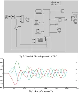
cis the bandwidth of the controller. 7. SIMULATION RESULTSTo verify the performance of the system, the proposed LADRC has been simulated with load, variations of rotor resistance and in Mat lab/Simulink.
Fig 2: Simulink Block diagram of LADRC
0 20 40 60 80 100 120 140
-800 -600 -400 -200 0 200 400 600 800
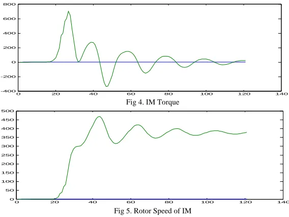
0 20 40 60 80 100 120 140 -400
-200 0 200 400 600 800
Fig 4. IM Torque
0 20 40 60 80 100 120 140
0 50 100 150 200 250 300 350 400 450 500
Fig 5. Rotor Speed of IM 8. CONCLUSION
In this paper, LADRC is used to control the inductor motor. It is not overly dependent on the accurate mathematical model of motor, so the system is inherently robust, and it can estimate and compensate the general disturbance that includes the unknown internal dynamics and the external disturbance (change of resistance for heating), so the complex control of inductor motor is simplified to the liner control.
9. REFERENCES
[1] Dave Rapini. “New directions in motor control”. Motion Control, Jan./Feb. 1999, pp.37-38. [2] B.K.Bose “Modern Power Electronics and AC Drives”, Prentice Hall, 2002.
[3] Paul C.Krause, Oleg Wasynczuk, Scott D.Sudhoff “Analysis of Electric Machinery & Drive system. [4] M.Riaz, “Simulation of Electrical Machine and Drive Systems Using Mat lab and Simulink”. [5] Barak Ozpineci and Lenon M Tolbert, “Simlink Implementation of Induction Machine Model”, IEEE.
[6] Chunting- Mi, John Shen, Narasitnhamurthi Nataraian, Mariano Filippa “ Field-Oriented Control of Induction Motors with Direct Rotor Current Estimation” IEEE Xplore, 2010, pp 389 – 392.
[7] M.Vasudevan and Dr.R.Arumugam “New Direct Torque Control Scheme of Induction Motor for Electric Vehicles”.
[8] H.F. Abdul Wahab and H. Sanusi “Simulink Model of Direct Torque Control of Induction Machine” American Journal of Applied Sciences 5, pp 1083-1090, 2008.
[9] Cristian Lascu, Ion Boldea and Frede Blaabjerg “Direct Torque Control of Sensorless Induction Motor Drives: A Sliding-Mode Approach” IEEE transactions on industry applications, vol. 40, no. 2, march/april 2004.
[10] Liying Liu1, 2, Zhenlin Xu1, Qiang Mei1 “A Sensorless Vector Control Induction Motor Drive Based on ADRC and Flux Observer” IEEE Xplore, CCDC 2009, pp 945- 948.
[11] J. Q. Han. “Auto-disturbance rejection controller and its applications,” Control and Decision, vol. 13, Jan. 1998, pp. 19-23.
[12] Z. Q. Gao, S. H. Hu, F. J. Jiang. “A novel motion control design approach based on active disturbance rejection,” Proceedings of IEEE Conference on Decision and Control, Dec. 2001, pp. 4877-4882.
[13] Liying Liu, Zhenlin Xu, Qiang Mei. “A Sensorless Vector Control Induction Motor Drive Based on ADRC and Flux Observer”. [14] Liying Liu, Zhenlin Xu, Qiang Mei. “Induction Motor Drive System Based on ADRCand PI Regulator”.
1
Ch. Naga Koti Kumar received the B.Tech in Electrical Engineering from JNTU Kakinada & M.Tech in Power Electronics and Power Systems from K.L.University Vijayawada. He published some research papers in international conference and national conference.
2
3
Trinath.K received the B.Tech in Electrical Engineering from JNTU Kakinada & M.Tech in Power Electronics & Power Systems from K.L University Vijayawada. He published many research papers in international conference.
4
Sundeep.S, received the B.Tech in Electrical Engineering from JNTU Hyderabad and M.Tech in Power Electronics and Power Systems from K.L University Vijayawada. He published many research papers in international conference and national conference.
5