e-ISSN: 2278-7461, p-ISSN: 2319-6491
Volume 5, Issue 5 [May. 2016] PP: 87-94
Design And Implementation Of Autopilopt For Mav
1
M Sandhya Rani,
2K Santhosh Kumar
1,2Assistant Professor, Department of ECE, Holy Mary Institute of Technology and Science
Abstract:- The performance of an autopilot controller has been an issue for industries over these days as they make use of less effective microcontroller. This limitation can be overcome by using FreeRTOS based implementation logic and by replacing less effective microcontroller with STM32 microcontroller. The prime objective of this paper is the development of FreeRTOS based autopilot controller using STM32.this autopilot controller comprises of Global Positioning System (GPS), Sensor Suite, external flash for data logging, Servo motor to control aileron, rudder and elevator action and MAVLink based transceiver in order to communicate between Micro Aerial Vehicle (MAV) and Ground Control station (GCS).this system focuses not only on device monitoring but also controlling it. The GCS comprises of Mission Planer software which is used to monitor the data received from MAV and can also control the flight mode from it. The Radio Frequency (RF) joystick is used for MAV‟s flight control.
Key Words: Autopilot controller, Free Real time operating system (FreeRTOS), STM32, GPS, MAVLink, MAV,
GCS, Mission Planer, RF.etc…….
I.
INTRODUCTION
Since the concept of MAV was proposed a few decades ago, Micro Aerial Vehicles (MAVs) have attracted a lot of interest from researchers all over the world. Many kinds of MAV prototypes have been developed by universities and research laboratories. The primarily goal is to make the MAV have as much functions as possible and suitable for different missions.MAV can significantly reduce the risk to human life and minimize the economic damage in the scientific, military and civil application. The vertical take- off and landing (VTOL) MAVs are particularly useful in missions such as surveillance and reconnaissance, homeland security, precision target location, signals intelligence, digital mapping, forest fire monitoring, and indoor rescuing. Since the miniaturization of Sensors, advances in communication devices and battery Technology, MAVs are becoming much smaller in size, Lighter In weight and can perform completely new missions such as operation at street level in urban environments [1]. Autopilots are systems to guide the UAVs in flight without Assistance from human operators. The autopilot technology of MAVs has become a hot research point in the field since the Constraints of their sizes and costs [2]. Nowadays, Technological advances in wireless networks and micro electromechanical systems (MEMS) make it possible to use Small autopilots on MAVs [3]. These autopilots have characteristics of small size, low power, and high integration; basically meet the requirements of guiding a single MAV in all stages including take-off, ascent, descent, trajectory following, and landing.
This paper focuses on the design and development of autopilot suitable for Micro Aerial Vehicles (MAVs). The autopilot design solves the problems of autonomous control, navigation without the human intervention. Autopilot design for MAV‟s is designed to be very small and they usually have battery as their power source. The autopilot board has onboard processors and sensors. These sensors are usually MEMS (Micro Electro-Mechanical Systems), because such size and weight is always a limiting factor in MAV‟s. These sensors collect the flight data like acceleration, velocity, altitude, pressure and temperature. These parameters are fed to the onboard computer. The onboard computer also has a data link to a ground station called Ground Control Station (GCS) from where the user sends commands to the MAV. Based on these commands and the data collected the MAV flies and complete its mission. Other innumerous applications of MAV‟s have also been implemented. It also finds use in space missions. MAV‟s usually carry a camera, a night vision device, a GPS and if possible an autopilot. Autopilot is needed when the data link between the MAV and the ground station is broken, otherwise MAV would fall from the sky.
II.
SYSTEM DESIGN
2.1 Autopilot Controller
The arm core present in the STM32F4 microcontroller provides the platform for complete Autopilot controller. Fig1 depicts the working of Autopilot controller. The Autopilot controller is used to control the trajectory of the MAV without requiring constant control by a human operator. Autopilot cannot replace human operator but help them in controlling the MAV and allowing them to focus on other operations such as monitoring the weather, trajectory and so on. The gains for autopilot were based on the flight parameters. Unfortunately mathematical model describing the flight dynamics of the MAV does not exit, so a trial and error approach has been adopted. The block diagram of autopilot controller is shown in Fig.1.
Fig.1 Block Diagram of Autopilot Controller.
aircrafts ailerons, elevators and rudder. This PWM signals will guide the servos in which direction and with which angle it has to rotate. The wings will move back to the level position if the ailerons, elevators and rudder are adjusted based the input PWM data. The autopilot controller removes the command to the servos when the position sensors detects that the wings are once again level
2.2 Hardware Design 2.2.1 STM32F4
The STM32 F4-series is the first group of STM32 microcontrollers based on the ARM Cortex-M4F core. It has Digital Signal Processing (DSP) and floating point Unit (FPU). ARM Cortex-M4F core runs at a maximum clock rate of 84 / 168 / 180 MHz Most oftnly controller work well with 168 MHZ. It supports standard embedded memories (SRAM is up to 196 KB out of which 128KB on bus matrix and 64KB on data bus dedicated for CPU usage. and 4KB for battery backup for RTC) Up to 1MB Flash.
It also features standard and advanced high performance communication interfaces,
• An USB OTG-HS (High Speed) and USB OTG – FS (Full Speed) with full speed compatibility.
Three I2C (Inter Integrated Circuits).
Three full duplex SPI (Serial Peripheral Interface)
Two UARTs and four USARTs.
2.2.2 Digital Pressure Sensor (BMP180)
Magnetometer Sensor (HMC5840)
Magnetometers are devices that measures magnetic fields and it can sense where the strongest magnetic force is coming from. This sensor is a surface-mounted, multi-chip module designed for low-field magnetic sensing with a digital interfaces for application such low-cost compassing and magnetometer. The sensor include our state-of-the-art, high-resolution series magneto-resistive sensors plus an ASIC containing amplification, automatic degaussing strap drivers, offset cancellation, and a 12-bit ADC that enables 1° to 2° compass heading accuracy. The I2C serial bus allows for easy interface. This is a 3.0x3.0x0.9mm surface mount 16-pin leadless chip carrier (LCC). Applications for this sensor include Mobile Phones, Notebooks, Consumer Electronics, Auto Navigation Systems, and Personal Navigation Devices. These anisotropic, directional sensors feature precision in-axis sensitivity and linearity. Magnetometer full scale range is ±8 gauss.
Motion Processing Unit (MPU9150) Sensor
The 9DoF-IMU sensor is a multi-chip module (MCM) consisting of two dies integrated into a single LGA package. One die houses the 3-Axis gyroscope and the 3- Axis accelerometer. Communication with all register of the device is performed using I2C at 400 KHz. Additional features include an embedded temperature sensor and an on-chip oscillator with ±1% variation over the operating temperature range.
MEMS Gyroscope with 16-bit ADCs and Signal Conditioning
The IMU includes a 3-Axis vibratory MEMS rate gyroscope, which detect rotations about the X-, Y-, and Z- Axes. When the gyro is are rotated about any of the sense axes, the Coriolis Effect causes a vibration that is detected by a capacitive pickoff. The resulting signal is amplified, demodulated, and filtered to produce a voltage that is proportional to the angular rate. This voltage is digitized using individual on-chip 16-bit Analog-to-Digital Converters (ADCs) to sample each axis. The full-scale range of the gyro sensor may be digitally programmed to
±250, ±500, ±1000, or ±2000 degrees per second (dps). The ADC sample rate is programmable from 8,000 samples per second, down to 3.9 samples per second, and user selectable low pass filters enable a wide range of cut-off frequencies.
Three-Axis MEMS Accelerometer with 16- bit ADCs and Signal Conditioning
The IMU‟s 3-axis accelerometer uses separate proof masses for each axis. Acceleration along a particular axis induces displacement on the corresponding proof mass, and capacitive sensors detect the displacement differentially. The IMU‟s architecture reduces the accelerometer‟s susceptibility to fabrication variations as well as to thermal drift. When the device is placed on a flat surface, it will measure 0g on the X- and Y-axes and +1g on the Z-axis. The accelerometer‟s scale factor is calibrated at the factory and is nominally independent of supply voltage. Each sensor has a dedicated sigma-delta ADC for providing digital outputs. The full scale range of the digital output can be adjusted to ±2g, ±4g, ±8g, or ±16g.
Global Positioning System (GPS)
The GPS is a satellite based navigation system that provides location and timing information in all weather conditions, anywhere on or near the Earth surface where there is an unobstructed line of sight to four or more GPS satellites. The 3DR GPS MTK V2.0 is a compact Patch on Top (POT) GPS Module. This POT type GPS receiver provides high tracking capabilities with high in position and speed accuracy performances, and highly sensitive. This module supports up to 66 channels, and designed for small form factor devices.
Software Design STM Cube MX
STM32CubeMX is a free graphical configuration tool with low level code generator for STM32 ARM Cortex-M microcontrollers. STCortex-M32CubeCortex-MX will facilitate Cortex-Microcontroller Unit selection, suggest pin assignments and check for consistency, create start up code and generate configuration files for middleware. It also generates IDE ready projects that includeSTM32Cube drivers and middleware.
the sensors and store them in the flash and should be able to send the data to the ground control station (GCS) via radio frequency controlled 3DR transceiver module which is present at both aircraft and at GCS .The
Flight movement can be controlled by using radio frequency controlled joystick. The pwm signal generated by the autopilot controller is used to control the ailerons, elevator and rudder.This paper focuses mainly on design and implementation of autopilot controller. Design of autopilot board is done using Cadence Orcad tool which includes MCU with 3 sensors (i.e., Pressure sensor (BMP 180), IMU (MPU 9150) and magnetometer (HMC 5840)) interfaced using I2C protocol. The SPI protocol is used to interface the external flash for data logging. The data from the 3 sensors are recorded and used To calculate pitch, roll and yaw in degrees, pressure in hPa, temperature in ºC, altitude in meters, and magnetic field in gauss which in turn stored in the flash. Now the calculated pitch, roll and yaw angles are compared with the threshold value then If there is any change in the angle detected or the change in the position of the wing then autopilot controller detect the variation and generate the pwm signal accordingly based on the variation and it will be given to the servo motor placed in order to control the principal axis of the flight i.e., to control the ailerons, rudder, and elevators. This is depicted in Fig.2.
Fig.2 Flow chart of the working of the Autopilot Controller
IV.
EXPERIMENTAL RESULTS
Fig.3 Work bench setup using STM32
Results obtained by the Integration of the pressure sensor with STM32 Evaluation Board :
In experimental setup, by using I2C protocol we interfaced all three sensors. These are pressure sensor, the magnetometer sensor and the 9DoF-IMU sensors. The I2C lines are initialized with the required mode, duty cycle, clock speed etc. To ensure that the communication is happening with the required slave device the chip id or the device id of the slave is checked. The result obtained by reading the register I2C_address_reg0 is shown in Fig 4.
Fig4: Reading data from BMP shown in logical analyzer
Results obtained by the Integration of the magnetometer sensor STM32 Evaluation Board:
The hard ware set up for Integration of the magnetometer sensor with master device and the logical analyzer is shown in Figure2. The I2C lines are initialized with the required mode, duty cycle, clock speed etc. To ensure that the
GPS
Magnetometer
IMU-BMP MCU (STM32F4)
Fig5: Reading data from Magnetometer shown in logical analyzer
Fig 6: results obtain by the magnetometer
Results obtained by the Integration of the IMU sensor STM32 Evaluation Board:
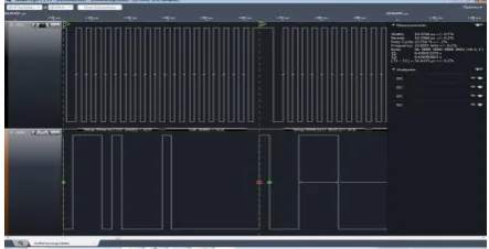
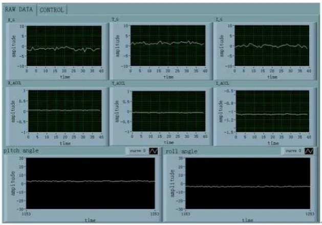
The I2C lines are initialized with the required mode, duty cycle, clock speed etc. To ensure that the communication is happening with the required slave device the chip id or the device id of the slave is checked. The 9DOF-IMU sensor used has a register called WHO_AM_I to verify the identity of the device. The WHO_AM_I register with address of 0x75 has a value 0x68 stored in it. I2C Communication between Magnetometer and STM32 board captured in logical analyzer is shown in Fig 7.
Fig 8: results obtain by the MPU sensor (Pitch, roll, yaw)
The retrieved data from the BMP is shown in Fig 7.
Fig 7: Retrieved data from BMP
Depending upon these sensor values stored in external flash memory the autopilot controller will generates the PWM (Pulse Width Modulation) signals to control the MAV with required condition.
V.
SYSTEM MERITS
Existing Work
The method of using conventional autopilot controller has a limitation in processing capability and also lags in producing reactive output. Conventional autopilot controller demands large amount of memories and area which lead also to an increase in system cost. The comparison between existing and the proposed system is shown in Table.1.
Proposed Work
The problem of Size, cost and performance can be overcome by using the Free RTOS based STM32 autopilot controller, as it does well in all the domains in which the conventional systems fail.
VI.
CONCLUSION
Purpose Configurable Controller for Indoors and Outdoors GPS-Denied Navigation for Multirotor Unmanned Aerial Vehicles. Journal of Intelligent & Robotic Systems, 2014, 73(1-4), 387-
[5] 400.
[6] Chao, Haiyang, Yongcan Cao, and Yang Quan Chen. "Autopilots for small fixed-wing unmanned air vehicles: A survey." In Mechatronics and Automation, 2007. ICMA 2007. International Conference on, pp. [7] “Design of a Miniature, Multi-Directional Optical Flow Sensor for Micro Aerial Vehicles” Daniel Watman
and Hideaki Murayama, International Conference on Robotics and Automation Shanghai International Conference, 2011, Shanghai, China.
[8] J. Metge, R. Megret, A. Giremus, Y. Berthoumieu,
[9] C. Mazel „Dynamic magnetic field compensation for micro UAV attitude estimation‟ International Conference on Unmanned Aircraft Systems, 2013
[10] Xiangtong Kong, Chunping Wang, Shuying Sun, FeiGao, „A Method of Digital to Shaft-angle Converting Using ARM series MCU&CPLD‟ Fifth International Symposium on Computational Intelligence and Design,2012.
[11] Hines L.L., Arabagi V., Sitti M., „Free flight simulations and pitch and roll control experiments of a sub-gram flapping-flight micro aerial vehicle‟,IEEE International Conference Robotics and Automation, 2011. [12] S. Winkler, M. Buschmann, L. Kruger, H.-W. Schulz, P. Vorsmann, „Multiple Sensor Fusion for
Autonomous Mini and Micro Aerial Vehicle Navigation‟, IEEE-2011.