ORIGINAL ARTICLE DOI 10.1007/s10086-006-0869-1
Chengyuan Li · Nam-Ho Lee
Effect of external compressive load on tangential strain behavior in
Japanese larch log cross sections during radio-frequency/vacuum drying
Abstract This study investigated the effect of a compres-sive load of 0.092 MPa on the history of the tangential strains in Japanese larch (Larix leptolepis Gordon) log cross sections subjected to external compressive load during radio-frequency/vacuum drying. The external compressive load of 0.092 MPa played a role in inducing cracking in the outer zone of the log cross section, combining with other tensile strains. However, it also played a role in reducing the heart checks in the core of log cross section when ex-erted on the cross section of log cross section.
Key words Compressive loading · Radio-frequency/vacu-um drying · Heart check and cracking in log cross section
Introduction
As a form of woody material for the manufacture of arti-facts and high-value items, log cross sections possess some distinctive merits in sawing and natural beauty. However, the drying of log cross sections is much more diffi cult than lumber or timber drying, because checks and cracks are likely to develop. Research has shown that the occurrence of checks and cracks is mainly related to nonuniform
shrink-age stresses.1–4
The drying process of log cross sections subjected to ex-ternal compressive loading during radio-frequency/vacuum (RF/V) drying can be considered as a shrinking process
under both external compressive load and restraint from internal stresses in vacuum. Therefore, a comprehensive understanding of shrinkage behavior is essential to prevent the formation of checks and cracks.
When small wood was subjected to an external constant compressive load during RF/V drying, as in the previous
study,5
the shrinkage of the small wood was signifi cantly increased in the loading direction because of a mechano-sorptive effect, whereas the shrinkage was restrained in the direction perpendicular to the loading direction based on Poisson’s ratio.
The shrinkage of large wood (lumber or timber) during conventional drying is signifi cantly different from that of small wood under constant load in that there are more kinks of stresses inside large wood. Thus, large wood is fully or partly constrained by these stresses during the entire drying process.
The restrained tangential shrinkage and the free tangen-tial shrinkage in log cross sections under conventional dry-ing are considerably different. Moreover, the restrained tangential shrinkage is different at different positions on the
same growth ring (Kato et al. 1978).3
Therefore, it can be inferred that the shrinkage in a log cross section is subjected to complicated stresses, and the stresses may be different in different positions inside the cross section. Because of these factors, the comprehensive effect of these stresses on shrink-age behavior at the different stshrink-ages of drying and at differ-ent radial positions in Japanese larch (Larix leptolepis Gordon) log cross sections is not well understood. Thus, the tangential strain behavior, and its history in the process of shrinking subjected to various kinds of stresses and their interactions are also not clear.
Although some research on tangential strain related to checks and cracks of log cross sections during both
conven-tional drying1–3,6–8
and RF/V drying4,9
have been conducted, few reports can be found on this subject related to compres-sive load during RF/V drying. This study was carried out to investigate the history and distribution of tangential strains in Japanese larch log cross sections subjected to compres-sive load during RF/V drying to provide a theoretical basis for the prevention of checks and cracks.
C. Li (*)
Department of Wood Science and Technology, Beihua University, No.32 Taishan Road, Jilin City, Jilin Province 132013, People’s Republic of China
Tel. 86-432-6965096; Fax 86-432-6965096 e-mail: [email protected]
N.H. Lee
Department of Forest Products, Chonbuk National University, Chonju, Chonbuk 561-756, Republic of Korea
Materials and methods
Preparation of materials
Eight green Japanese larch (Larix leptolepis Gordon) logs with a length of 360 cm and average diameter of 23 cm were obtained from a saw mill. About 30-cm-long log cross sec-tions were cut from both ends of each log, and then two 1-cm-thick log cross sections for measuring initial moisture contents (MC) were prepared from the remainder of each log. Two 3.5-cm-thick log cross sections, one of which was for compressive load testing (L) and the other for load-free testing (C), were sawn off the remaining portion of the log. The total number of specimens amounted to 80 pieces. The log cross sections for control treatment were debarked. The heartwood area of the log cross sections used in our test averaged 84.4%. The diameters of the specimens were 22 cm and the average green MC of the specimens was 42.0%.
External compressive loading and load-free treatment
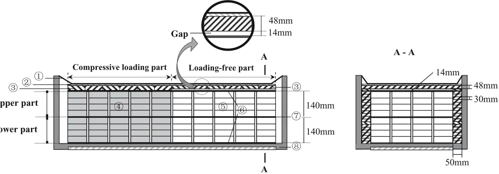
The space inside a vacuum chamber was divided into a compressive loading part and a load-free part (Fig. 1). The log cross sections stacked in the compressive loading part were loaded on their cross sections with a pressure of 0.091– 0.093 MPa when a vacuum pump was turned on or off. The air pressure in the vacuum chamber during RF/V drying was 0.0083–0.0103 MPa. The pressure resulting from the difference in absolute pressure between the inside and the outside of the vacuum chamber was applied to an insulation plate located underneath a 3-mm-thick fl exible rubber sheet covering the vacuum chamber while the chamber was evac-uated. The pressure was transmitted to supporting boards, a top grounded plate, and fi nally to the log cross sections stacked in the compressive loading part (Fig. 1). The top load resulting from the insulation plate, the supporting boards, and the grounded plate was neglected in the loading part.
The log cross sections in the load-free part were kept free from compressive load by the presence of a 14-mm void between the insulation plate and the top grounded plate, even when a vacuum pump was on (Fig. 1). The top load resulting from the insulation plate and the supporting boards was transmitted to the bottom of the chamber in the load-free part.
The log cross sections were solid stacked in eight layers between an electric charge plate and the ground plates in both the compressive loading part and the load-free part. A log cross section with the temperature sensor was posi-tioned in the lower part.
RF/V drying
The inside dimensions of the chamber connected to the RF heater were 102 cm wide, 274 cm long, and 40 cm high. The log cross sections were heated in 10-min cycles by a 7 kW RF generator at a fi xed frequency of about 13 MHz, with the generator being turned on for 8 min and then off for 2 min. The central electrode plate connected to the RF generator was positive, while the top and bottom plates grounded to the chamber itself were negative. The drying temperature of the wood was set from 42° to 53°C, and au-tomatically monitored and controlled by a Tefl on-sheathed platinum sensor inserted into the log cross section.
Measuring tangential strains in log cross sections
To investigate the history of the tangential strains during RF/V drying, a set of two log cross sections (one piece for each treatment) at a time were taken out of the drier at
different stages of drying. Based on literature methods,9–11
a gauge installation position was marked on the outer pe-ripheral surface of each specimen. The position was lightly polished with an abrasive paper (no. 80) and cleaned with compressed air to ensure that the strain gauge was well bonded to the wood. A strain gauge (LFLA-10-11, Tokyo Sokki Kenkyujo, Japan) was peripherally bonded with
30mm 48mm
50mm 14mm
A - A
140mm
140mm
Upper part
Lower part
A
A Compressive loading part Loading-free part
48mm
Gap 14mm
strain gauge adhesive (CN-E, Tokyo Sokki Kenkyujo) on the prepared position. To seal moisture, a waterproof tape (3M Scotch VM) was glued on the strain gauge.
Three holes with diameters of 1, 3, and 5 cm were con-centrically drilled from the center toward the periphery of each specimen, and then the circumferential strips with the inside diameters of 7, 9, 11, 13, 15, 17, 19, and 21 cm were sawn off the remainder of the specimen in the order of the magnitude of the diameter from small to large with a jigsaw (V-3, Tokyo Sokki Kenkyujo).
The scraps from drilling holes and the circumferential strips were oven-dried, and the MCs of the circumferential strips and scraps from each specimen were calculated. Each value of the tangential strain on the outer periphery of the specimen, which was released enough and reached maximum value after a circumferential strip or a hole was cut or drilled, was input into a strain meter (TC-31k, Han Wha Working Machinery, Korea) connected to the strain gauge, and the maximum value was recorded. The recorded value is an accumulated value of the tangential strain of the outer periphery of the specimen, refl ecting a change of the tangential strain of each circumferential strip or scrap with-in a specimen. Therefore, the tangential strawith-in of each cir-cumferential strip or scrap within a specimen was calculated
according to the following formula:12
εt b θ θ
b =(f − ×f) d − + ×
df
f f
f
2 (1)
where et is the tangential strain of a circumferential strip or
scrap within a log cross section (me) unite of strain, fb is the
area of the cross section of a log cross section (cm2
), f is the
area of the circumferential strip or scrap cut off (cm2
), and
q is the tangential strain on the outer periphery of a log
cross section when a circumferential strip or scrap is being
cut (me), that is, the measured tangential strain.
Center Pe riphe ry
Relative location (r/R)
Te
n
si
le
Tan
g
en
ti
al
s
tr
a
in
s
(
me
)
Co
m
p
re
ss
iv
e
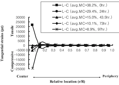
Fig. 2. A history of the tangential strains from the center to the bark of a loaded control (L-C) specimen at different stages of drying. r/R is the relative measure of distance from the pith where r is the radius from the cross section center and R is the radius of the cross section sample
Center Periphery
Relative location (r/R)
Tensile
Ta
ng
ential stra
ins (
me
)
Co
m
p
ressiv
e
Center Periphery
Relative location (r/R)
Tensile
Ta
ng
entia
l stra
ins (
me
)
Co
m
pressive
Center Periphery
Relative location (r/R)
Tensile
Tange
nt
ial s
tr
ains
(
me
)
Compr
es
si
ve
Fig. 5. A history of the tangential strains from r/R = 0.13 to 0.93 r for an NL-C specimen at different stages of drying
Fig. 4. A history of the tangential strains from the center to the bark of a load-free control (NL-C) specimen at different stages of drying Fig. 3. A history of the tangential strains from r/R = 0.14 to 0.94 of an L-C specimen at different stages of drying
Results and discussion
The tangential strain histories with decreasing MC at dif-ferent radial positions in the loaded and load-free control treatment specimens are shown in Figs. 2, 3, 4, and 5.
were in agreement with Kubler’s pattern.2 Kubler’s pattern is the tensile strain in the core and the compressive strain near the bark. However, the patterns in this experiment disagreed with Kubler’s pattern at two points. One was that the zero strain or crossover point was 0.13R (R is the radius of the specimen) from the center of specimen, which was closer to the pith than Kubler’s 0.368R, because Kubler’s model disregarded the Poisson effect of the longitudinal
growth stresses on tangential strain.2 The other is that the
highest tensile strains measured in this experiment are
21 741 me for L-C and 27 336 me for NL-C, which are much
higher than the highest value (12 600 me) found in the
literature.2,13
As drying proceeded, some tendencies were shown quite
clearly. In the zone from the center to r/R = 0.13 (r is the
radius of the slice), the tangential tensile strains for NL-C treatment remained as tensile strains in spite of temporarily being compressive strains when the MCs of the specimens were 18.3%, while the tangential tensile strains for L-C treatment reversed to compressive strains when the MCs of the specimens were 29.4% (Figs. 2 and 4; Table 1).
In the zone toward the bark (r/R = 0.13 to 0.95), the
tangential compressive strains for NL-C treatment reversed to tensile strains and grew to the maximum tensile strains when the MCs of the specimens were 18.3% and then approached zero strain, while the tangential compressive strains for L-C treatment reversed to tensile strains when the MCs of the specimens were 15.0% and then continu-ously increased to the maximum tensile strains at the last stage of drying (Figs. 3 and 5). The values of the tensile strains for L-C treatment were higher than those for NL-C treatment when the MCs of specimens were below 12.1% (Table 1).
Therefore, the possibility of developing heart checks is high for NL-C treatment in the core (from the center to r/R
= 0.13) of the log cross section, while the possibility of
de-veloping cracks is high for L-C treatment in the zone toward the bark when the MCs of specimens are below 12.1%. These tendencies can be a result of the interaction of the various kinds of stresses. When a log is crosscut into log cross sections, the longitudinal growth stresses are released on the very end of the log cross section. This makes the
primary transverse tensile strains near the pith higher be-cause the tangential crosscut strains released from crosscut-ting are also highest near the pith. When an external load of 0.092 MPa is applied on the cross section of the L-C
speci-men, the load expands the specimen laterally.2,6,14
Conse-quently the load reduces the original tangential compressive strains in the zone toward the bark and the tangential ten-sile strains in the core of the log cross section. This effect has a role in inducing cracking in the zone toward the bark, combining with other tensile strains. However, it also has a role in reducing or preventing the heart checks in the core. This also is a main factor that causes differences in the pat-terns of the strain distribution for the loaded and load-free specimens (Figs. 2–5).
During the early stage of drying, the vapor pressure gradients from the inside to the outside of the wood (rapid vapor generation inside wood produces signifi cant total pressure gradients in addition to partial vapor pressure
gra-dients),15,16
and the hygrothermal recoveries up to the fi ber saturation point (FSP) also generate additional tangential tensile strains. These cause the tangential compressive strains in the zone toward the bark to be further reduced and approach tensile strain. When the MCs of specimens are decreased below the FSP, the nonuniform shrinkage strains in the control treatment occur and neutralize the tangential tensile strains in the core and the tangential com-pressive strains near the bark to some extent because of their pattern of transverse tension near the bark and
trans-verse compression in the core.7 Ultimately, these strains
make the tangential compressive strains in the zone toward the bark approach the tangential tensile strains.
As drying proceeds further, the tangential tensile strains in L-C treatment specimens become larger because the di-rection of the tensile strains is in the opposite didi-rection of tangential shrinkage and the larger tensile strains increas-ingly restrain the tangential shrinkages. When these tensile strains are large enough, if the tensile stresses cannot be suffi ciently relaxed, cracking inevitably occurs. When the tangential tensile strains in NL-C treatment specimens ap-proach zero after reaching a certain level of tensile strains because the tangential shrinkages in NL-C treatment speci-mens are less restrained by tensile strains.
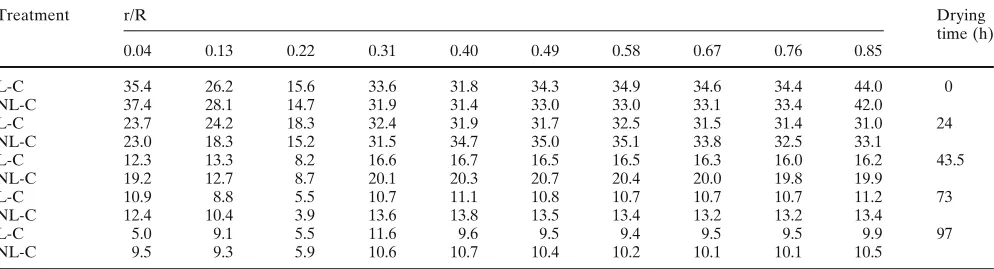
Table 1. Moisture contents of two treatment specimens during drying in relation to distance from cross section center
Treatment r/R Drying
0.04 0.13 0.22 0.31 0.40 0.49 0.58 0.67 0.76 0.85 time (h)
L-C 35.4 26.2 15.6 33.6 31.8 34.3 34.9 34.6 34.4 44.0 0
NL-C 37.4 28.1 14.7 31.9 31.4 33.0 33.0 33.1 33.4 42.0
L-C 23.7 24.2 18.3 32.4 31.9 31.7 32.5 31.5 31.4 31.0 24
NL-C 23.0 18.3 15.2 31.5 34.7 35.0 35.1 33.8 32.5 33.1
L-C 12.3 13.3 8.2 16.6 16.7 16.5 16.5 16.3 16.0 16.2 43.5
NL-C 19.2 12.7 8.7 20.1 20.3 20.7 20.4 20.0 19.8 19.9
L-C 10.9 8.8 5.5 10.7 11.1 10.8 10.7 10.7 10.7 11.2 73
NL-C 12.4 10.4 3.9 13.6 13.8 13.5 13.4 13.2 13.2 13.4
L-C 5.0 9.1 5.5 11.6 9.6 9.5 9.4 9.5 9.5 9.9 97
NL-C 9.5 9.3 5.9 10.6 10.7 10.4 10.2 10.1 10.1 10.5
Moisture content data given as percentages
Conclusions
This study investigated the effect of a compressive load of 0.092 MPa on the history of tangential strains in the Japa-nese larch log cross sections subjected to external compres-sive load during RF/V drying. In the core of the log cross section, the tangential tensile strains for NL-C remained as tensile strain, while the tangential tensile strains for L-C treatment reversed to compressive strain.
In the zone toward the bark, the tangential compressive strain for NL-C treatment reversed to tensile strain and then approached to zero, while the tangential compressive strain for L-C treatment reversed to tensile strain and then increased to the maximum value at the last stage of drying. The values of the tensile strains for L-C treatment were higher than those for NL-C treatment when the MCs of the specimens were below 12.1%. Therefore, the possibility of developing heart checks in the core is high for NL-C treat-ments, and the possibility of developing the cracks in the zone toward the bark is high for L-C treatment when the MCs of specimens are below 12.1%.
A compressive load of 0.092 MPa has a role in inducing cracking in the zone toward the bark, combining with other tensile strains. However, it also has a role in reducing heart checks in the core when it is exerted on the cross section of log cross section.
References
1. Kubler H (1974) Drying tree disks simply and without defects. Forest Prod J 24:33–35
2. Kubler H (1987) Growth stresses in trees and related wood proper-ties. Forest Prod Abst 10:74–107
3. Kato H, Sadoh T, Matsui K, Kondo K, Nakato K (1978) Shrinkage and crack formation of cross-sectional tree-disks. Bull Kyoto Univ For 50:191–197
4. Lee NH, Hayashi K, Jung HS (1998) Effect of radio-frequency/ vacuum drying and mechanical press-drying on shrinkage and checking of walnut log cross sections. Forest Prod J 48:73–79 5. Li C, Lee NH (2004) Effect of compressive load on shrinkage of
larch blocks under radio-frequency/vacuum heating. Wood Fiber Sci 36:9–16
6. Hsu NN, Tang RC (1974) Internal stresses in wood logs due to anisotropic shrinkage. Wood Sci 7:48–49
7. Kubler H (1975) Study on drying of tree cross sections. Wood Sci 7:173–181
8. Kubler H (1977) Formation of checks in tree stems during drying. Forest Prod J 27:41–46
9. Kawabe J, Sakamoto K, Fujimoto N, Mataki Y (1993) Vacuum-drying with high-frequency Vacuum-drying of sugi logs. Mokuzai Gakkaishi 39:284–292
10. Okuyama T, Sasaki Y (1978) The residual stresses in wood logs due to growth stresses. IV. The growth stresses piled in the trunk. J Jpn Wood Res Soc 24:77–84
11. Sasaki Y, Okuyama T, Kikata Y (1981) Determination of the re-sidual stress in a cylinder of inhomogeneous anisotropic material. II. J Jpn Wood Res Soc 27:277–282
12. Mataki Y, Kawabe J (1988) Vacuum drying of Japanese cedar with radio frequency heating – the effect of the changes of internal stress and the transpirational drying. Research Report of Labora-tory of Wood Technology, Department of Forest Products, Faculty of Agriculture, Kyushu University, p 12
13. Youngs RL (1957) Mechanical properties of red oak related to drying. Forest Prod J 7:315–324
14. Burgert I, Okuyama T, Yamamoto H (2003) Generation of radial growth stresses in the big rays of konara oak trees. J Wood Sci 49: 131–134
15. Wanananen K, Okos MR (1989) Analysis of mass transfer mecha-nisms during drying of extruded semolina. Proceedings of the 5th International Congress on Engineering and Food, Cologne, Germany, pp 154–159