404 |
P a g e
INFLUENCE OF DIFFERENT PARAMETERS TOWARDS
MILLING BURR MINIMIZATION AT WET CONDITION
S.K.Singh
1, S.R.Dutta
21,2
Assistant Professor Department of ME, West Bengal University of Technology, India
ABSTRACT
Undesirable burrs are created in most of the machining processes. A burr is a plastically deformed material that remains attached at the workpiece edges after machining, and must be removed for making the parts to function effectively. The main objective of the present work is to explore the suitable condition to obtain minimum or negligible burr around the edge of a machined product at wet condition.In this work, experiments have been carried out on a vertical axis CNC milling machine to perform face milling on aluminium alloy (Alloy-4600M) blocks with single inserted coated carbide tool on a 54 mm diameter cutter for observing the nature of burr formation.
Keyword
:
Aluminium alloy, Burr, Carbide Tool, CNC Milling Machine, Wet conditionI. INTRODUCTION
A burr is a plastically deformed material that remains attached at the workpiece edges after machining. It is
often in the form of a rough strip of metal present at the edge of the workpiece adjacent to the machined surface.
Burrs must be removed for making the parts to function effectively [1]. Material removal by milling process is
considered as one of the most multipurpose and extensively used machining processes. Burrs generated in
workpiece produced by milling operation is a serious concern because the presence of burr on the cutting edges
could significantly affect the cutting performance. A clear understanding of burr formation mechanism would be
of great importance in minimizing burr, and hence, would improve manufacture of precision jobs. Silva et al. [2]
investigated the burr formation mechanisms at the edges (lateral and exit) during face milling of mould steel
using carbide tools. They proposed that burrs were minimised by optimizing the cutting conditions like cutting
speed (Vc), feet per tooth (fz) and depth of cut (doc).
Chern [1] experimentally found the different types of burr formed, which is highly dependent on the in-plane
exit angle, ψ. Five types of burrs were created and observed in the experiments, they are knife-type burr,
wave-type burr, curl-wave-type burr, edge breakout burr, and secondary burr. Shefelbine and Dornfeld [3] stated that in case
of dry machining, burr formation was larger because of increased ductility at elevated temperatures. But, Heisel
et al. [4] experimentally found with the reference material C45E as well as some comparative materials that the
influence of minimum quantity lubrication on burr formation in face milling. The burr value increased in
machining with minimum quantity lubrication compared to dry machining.
A study carried out [5] in the German automotive and machine tool industries showed costs associated with
burr minimization, deburring and part cleaning. To evaluate the economic impact of expenses caused by burrs,
405 |
P a g e
Expenses were caused by an increase of about 15% in man power and cycle times. In addition, 2% share in the
reject rate and 4% share in machine breakdown times due to burrs, were reported. Control and removal of burrs
are one of the important issues in many machining operations and have been in the focus of research in cutting
operations for the last 50 years.
The main objective of the present work is to explore suitable machining condition to obtain minimum or
negligible burr formation on a machined product at wet condition, using water soluble Blasocut Combi as
cutting fluid. Observation on influence of different cutting velocities (Vc), feeds (So), and in-plane exit angles
(ψ) on the burr formation in face milling of aluminium alloy with 0˚ and 15˚ exit edge bevel angel, keeping
depth of cut (t) constant for all machining conditions and observed the burr formation mechanism.
II. EXPERIMENAL PROCEDURE
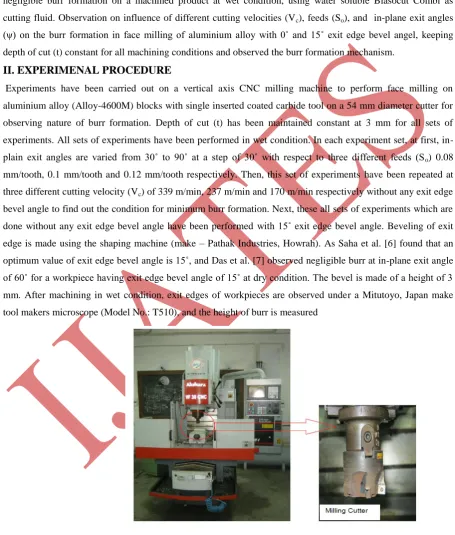
Experiments have been carried out on a vertical axis CNC milling machine to perform face milling on
aluminium alloy (Alloy-4600M) blocks with single inserted coated carbide tool on a 54 mm diameter cutter for
observing nature of burr formation. Depth of cut (t) has been maintained constant at 3 mm for all sets of
experiments. All sets of experiments have been performed in wet condition. In each experiment set, at first,
in-plain exit angles are varied from 30˚ to 90˚ at a step of 30˚ with respect to three different feeds (So) 0.08
mm/tooth, 0.1 mm/tooth and 0.12 mm/tooth respectively. Then, this set of experiments have been repeated at
three different cutting velocity (Vc) of 339 m/min, 237 m/min and 170 m/min respectively without any exit edge
bevel angle to find out the condition for minimum burr formation. Next, these all sets of experiments which are
done without any exit edge bevel angle have been performed with 15˚ exit edge bevel angle. Beveling of exit
edge is made using the shaping machine (make – Pathak Industries, Howrah). As Saha et al. [6] found that an
optimum value of exit edge bevel angle is 15˚, and Das et al. [7] observed negligible burr at in-plane exit angle
of 60˚ for a workpiece having exit edge bevel angle of 15˚ at dry condition. The bevel is made of a height of 3
mm. After machining in wet condition, exit edges of workpieces are observed under a Mitutoyo, Japan make
tool makers microscope (Model No.: T510), and the height of burr is measured
406 |
P a g e
Table 2.1: Experimental Details
Machine Tools Vertical Axis CNC Milling Machine.
Make: Bharat Fritz Werner, India. Type: Akshara VF30CNC, Sl. No.:
5081/269.
Cutting Tool TiN Coated Carbide Insert for Face Milling (Single Insert).
Cutter Diameter: 54mm.
Make: Sandvik Asia Ltd., India.
Cutter Specification: 490-054Q22-08M241259
Insert Specification: 490R-08T308M-PM
Job Material Aluminum Alloy (Alloy 4600M)
Hardness: 30 HRA.
Composition: Cu (0.1%), Si (12.0%), Mg (0.1%), Mn (0.5%), Ni (0.1%), Zn
(0.1%), Pb (0.1%), Sn (0.1%), Ti (0.1%), Fe (0.1%) and Al (remaining).
Size: 79mm × 72mm × 46mm.
In-plain exit angle (˚) 30, 60, 90
Exit edge bevel angle (˚) 0 &15
Cutting velocity (Vc)
(m/min)
339
Feed (So) (mm/tooth) 0.08, 0.1, 0.12
Depth of cut (t) (mm) 3
Environment Wet (Cutting Oil:Blasocut Combi ,Make: Blaser Swisslube, Swetzerland.)
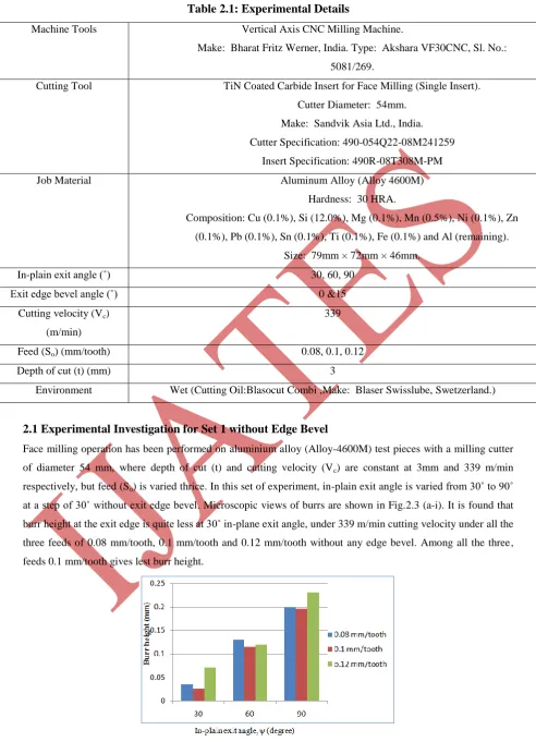
2.1 Experimental Investigation for Set 1 without Edge Bevel
Face milling operation has been performed on aluminium alloy (Alloy-4600M) test pieces with a milling cutter
of diameter 54 mm, where depth of cut (t) and cutting velocity (Vc) are constant at 3mm and 339 m/min
respectively, but feed (So) is varied thrice. In this set of experiment, in-plain exit angle is varied from 30˚ to 90˚
at a step of 30˚ without exit edge bevel. Microscopic views of burrs are shown in Fig.2.3 (a-i). It is found that burr height at the exit edge is quite less at 30˚ in-plane exit angle, under 339 m/min cutting velocity under all the three feeds of 0.08 mm/tooth, 0.1 mm/tooth and 0.12 mm/tooth without any edge bevel. Among all the three,
407 |
P a g e
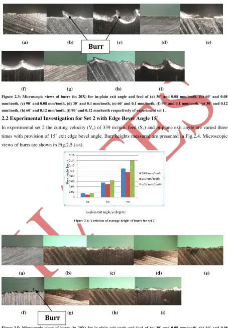
Figure 2.3: Microscopic views of burrs (in 20X) for in-plain exit angle and feed of (a) 30˚ and 0.08 mm/tooth, (b) 60˚ and 0.08 mm/tooth, (c) 90˚ and 0.08 mm/tooth, (d) 30˚ and 0.1 mm/tooth, (e) 60˚ and 0.1 mm/tooth, (f) 90˚ and 0.1 mm/tooth, (g) 30˚ and 0.12 mm/tooth, (h) 60˚ and 0.12 mm/tooth, (i) 90˚ and 0.12 mm/tooth respectively of experiment set 1.
2.2 Experimental Investigation for Set 2 with Edge Bevel Angle 15˚
In experimental set 2 the cutting velocity (Vc) of 339 m/min, feed (So) and in-plane exit angle are varied three
times with provision of 15˚ exit edge bevel angle. Burr heights measured are presented in Fig.2.4. Microscopic
views of burrs are shown in Fig.2.5 (a-i).
Figure.2.5: Microscopic views of burrs (in 20X) for in-plain exit angle and feed of (a) 30˚ and 0.08 mm/tooth, (b) 60˚ and 0.08 mm/tooth, (c) 90˚ and 0.08 mm/tooth, (d) 30˚ and 0.1 mm/tooth, (e) 60˚ and 0.1 mm/tooth, (f) 90˚ and 0.1 mm/tooth, (g) 30˚ and 0.12 mm/tooth, (h) 60˚ and 0.12 mm/tooth, (i) 90˚ and 0.12 mm/tooth respectively of experiment set 2.
Burr
(a) (b) (c) (d) (e)
(g)
(e)
(f) (h)
(e)
(i)
(e)
(a) (b) (c) (d) (e)
(f) (g) (h) (i)
408 |
P a g e
III. CONCLUSION
On the basis of the experimental investigation in face milling carried out in this work, following conclusions
may be drawn.
1. Among the three in-plane exit angle (ψ) undertaken, in-plane exit angle of 30˚ gives quite less burr
formation with the exit edge bevel angle, of 0˚and 15˚ at wet environment using TiN coated carbide
tool under all speed-feed condition.
2. At the medium feed (So) condition of 0.1 mm/tooth and high cutting velocity (Vc) of 339 m/min,
observed burr height at an in-plane exit angle of 30˚ for a workpiece having exit edge bevel angle of
15˚ is the lowest in this experimental work, and may be considered negligible. At a low in-plane exit
angle, the need of backup support material is less, and therefore, the chance of burr formation becomes
negligible. Low exit edge bevel also reduces requirement of backup support, due to gradual decrease in
depth of cut. So, for this reason, burr formation is negligible at low in-plane exit angle, and at
somewhat low exit edge bevel angle.
REFERENCES
[1] G.L. Chern, 2006, ‘Experimental Observation and Analysis of Burr Formation Mechanisms in
Face Milling of Aluminium Alloys’, International Journal of Machine Tools & Manufacture, Vol. 46, pp. 1517–1525.
[2] J.D. Silva, F.P. Saramango, A.R. Machado, 2009, ‘Optimization of the Cutting Conditions
for Burr Minimization in Face Milling of Mould Steel’, Journal of the Braz. Soc. Of Mech. Sci. and Eng., Vol. XXXI, No. 2, pp. 151-160.
[3] W. Shefelbine, D Dornfeld, 2004, ‘The Effect of Dry Machining on Burr Size’, Laboratory for
Manufacturing and Sustainability, pp. 1-5.
[4] S. Heisel, M. Schaal, G. Wolf, 2009, ‘Burr Formation in Milling with Minimum Quantity
Lubrication’, German Academic Society for Production Engineering, Vol. 3, No. 1, pp. 23-30.
[5] J.C. Aurich, D. Dornfeld, P.J. Arrazola, V. Franke, L. Leitz, S. Min, 2009, ‘Burrs—Analysis,
Control and Removal’, CIRP Annals - Manufacturing Technology, Vol.58, pp. 519–542.
[6] S.P Pratim and S. Das, 2011, ‘Burr Minimization in Face Milling: an Edge Bevelling Approach’,
J. Engineering Manufacturing, Vol. 225, Part B, pp. 1528-1534.
[7] P.P. Saha, D. Das, and S. Das, 2007, ‘Effect of Edge Beveling on Burr Formation in Face Milling’,