Compact Four-Element MIMO Antenna System Based on
Substrate-Integrated-Waveguide Cavities
Bing-Jian Niu* and Jie-Hong Tan
Abstract—A compact four-element multiple-input-and-multiple-output (MIMO) antenna system is proposed based on substrate-integrated-waveguide (SIW) cavities. By bisecting a square SIW cavity, two rectangle half-mode cavities with opened edges are formed. They are arranged side by side sharing a row of metallic vias. Then two narrow T-shaped slots are etched along symmetry planes to divide these two cavities into four quarter-mode sub-cavities. Excited by feeding ports, four antenna elements with compact size are constructed, which radiate incident wave through opened cavity edges and etched slots. Moreover, antenna isolation can be easily improved by adjusting slot length though these elements interconnect. A prototype with the cavity size of 0.22λ0 ×0.86λ0 ×0.04λ0 has been fabricated. The
fabricated MIMO antenna system exhibits the center frequency of 3.51 GHz, port isolation of 14 dB, envelope correlation coefficient of 0.03, peak gain of 4.9 dBi, and high efficiency of 77.4%. The compact size and effective isolation improvement make the proposed design attractive for practical applications.
1. INTRODUCTION
With further requirements of high data rate and reliable link quality, multiple-input-and-multiple-output (MIMO) technology has been greatly introduced in modern wireless communication. As an important part, massive antenna elements are utilized to exploit multipath environments and provide multiplexing/diversity channel gain [1–3]. However, this generally leads to large overall size and poor isolation. Therefore, multiple-element MIMO antenna systems with compact size and high isolation are mostly required.
In recent years, substrate-integrated-waveguide (SIW) cavities have been widely studied for antenna designs, due to attractive advantages such as low profile, low-cost fabrication, and seamlessly planar integration [4–6]. However, these antennas have a drawback of large cavity size. Half-mode (HM) and quarter-mode (QM) cavity antennas are investigated in [7–10]. Though compact size is obtained, only an antenna element can be formed in these SIW cavities. A two-element MIMO antenna system based on SIW technology has been developed in [11], in which high isolation is achieved by increasing antenna distance and optimizing system configuration. Recently, four-element MIMO systems have been reported in [12, 13] where isolating elements are utilized to reduce the coupling among antenna elements. However, these designs suffer from complex structures and low radiation efficiency which limit their practical applications.
In this letter, a compact four-element MIMO antenna system based on SIW cavities is proposed. In order to achieve compact size, antenna elements are constructed in QM sub-cavities which are connected with each other. The isolation among them can be effectively improved by adjusting the length of two etched T-shaped slots. The design evolution, parametric study, field distribution, and 3-D radiation pattern are given. Experimental results of a fabricated prototype demonstrate a decent agreement with the simulation ones.
Received 27 October 2019, Accepted 20 December 2019, Scheduled 8 January 2020
* Corresponding author: Bing-Jian Niu ([email protected]).
2. GEOMETRY AND DESIGN
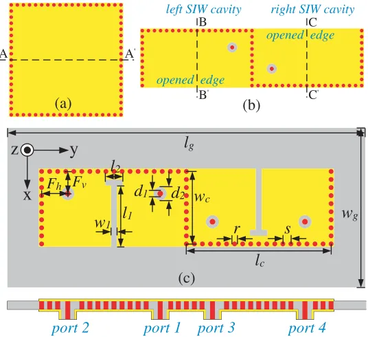
The geometrical evolution of the proposed design is shown in Figure 1. Enclosed by metallic vias with diameterrand center-to-center spacings, a square SIW cavity is printed on a single layer substrate with the permittivity εr= 2.5 and thicknessh= 3 mm. By bisecting it along the symmetry plane A-A, two rectangle HM cavities are formed. Compared to the former with a closed structure, the latter possesses opened edges which can effectively radiate cavity energy into free space. Then they are arranged side by side to obtain radiation diversity, and a row of vias are shared to achieve compact size. Excited by coaxial ports, a two-element MIMO antenna system is realized. Note that the inner probes and outer conductors of ports are connected with the top and bottom planes of SIW cavities, respectively. Proper antenna matching can be obtained by optimizing port positions (Fv and Fh).
r
s
x
z
y
l
gFv Fh
port 2
l
cw
gport 1 port 3 port 4
l
1w
1l
2w
cA A'
B
B'
C
C'
left SIW cavity right SIW cavity
(a) (b)
(c)
opened edge
opened edge
d
1d
2Figure 1. Geometrical evolution: (a) square SIW cavity; (b) two-element MIMO antenna system; and (c) four-element MIMO antenna system.
In order to further increase the quantity of antenna elements, a narrow T-shaped slot is etched alongB-B andC-C, respectively. As shown in Figure 1(c), it consists of a long slot stubl1 and a short
stub l2 with the same width w1. It should be noted that etched slots can not only divide these HM
cavities into four QM sub-cavities and but also reduce the energy coupling among them. The effects of these slots on port isolation are shown in Figure 2. When slots are removed, S21is as high as −3.1 dB.
As slot lengthl1gradually increases, port isolation between elements 1 and 2 is greatly improved within
the frequency of interest while S31 keeps high isolation almost unchanged. This simple and effective
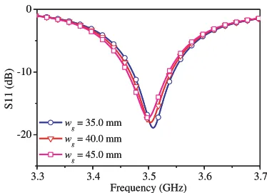
isolation improvement makes the proposed design attractive for practical applications. Moreover, as shown in Figure 3, the reflection coefficientS11 is hardly affected by the ground plane. This is because
cavity resonances are utilized in the proposed design, which are primarily determined by cavity size (lc and wc). Therefore, a four-element MIMO antenna system with compact size and high isolation is proposed.
3.3 3.4 3.5 3.6 3.7 -30
-20 -10 0
3.3 3.4 3.5 3.6 3.7 -30
-20 -10 0
operating band without slot
l
1 = 13.0 mm l1 = 13.5 mm
l
1 = 14.0 mm
operating band
S21 (dB)
Frequency (GHz)
without slot
l1 = 13.0 mm
l
1 = 13.5 mm l
1 = 14.0 mm
S31 (dB)
Frequency (GHz)
Figure 2. Effects of slot length on port isolation.
3.3 3.4 3.5 3.6 3.7
-20 -10 0
wg = 35.0 mm
wg = 40.0 mm
wg = 45.0 mm
S11 (dB)
Frequency (GHz)
3.3 3.4 3.5 3.6 3.7
-20 -10 0
wg = 35.0 mm
wg = 40.0 mm
wg = 45.0 mm
S11 (dB)
Frequency (GHz)
Figure 3. Effects of ground plane on reflection coefficient.
Port 2 is excited Port 1 is excited
Port 3 is excited Port 4 is excited
Figure 4. Simulated electric-field magnitude distribution.
Port 3 is excited Port 1 is excited
Figure 5. Top and side views of simulated 3-D radiation patterns.
elements. This indicates that high isolation has been achieved. The 3-D radiation patterns of elements 1 and 3 are shown in Figure 5. It can be seen that tilted and unidirectional radiation is obtained owing to the reflection effect of metallic vias. Therefore, angle diversity is confirmed in the proposed design. Detailed geometrical parameters optimized by CST Microwave Studio arelg = 90.0 mm,wg= 45.0 mm,
3. EXPERIMENTAL RESULTS
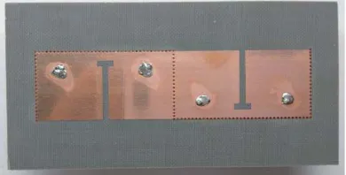
To verify the proposed design, a prototype is fabricated, and 50 Ω SMA connectors are soldered. Figure 6 shows a photo of the fabricated prototype with the cavity size of 0.22λ0 ×0.86λ0 ×0.04λ0. The S
-parameters and radiation performance have been experimented by an Agilent vector network analyzer and a Satimo microwave chamber, respectively.
Figure 6. Photo of the fabricated prototype.
The measuredS-parameters (color curves) are shown in Figure 7, compared with the simulated ones (grey curves). They are in a decent agreement. Since the reflection coefficients (S11,S22,S33, and S44)
differ marginally, only S11 is given. The fabricated antenna operates at 3.51 GHz with impedance
matching of −15.4 dB. The measured 10-dB bandwidth is 65 MHz, which is slightly less than the simulated value of 75 MHz. Moreover, both the simulated and measured port isolations includingS21, S31, and S41 are below 14.0 dB, which is suitable for MIMO operations.
3.3 3.4 3.5 3.6 3.7
-40 -30 -20 -10 0
S11 S21 S31 S41
S-parameters (dB)
Frequency (GHz)
Figure 7. Measured S-parameters compared
with simulated results.
3.40 3.45 3.50 3.55 3.60
0 2 4 6
simulated gain measured gain simulated efficiency measured efficiency
Radiation gain (dBi)
Frequency (GHz)
0 20 40 60 80
Radiation efficiency (%)
Figure 8. Measured radiation gain and efficiency compared with simulated results.
The simulated and measured antenna gains are shown in Figure 8. Because of the symmetry of the MIMO antenna system, only the result of element 1 is given. The measured peak gain is 4.9 dBi, which is slightly lower than the simulated value about 0.2 dBi. Radiation efficiency has been calculated by measuring total radiation power with the angular sampling interval of 2 deg. Measured maximum efficiency is 77.4%.
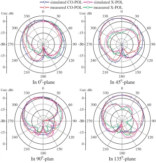
In 00-plane
Unit: dBi Unit: dBi
simulated CO-POL simulated X-POL measured CO-POL measured X-POL
-30 -15 0 0 30 60 90 120 150 180 210 240 270 300 330 -30 -15 0 -30 -15 0 0 30 60 90 120 150 180 210 240 270 300 330 -30 -15 0 -30 -15 0 0 30 60 90 120 150 180 210 240 270 300 330 -30 -15 0 -30 -15 0 0 30 60 90 120 150 180 210 240 270 300 330 -30 -15 0
In 450-plane
In 900-plan In 1350-plane Unit: dBi Unit: dBi
Figure 9. Measured radiation patterns compared with simulated results.
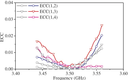
curves) and measured (color curves) ECCs of the proposed design are below 0.03, which is fairly good for MIMO applications.
The performance of the proposed design is summarized in Table 1. Compared with reported works, the proposed four-element MIMO antenna system has advantages of compact size, low profile, high radiation gain, and low ECCs. Therefore, it is a good candidate for 3.5 GHz-band fifth-generation communication [15].
Table 1. Comparison of the proposed design with reported works.
Size (λ0)
Antenna quantity Frequency (GHz) Isolation (dB) Gain (dBi) ECC [1] 0.58×0.72×0.01 2 2.4 20 - 0.005 [4] 0.81×1.45×0.02 1 5.8 - 3.12
-[11] 0.34×0.61×0.02 2 2.4 18 2.9 0.5
5.5 35 5.0
[12] 1.20×1.20×0.11 4 2.4 36 7.1 0.005
[13] 0.41×0.41×0.04 4 3.5 18.4 2.7 0.08
5.7 22.7 2.85
3.40 3.45 3.50 3.55 3.60 0.00
0.01 0.02 0.03 0.04
ECC(1,2) ECC(1,3) ECC(1,4)
ECC
Frequency (GHz)
Figure 10. Measured ECCs compared with simulated results.
4. CONCLUSION
A compact four-element MIMO antenna system is presented. It consists of SIW cavities, etched T-shaped slots, and feeding ports. In order to realize compact antenna elements, four QM sub-cavities are constructed. Moreover, the isolation among them is improved by optimizing slot length. The simulated results of the proposed design includingS-parameters, radiation performance, and MIMO performance are in a decent agreement with the measured results of a fabricated prototype.
REFERENCES
1. Wang, Z., L. Zhao, A. Chen, and Y.-Z. Yin, “A second order decoupling design using a resonator and an interdigital capacitor for a MIMO antenna pair,” Progress In Electromagnetics Research Letters, Vol. 67, 19–24, 2017.
2. Sun, L., H. Feng, Y. Li, and Z. Zhang, “Compact 5G MIMO mobile phone antennas with tightly arranged orthogonal-mode pairs,” IEEE Transactions on Antennas and Propagation, Vol. 66, No. 11, 6364–6369, 2018.
3. Niu, B. and J. Tan, “Compact four-element MIMO antenna using T-shaped and anti-symmetric U-shaped slotted SIW cavities,” Electronics Letters, Vol. 55, No. 19, 1031–1032, 2019.
4. Hong, Y., J. Tak, and J. Choi, “An all-textile SIW cavity-backed circular ring-slot antenna for WBAN applications,”IEEE Antennas and Wireless Propagation Letters, Vol. 15, 1995–1999, 2016. 5. Sboui, F., J. Machac, and A. Gharsallah, “Tunable slot antenna backed by substrate integrated waveguide cavity,” International Journal of RF and Microwave Computer-Aided Engineering, e21591, 2018.
6. Niu, B. and J. Tan, “Compact two-element MIMO antenna based on half-mode SIW cavity with high isolation,” Progress In Electromagnetics Research Letters, Vol. 85, 145–149, 2019.
7. Liu, F., Z. Xu, D. Ranasinghe, and C. Fumeaux, “Textile folded half-mode substrate-integrated cavity antenna,” IEEE Antennas and Wireless Propagation Letters, Vol. 15, 1693–1697, 2016. 8. Tian, H. and T. Itoh, “Development of a circularly polarized HMSIW antenna,” Progress In
Electromagnetics Research Letters, Vol. 87, 81–87, 2019.
9. Deckmyn, T., S. Agneessens, A. Reniers, et al., “A novel 60 GHz wideband coupled half-mode/quarter-mode substrate integrated waveguide antenna,” IEEE Transactions on Antennas and Propagation, Vol. 65, No. 12, 6915–6926, 2017.
10. Casula, G. A., “A quarter mode SIW antenna for short-range wireless communications,” Journal of Electromagnetic Waves and Applications, Vol. 33, No. 7, 853–864, 2019.
12. Zhai, G., Z. N. Chen, and X. Qing, “Mutual coupling reduction of a closely spaced four-element MIMO antenna system using discrete mushrooms,”IEEE Transactions on Microwave Theory and Techniques, Vol. 64, No. 10, 3060–3067, 2016.
13. Boukarkar, A., X. Q. Lin, Y. Jiang, et al., “A miniaturized extremely close-spaced four-element dual-band MIMO antenna system with polarization and pattern diversity,” IEEE Antennas and Wireless Propagation Letters, Vol. 17, No. 1, 134–137, 2018.
14. Sharawi, M. S., A. T. Hassan, and M. U. Khan, “Correlation coefficient calculations for MIMO antenna systems: A comparative study,” International Journal of Microwave and Wireless Technologies, Vol. 9, No. 10, 1991–2004, 2017.