doi: 10.11648/j.ijass.20140201.11
Stereo vision-based relative navigation algorithm for
satellites formation flying
Xiaokui Yue
1, *, Haifeng Su
1, 2, Jianping Yuan
11National Key Laboratory of Aerospace Flight Dynamics, Northwestern Polytechnical University, Xi'an, P. R. China 2Institute of Flight Mechanics and Control, Universität Stuttgart, Germany
Email address:
[email protected] (Xiaokui Yue)
To cite this article:
Xiaokui Yue, Haifeng Su, Jianping Yuan. Stereo Vision-Based Relative Navigation Algorithm for Satellites Formation Flying. International Journal of Astrophysics and Space Science. Vol. 2, No. 1, 2014, pp. 1-5. doi: 10.11648/j.ijass.20140201.11
Abstract:
Space mission with multiple spacecraft formation is an important means to space operation. A new relative navigation algorithm based on stereo vision is developed aiming at high navigation precision requirement of spacecraft formation flying. It uses stereo vision camera attached on the tracking craft as measurement sensor, gets the relative location of target craft in the tracking craft body reference frame with imaging parallax. Relative motion equation is built in inertial frame, and discretized as the state equation of the system. Measurement information of stereo vision is used as measurement value, and the two-step filter relative navigation algorithm based on Kalman filter is designed to estimate relative navigation state in real time, and finally validated by simulation. The simulation results prove this algorithm can meet the relative navigation precision requirements of formation flying.Keywords:
Formation Flying, Stereo Vision, Relative Navigation, Two-Step Filter1. Introduction
Formation satellites are termed as several mini satellites form certain flying contrail, and each mini satellite of the distributed satellite constellation works coordinately to accomplish the mission that a single satellite hardly to obtain. Relative navigation is the precondition of spacecraft rendezvous, accompany and formation flying, especially in short range spacecraft formation flying mission, precision of which will directly affect the precision of navigation and control[1, 2, 3]. Several measure methods frequently are used in Space rendezvous and docking, including: micro-wave rendezvous radar, laser radar, satellite navigation and CCD optical imaging. Vision-based navigation of CCD optical imaging is a highly intelligentized navigation technology widely used in approaching and docking phases of space rendezvous and docking, which is small in volume, light in mass and low in energy consuming[4].
Stereo vision based relative state estimate scheme is addressed in this paper, which estimates the state of target spacecraft relative to the initial one with stereo vision. First, with spacecraft relative motion equation referring to the inertial frame, stereo vision measurement information as measurement equation, simplified stereo vision measurement
error model is built. Second, measurement noise was corrected in real time, and estimate relative position and speed using two-step filter algorithm based on Kalman filter. In the end, numerical simulation as well as validation of this navigation algorithm is made[5-7].
The use of vision system as the navigation and tracking sensor of space assets has become more and more attractive since it is a very efficient choice due to its compact size, low cost and rich information which provides. The nonlinear estimation framework for vision-based target measurement is addressed within this paper where space robot manipulation is considered as reference scenario. The work presented deals with the measurement of relative state parameter of the target including kinematic and dynamic parameters and its size from stereo vision, since the state vector is the basis for navigation and control in formation flying[8, 9].
2. Principles of Binocular Stereo Vision
Measurement and Error Model
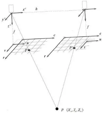
Parallel stereo vision model is the usually binocular stereo vision measurement model. Specifically, when the two cameras of the model are located parallelly, it is termed as standard vision model, illustrated in Fig.1. Assume coordination of the camera on both side are
O x y z
l cl cl cl andr cr cr cr
O x y z
, each origin of the camera frameO
l,O
risthe optical center of the camera, axis
x
c connecting theoptical center, pointing to right camera, distance between two is b, termed as datum line, axis
z
c is the light beam of the camera, axisy
c vertical to flatx z
c c.Assume coordinates of point P in left camera frame is (Xw,Y Zw, w), d =(ul −ur) is defined as binocular parallax
of point P. If the parameter of the camera and parallax d is obtained, the coordinates of point P X( w,Y Zw, w) are:
Fig 1. Principle of binocular stereo vision measurement
0 0 ( ) ( ) ( ) l w l r l l w
r l r
l w
l r
b u u
X
u u
bf v v
Y
f v v
bf Z u u − = − − = − = − (1)
Where: u0, v0, fl, and fr are camera parameters, b
is base line distance.
It is the key step demarcating camera and corresponding points matching, whose precision is the major factor of binocular stereo measurement. Stereo vision measurement error and precision of demarcating and matching are given by reference[8]:
2
2
( )
( ) 2
z z f
z
fb z f z zf zf
δ
δ ε δ
∆ −
∆ =
− + ∆ − ∆ − ∆ (2)
Where: ∆δ is the matching error of the two images,
ε
∆ is demarcating error. For the dimension of both ∆δ and ∆ε is µm, much less than measurement distance z, the measurement error model can be simplified as follow:
2 z z fb δ ∆
∆ = (3)
3. Stereo Vision-Based Relative
Navigation Algorithm for Satellites
Formation Flying
3.1. Spacecraft Relative Dynamic Equation
The relative dynamic equation could be given refer to the geocentric reference frame, as the relative distance of the spacecraft is much less than the distance between spacecraft and the core of earth.
3 2
3 2
3 2
( 3 )
( 3 )
( 3 )
x
y
z
c c c
x c x
c c
c c c
y c y
c c
c c c
z c z
c c
x v
y v
z v
xx yy zz
v x x f
r r
xx yy zz
v y y f
r r
xx yy zz
v z z f
r r µ µ µ = = = + + = − − + + + = − − + + + = − − + ɺ ɺ ɺ ɺ ɺ ɺ (4)
Where µ is G-force constant, x, y,
z
and vx, vy, zv are the location and speed coordinates of target spacecraft refer to initial one in inertial frame, xc, yc, zc
are the location coordinates of the initial spacecraft in inertial frame, 2 2 2
c c c c
r = x +y +z is the distance between
initial craft and core of the earth, fx , fy , fz are
accelerates of disturbance and thrust.
3.2. Relative Navigation Measurement Model
Stereo vision measurement technique can be used in target and tracker relative location measurement, but light disturbing may cause stereo matching errors, which will reduce navigation precision. So the measurement of location information is added at where light disturbing is weaker.
Stereo vision measurement equation: ( ) ( )
str sr
Z =AX k +v k
Location measurement equation: ( )
ang i ang
2 2 2
1 i
ang i
i i i
Z
f f
χ γ
χ γ
−
= −
+ +
,
2 2 2
1
( ) ( ) ( )
i
i i
i i i
i
x X
r y Y
x X y Y z Z
z Z
−
= −
− + − + − −
x, y, z are coordinates of target in tracking spacecraft body frame, Xi , Yi , Zi are coordinates of camera in tracking spacecraft body frame, A is conversion matrix from tracking spacecraft body to inertial frame.
3.3. Two-Step Filter Relative Navigation Algorithm for Satellites Formation Flying
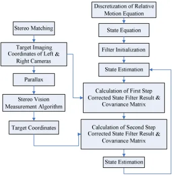
Due to maneuvering of the target spacecraft in formation and disturbance of complex space rays, matching of corresponding points may have an error of several pixels, which will accelerate rapidly with further distance. Considering that single image can provide more stable orientation measurement without big error, a two-step filter algorithm based on Kalman filter is developed: Firstly, get first step filter with orientation measurement and intermediate state estimation with Kalman filter algorithm; secondly, correct the intermediate state with the stereo vision measurement, and obtain the second step filter result. During the second filter, considering the error of the stereo vision measure system is in direct ratio with the square of distance, in order to improve the navigation precision of the filter algorithm, weutilize the relative state estimation to update the measurement noise square matrix, the arithmetic flow chart is shown in the Fig. 2:
Fig 2. Relative navigation algorithm sequence chart
The algorithm in detail is as follows:
(1) Initialization of filter: providing the filter initial valueXˆ (0 | 0), P(0 | 0)
(2) Deduce calculation: k=1, 2,... State estimation:
ˆ( | 1) ˆ( 1 | 1)
X k k− = ΦX k− k−
( | 1) ( 1| 1) T
P k k− = ΦP k− k− Φ + ( 1) T
Q k
Γ − Γ
Stereo vision measurement estimation: ˆ ( | 1) ˆ( | 1)
stereo s
Z k k− =H X k k−
Orientation measurement estimation: ˆ ( | 1) [ ( |ˆ 1), ]
ang ang
Z k k− =h X k k− k
(3) First-step correction of state using orientation measurement.
Calculating measuring error and covariance matrix: ˆ
( ) ( ) ( | 1)
ang k Zang k Zang k k
ε = − −
( | 1) T ang ang ang ang
S =H P k k− H +R
Calculating the filter gain:
1
( ) ( | 1) T ( ) ( )
ang ang ang
K k =P k k− H k S− k
Calculating the state filter value with first-step correction and the covariance matrix:
ˆ
( | ) ( | 1) ang( ) ang( )
X k k =X k k− +K kε k
( | ) ( ang( ) ang( )) ( | 1)
P k k = −I K k H k P k k−
(4)Second step correction of state with the stereo vision measurement.
Calculating measuring error and covariance matrix: ˆ
( ) ( ) ( | 1)
stereo k Zstereo k Zstereo k k
ε = − −
( | 1) T
stereo stereo stereo stereo
S =H P k k− H +R
Calculating the filter gain:
1
( ) ( | 1) T ( ) ( )
ang ang ang
K k =P k k− H k S− k
Calculating the state filter value and covariance matrix with the second step correction:
ˆ ( | ) ( | ) stereo( ) stereo( )
X k k = X k k +K k ε k
( | ) ( stereo( ) stereo( )) ( | )
P k k = −I K k H k P k k
4. Numerical Simulation
the baseline is combination of 0.5m and 1m, then the relationship of measurement error ∆z and distance Z is shown as Fig.3.
Fig 3. The relationship of the measure error and distance Z
According to Fig. 3, the error accelerates rapidly with further distance, which can be reduced by selecting proper focal distance and baseline. The baseline can not be too long considering the view field of camera.
Assume the initial orbital parameters of major spacecraft in formation flying are: semi-major axis of orbit 20182km, orbit eccentricity 0.001105, orbit inclination 50°, right ascension of ascending node 10.31°, argument of perigee 45.72° ,mean anomaly 134.4° ; the initial orbital
parameters of assistant spacecraft are: semi-major axis of orbit 20181.8km, orbit eccentricity 0.0011, orbit inclination
50.2°, right ascension of ascending node 10.315°, argument of perigee 45.713°, mean anomaly 134.3°. Now we just take disturbance of earth’s take J2 into account when we
calculate the true relative position and velocity of two spacecrafts.
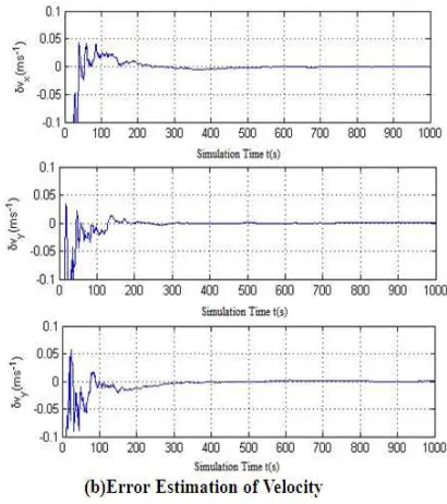
Fig 4. Relative state estimation
Discretizing the relative movement equation in inertial frame as the state equation of the system, the relative position and velocity estimation of two spacecrafts can be obtained by using Kalman filter.
Define that the estimations of relative position errors are
∆
x
,∆
y
,∆
z
, the estimations of relative velocity errors are ∆vx , ∆vy , ∆vz . Based on the above simulationcondition, the initial state errors of position and velocity are 7m and 0.2
m s
/
, and the simulation result of 1s sampling cycle is show as Fig. 4.According to above figures, the initial filter error is bigger while the position error constringes to about 1m in 100s and the convergence of velocity error is rapidly. According to the process of entire simulation, relative position error is no more than 1% of real value which meet the demand of relative navigation parameter of formation flying. At the same time, the different initial simulation inputs are given, and there are same similar results. It shows that the algorithm has enough stability, can be used in spacecraft formation flying.
5. Conclusion
Acknowledgements
This study is financially supported by the National Natural Science Foundation of China (11172235, 51177135), the Doctorate Foundation of Northwestern Polytechnical University (CX201305) and the Doctoral Fund of Ministry of Education of China (20106102110003).
References
[1] Hablani H B, Tapper M, Dana- Bashian D. Guidance algorithms for autonomous rendezous of spacecraft with a target vehicle in circular orbit [R]. AIAA -2001 - 4393 ,2001.
[2] Roberto Alonso, John L Crassidis, John L Junkins. Vision- Based Navigation for Formation Flying of Spacecraft[R]. AIAA Guidance, Navigation and Control Conference, Denver, CO, August 2000, AIAA- 2000-4439.
[3] Junkins J L, Hughes, Wazni, et al., Vision-Based Navigation for Rendezvous, Docking and Proximity Operations[R]. 22nd Annual AAS Guidance and Control Conference, Breckenridge, CO, Feb. 1999, AAS 99-021.
[4] Zhang Shuqin, Space Rendezvous Measurement Technique and Engineering Application, Beijing, China Astronautic Press, 2005, 17-20(in Chinese).
[5] Grosso E, Sandini G, Tistarelli M. 3D Object Reconstruction using Stereo and Motion Systems, Man and Cybernetics, IEEE Transactions on. Nov.-Dec. 1989, 19(6), 1465 – 1476.
[6] Bradley C, Kurada S. Industrial Inspection Employing a Three Dimensional Vision system and a Neural Network Classifier [R]. Communications, Computers, and Signal Processing, 1995. Proceedings. IEEE Pacific Rim Conference on.1995, 505 – 508.
[7] Yingen Xiong,Quek F. Machine vision for 3D mechanical part recognition in intelligent manufacturing environments. Robot Motion and Control, 2002, 441 – 446.
[8] Liu Jiayin, WANG Zhong li, JIA Yun de, Error analysis of binocular stereo vision system, Optical Technology, 2003, 29(3): 354-357(in Chinese).
[9] Zhang Guangjun, Machine Vision, Beijing, Sicence Press, 2005, 99-105(in Chinese).
[10] Bouabdallah S, Becker M, and Siegwart R. Autonomous Miniature Flying Robots: Coming Soon! Research, Development, and Results. IEEE Robotics & Automation Magazine, 2007; 14(3): 88-98.
[11] Erginer B, and Altuğ E. Modeling and PD control of a Quadrotor VTOL vehicle. Proceedings of the 2007 IEEE Intelligent Vehicles Symposium. Istanbul, Turkey, June 13-15, 2007.
[12] Kim J, Kang MS, Park S. Accurate Modeling and Robust Hovering Control of a Quadrotor VTOL Aircraft. Journal of Intelligent & Robotic Systems, 2010; 57: 9-26.
[13] Yoon K J, Goo N S. Development of a Small Autonomous Flying Robot with Four-Rotor System. The 15th International Conference on Advanced Robotics. Tallinn, Estonia, June 20-23, 2011.
[14] Hamel T, Mahony R, Lozano R, Ostrowski J. Dynamic Modelling and Configuration Stabilization for an X4-Flyer. Proceedings of the 15th Triennial IFAC World Congress. Barcelona, Spain, July, 2002.
[15] Hoffmann G, Rajnarayan D G, Waslander S L, Dostal D, Jang J S, and Tomlin C J. The Stanford Testbed of Autonomous Rotorcraft for Multi Agent Control (STARMAC). Proceedings of the 23rd Digital Avionics Systems Conference. Salt Lake City, UT, November 2004.
[16] Nice E B. Design of a Four Rotor Hovering Vehicle. Master’s Thesis, Cornell University, 2004.
[17] Hoffmann G M, Huang H, Waslander S L, and Tomlin C J. Quadrotor Helicopter Flight Dynamics and Control: Theory and Experiment. Conference of the American Institute of Aeronautics and Astronautics, August 2007, Hilton Head, South Carolina.
[18] Tayebi A, McGilvray S. Attitude Stabilization of a VTOL Quadrotor Aircraft. IEEE Transactions on Control Systems Technology. Vol. 14, No. 3, May 2006.
[19] Kis L, Regula G and Lantos B. Design and Hardware-in-the-loop Test of the Embedded Control System of an Indoor Quadrotor Helicopter. International Workshop on Intelligent Solutions in Embedded Systems. July 2008.
[20] Hughes P. Spacecraft Attitude Dynamics. New York: Wiley, 1986.
[21] Fay G. Derivation of the Aerodynamic Forces for the Mesicopter Simulation. Stanford University, February 14, 2001.
http://adg.stanford.edu/mesicopter/progressreports/mesicopt eraeromodel.pdf.
[22] Anderson J. Fundamentals of Aerodynamics. New York: McGraw-Hill Book Company, 2001; 20-26.