ISSN: 2231-5381 http://www.ijettjournal.org Page 144
Adaptive Beam Synthesis for Phased
Array Antenna
Subhra Chakraborty#1, Sahitya Thyadi#2, Pradeep Kumar S#3 , Sahana L R#2, Meghana K#2
#1
Assistant Professor, #2Students, #3Assistant Professor
1,2,3,4
Department of telecommunication, Sir M. Visvesvaraya Institute of Technology, Bengaluru, Karnataka, India
Abstract — This paper details the development and
provides custom-made computer application software that evaluates antenna parameters. The applications are written in Matlab v6.5 for the following purposes: Linear and Planar Antenna Array Analysis & Synthesis, with an added feature of Null Synthesis. Radar Systems require high resolution performance to differentiate between two very closely placed targets. An improved adaptive beamforming technique of antenna arrays is introduced. Smart antenna is the most efficient leading adaptive beamforming technique for maximum coverage, null steering, offer higher system capacity and improved quality of the service compared to other antennas. This project is intended to fulfill the requirements of processing an array used to synthesize array antennas.
Keywords — Matlab, Nulling, Linear array, Planar Array
I. INTRODUCTION
The present needs for expanded array research, development, and production are due to increasing demands for higher performance systems. These include the need for agile beam tactical radars to acquire and track more targets than possible with reflector antennas, the need for defense against military counter-measures using beam agility, deterministic and adaptive pattern control, and the need for conformal scanning antennas for high performance [1] .
Since arrays are expensive, it is a practical fact that they are selected only when conventional mechanical systems cannot adequately do the job. Phased Array has been used in field as diverse as Radar, Communications, Electronic Warfare, & Radio Astronomy. Phased Array continues to contribute to the defence of many countries and valuable platforms such as ships & airplanes critically depend on Phased Array based radars for their survival. It is very difficult to design radar systems without the knowledge of Electronic Warfare that includes the passive sensing of the environment, specifically ECM & ECCM in addition to ESM (Electronic Support measures) [2] . ESM systems are dedicated to remotely sense the environment. Also one does not want to reveal one‟s presence in the course of sensing the environment with the aid of radar [3].Electronically steerable phased arrays are of
interest because they can provide agility, rapid beam steering, simultaneous surveillance & multi-target tracking and multiple functions.
It is also capable ofproviding multiple beams. In the civil sector phased array radars are widely used for Air Traffic Control systems [4]. These are the factors that have made the Phased Array Antenna highly competent.
Here we directly research the problem of nulling in a Phased Array Antenna by trying to place nulls in the beam pattern depending upon the location of the jammers. A radar system may be jammed by a remote signal source that intentionally creates the appearance of a false target or by transmitting large amounts of energy intended to saturate a radar receiver. Interference jamming can come from side lobe or from main lobe directions. Many attempts have been made to suppress jamming of radars [5] [6].
II. SOFTWARE REQUIREMENTS
A. SOFTWARE DEVELOPMENT CYCLE
Fig 1: Software development cycle
Requirement Phase: The user or customer prepares this document. The user puts forth the specific information, what the software product is to do.
Design Phase: The design phase is characterized by the conversion of the requirements document to a detailed design specification. This cannot go ahead until the requirements have been fully understood or defined. Often in the design phase some problems prop up like the requirements that cannot be met with current technology or the unavailability of
resources. Problems such as these require changes in the requirement phase. The user must approve such modifications.
ISSN: 2231-5381 http://www.ijettjournal.org Page 145
function in the design phase, a programmer can now writethe code in what is treated as the programming phase. Test Phase: Acceptation or Rejection of the software is based on how well it fares against the tests. This phase is completed when the criteria established in the requirement phase are satisfied.
2019
B. MATLAB PROGRAMMING
Modern Antenna Array systems are becoming increasingly more complex. Such systems are too expensive to be built just to see whether the information extracted is accurate within limits of the tolerable error. So computational simulation tool has to be developed. A simulation study of the array antenna is almost a necessary prerequisite to check the soundness of the design and performance predicted. Hence a software package for Antenna Synthesis & Analysis was developed using MATLAB. First a programming approach was adopted to make the entire software structure to be expandable and flexible. Later it was rooted into a GUI (Graphical user interface). However, this software performs the simulation of Antenna Array with Nulling techniques and the results are later used for other applications. One of the commercially available software (MATLAB) was used for developing the simulator. The simulator can handle linear and planar array antennas. In order to get low-side lobe patterns, the program features 10 different amplitude tapers. For array synthesis the choice can be made between Uniform, Cosine, Raised Cosine, Cosine on a Pedestal, Hamming, Blackman Harris, Dolph-Chebyshev and Taylor. Apart from computing the 2D and 3D far field radiation pattern, it can also extract the directivity, the position of the main beam, 3 dB beam-width and RMS SLL from the results of the radiation pattern. We can also obtain these results in a high-resolution mode by decreasing the step size for computation. This simulator can simulate various types of errors, such as random or systematic phase and amplitude deviations in the array excitation, phase shifter quantization, element location displacements and structural deformation (z axis) of the array. Various Nulling algorithms have been used to synthesize nulls in the direction of the interferences. Sector nulling can also be achieved by imposing a sufficient number of equispaced nulls in the direction of wideband interference. This simulator incorporates a state-of-the-art GUI and provides a high degree of user friendliness.
C. GRAPHICAL USER INTERFACE DEVELOPMENT
The „Design by Simulation‟ concept always emphasizes the use of a very good graphical user interface. The idea behind this concept is that the user, who may or may not be familiar with the implementation (the software architecture and its implementation), should not be bogged down by trivial implementation details.
Rather, the user should be able to get in to the problem straightway and evaluate the system from the perspective of the application. To help the user in this direction, it is planned to provide visual formalism of the problem and environment so that the user can select the scenario, environment and the strategy on the click of a button, rather than writing a series of commands.
In order to optimize execution speed, the program was mainly coded as matrix operations. In particular, the numerical far-field computation and the data visualization parts were programmed in this way. For MATLAB this is the
favorite approach since it is matrix oriented programming language. The use of matrix or vector operations instead of scalar ones results in a very compact code compared to the coding in FORTRAN or C which is therefore also much easier to debug or to maintain. The programming of the GUI including the dialogue windows was the most time consuming part of the software development. These two parts of the program incorporate also the majority of the coding statements.
D. SOFTWARE REALIZATION
The software performs calculation and displays the array performance measures. The 3 main functions that the software performs are
Linear Array Analysis and Synthesis
Planar Array Analysis and Synthesis
Nulling in Linear Array
Analysis: This function takes as input the amplitude and phase data file along with the geometry of the array and performs calculation and displays the results.
Synthesis: This function takes as input the array configuration along with the taper type and scan direction and performs calculation and displays the results.
Nulling: This function takes as input the number of jammers and the jamming direction and performs calculation and displays the results.
E. GRAPHICAL REPRESENTATION
Graphical presentation of the results is viewed as 2D and 3D plots
Rectangular plot
Polar plot
Surf plot
Contour plot
Intensity plot
Rectangular Plot: This function plots amplitude against azimuth/elevation. This plot also displays the following parameters:
Scan Direction
Beam width
Left Null
Right Null
Left Side Lobe Level
Right Side Lobe Level
Average Side Lobe Level
Directivity
Peak Side Lobe Level
Polar Plot: This function obtains polar plot of amplitude against azimuth/elevation.
ISSN: 2231-5381 http://www.ijettjournal.org Page 146
Contour Plot & Intensity Plot: Contour plots plot thecontour lines of the radiation pattern and the intensity plot plots the filled contour plot.
III. IMPLEMENTATION
There are two aspects of array design that determine their performance criteria. First, their geometry establishes basic constraints upon their operation. Linear arrays can resolve only one angular component (). In a planar array, the boundary of the array and the element geometry are important. Let us assume that the antenna under investigation is an array of infinitesimal dipoles positioned along x-axis, The Array factor for a linear array is given as
AF =
1 0 sin N n jd n n
e
w
,2
2
where is the pattern angle
n
w
= weight vectordn =
1
)
2
(
n
N
kd
k =
2
(wave number)
= Wavelengthd = Inter-element spacing in mm N = Number of elements in the array
The Array factor of the entire planar array can be written as
AF (,) =
M m N n d d j mn n m
e
I
1 1 sin sin cossin
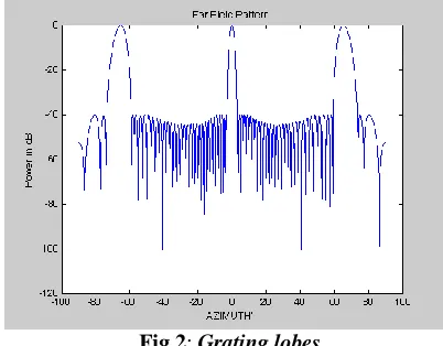
Array pattern synthesis has long been of interest to antenna designers, which require variable complex weights, variable phase shifters, or variable attenuators at the radiating elements of the array. Array Synthesis deals with obtaining the Array Factor by determining the array configuration and element feedings. The fundamental assumption in synthesis is; one begins by specifying the desired array pattern, number of array elements, inter element spacing and length of the array.
Fig 2: Grating lobes
Array pattern synthesis has long been of interest to antenna designers, which require variable complex weights, variable phase shifters, or variable attenuators at the radiating elements of the array. Array Synthesis deals with obtaining the Array Factor by determining the array configuration and element feedings
.
The synthesis question is basically, what isthe requisite current distribution (taper) at each sensor in an equispaced array.Most of the well-known distributions that are used are Dolph-Chebyshev and Taylor.
Fig 3:
Beam patterns of Dolph-Chebyshev and Taylorn
Beam Pattern Calculation
In many applications it is required adjust the gain and phase at the output of each sensor to achieve a desirable beam pattern. The beam pattern of an array is a key element in determining the array performance.
Thus,
B() =
sin 2 2 1 d N j
e
1 0 sin 2 * N n d jn ne
w
,-
NULLING
This approach assumes that there are certain points in the beam space where there are interfering signals (e.g., jammers). There are various ways to counter these jammers, like side lobe cancellation, is achieved with a mechanically scanned reflector antenna. Nulls are achieved in “beam space” by using one or more formed beams properly attenuated to adaptively cancel noise sources rather than using one or more unidirectional elements.
If there are J noise sources to be nulled, the angular location is found in a conventional manner and J directive beams are then formed to adaptively cancel each source. Using different algorithms, cancellation is achieved without disturbing the main beam.
We design weighting so that the response is zero in these directions.
Few approaches are:
Amplitude Nulling
Phase Nulling
Sector Nulling
Adaptive Nulling
ISSN: 2231-5381 http://www.ijettjournal.org Page 147
IV. SOFTWARE COMPREHENSIONTo start the simulator on a MATLAB 6.5 version, choose the current directory where the simulator is present. The directory you specify will be the current working directory when using the software. The prompt (>>) in the Command Window indicates that MATLAB is ready to accept input from you. When you see the >> prompt, type „START‟ in the command window and follow the instructions. The flow chart shown helps you to navigate through the software.
Simulation of Linear Array
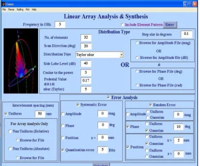
The user has to enter relevant data in the edit boxes based on his requirement of the array antenna as shown in Fig 5.1. Click the arrow of the pop-up menu to see the list of choices of Distribution type or click the radio button to browse a premeditated file. After the antenna array is configured various types of errors can be introduced to them by checking the check boxes. He must also take care that by giving very erroneous value will result in a very bad output. After all the information are fed in push the „Calculate‟ button.
Fig 5: GUI Page of Linear Array Synthesis with Taylor
nbar taper, 20 scan, uniform spacing
Various graphical results can be viewed when the user selects the plot button from the menu bar. Help provides complete instruction for using the software. Systematic (Quantization) and random (Phase & Position) errors have been introduced to observe the array under ideal and error conditions.
Fig 6: Polar plot results of Linear Array
Fig 7: Far-Field Pattern results of Linear Array
Simulation of Planar Array
In Planar Array Synthesis Distribution Type has to be chosen for both Azimuth and Elevation Directions. Scanning directions can also be chosen to be anywhere on the plane. Since planar array has to undergo more computations compared to linear array the compilation time is also more. Hence a wait bar will show the progress of compilation. After compilation, 3D and 2D (Azimuth and Elevation cut) graphical results can be viewed.
ISSN: 2231-5381 http://www.ijettjournal.org Page 148
Fig 9: 3D Pattern of Planar Array
Simulation of Nulling in Linear Array
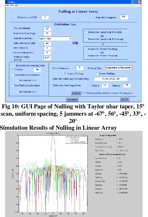
To synthesize Nulls in a Linear array, the user has to enter relevant data, choose the number of jammers, the nulling type and the jamming direction. If the nulling directions are discrete, Linear Nulling can be implemented and if it is wideband jamming Sector Nulling can be implemented by specifying the jamming sector.
By generating random jamming direction, nulls can be placed in those directions. Along with the ideal and null pattern, cancellation pattern can also be viewed in the far-field pattern result.
Fig 10: GUI Page of Nulling with Taylor nbar taper, 15 scan, uniform spacing, 5 jammers at -67, 56, -45, 33,
-20
Simulation Results of Nulling in Linear Array
Fig 11:
Far Field Pattern Results for NullingFig 12:
Polar Plot Results for NullingV. ADVANTAGES
1. Steerable beam (radiation direction change).
2. Improved adaptive pattern nulling
3. Super-resolution
4. Increased Dynamic Range
5. Antenna self-calibration and ultra-low side lobes
6. Graceful degradation
VI. CONCLUSION
A sophisticated Antenna Array Simulator software package for the Design and Analysis of Linear and Planar Array Antennas was developed in Matlab 6.5. The package can be used to synthesize nulls in array antennas. The simulator package is implemented in a user friendly, menu driven state-of-art GUI.
The simulator is an extremely useful tool for an antenna designer to decide upon various parameters of antenna to design an antenna array, which should meet the stringent requirements of radar.
The objective of the project has been realized with the implementation and successful validation of the simulator. Future Advancements
Capabilities of the simulator can be expanded to be able to handle mutual coupling problems, synthesis of shaped beams and to add more efficient algorithms for synthesizing adaptive arrays.
VII. REFERENCES
[1] Qing Han, Victor Briend, Takashi Ohira, “Evaluation of the Adaptive Beamforming Capability of an ESPAR Antenna Using the Genetic Algorithm”
[2] Adaptive Transmit and Receive Beamforming for Interference Mitigation”
[3] Rongfeng Li, Can Rao, Lingyan Dai, Shifeng Zhao, “Adaptive Beamforming Algorithm of Planar Array Based On One-dimensional Auxiliary Beam”
[4] Xinyu Sun, Xiaohua Lian, Jianjiang Zhou, “Robust Adaptive Beamforming Based on Maximum Likelihood Estimation”
[5] IEEE Standard Definitions of Terms for Antenna, IEEE Std 145-1983
[6] Constantine A.Balanis “Antenna Theory Analysis & Design”, 2nd Edition, John Wiley & Sons, USA, 1997.
[7] http://www.ijettjournal.org/archive/ijett-v48p251
[8] Merrill I.Skolnik “Introduction to radar systems”, 3rd Edition, Tata
McGraw-Hill Publishing Company Ltd, 2001.
[9] R.C.Hansen “Sign`ificant Phased Array Papers”, Artech House Inc, MA, USA, 1973 Edition.
[10] Nicholas Fourikis “Phased Array Based Systems & Applications”, John Wiley & Sons, USA, 1997