Vol. 3, Issue 7 (July. 2013), ||V5|| PP 38-42
Comparative Analysis of Multipulse AC-DC Converter Using
Zig-Zag Transformer
Ms.Shruti Gour, Mr .Saurabh Gupta
Ms.Shruti Gour, Mr.Saurabh Gupta ,
Abstract:- This paper presents a novel configuration of separate zigzag transformers based 18-pulse AC –DC converter for improving the ripple factor & isolation of three phase uncontrolled rectifier, this approach eliminates the complexity required to design a complicated auto transformers or isolated multi winding transformer as used with other systems. The paper also presents the comparison among 12 pulse and 6 pulse AC - DC converter for different parameters like ripple factor, harmonic distortion in input current for unbalanced supply voltage, efficiency of the converters, power factor variations of input power supply all these parameters are compared for no load light loads & full load conditions we further extend our simulation for measuring the effects of different type of filters like L, C & LC the simulation results shows some useful & interesting results which can be used for developing or selecting the best configuration for practical developers.
Keywords: - 18-Pulse ac–dc converter, zigzag transformer, three phase rectifier.
I. INTRODUCTION
As we know that DC current is the basic requirement of many of the high power electrical machines like series or shunt DC motors, BLDC motors etc the proper operation of these machines need a smooth DC supply because the most of the distribution system provides AC supply hence a proper circuit is needed for converting AC to DC although many methods are available for this purpose the method selection is not a difficult task in the case of smaller load because adding a simple filter can enhance the performance of poorly selected rectifier but for the large load condition it can be very difficult because for large loads we need very heavy filter circuit which is not acceptable hence the selection of multi pulse converters are necessary another problem related to power systems is harmonic distortion caused by nonlinear loads because applications of nonlinear devices are continuously increasing in industries. Generally two techniques are used to solve the harmonic current problems. 1. Active current shaping and 2. Passive current shaping methods. Active current shaping methods requires some energy recycling or redistribution between different lines by using storing (like capacitors) switching & coupling devices controlled by some complex algorithms. Passive current shaping methods employs the passive filters like LC circuits with multi pulse switching configurations to eliminate the selected harmonics. This paper discusses the performance of 6, 12, and 18-pulse diode converters. In multi pulse converters, several six-pulse diode rectifiers are connected either in parallel or in series. Each rectifier is fed by phase shifted secondary windings voltages of a transformer. Increasing the number of rectifiers raises the number of steps in the primary current waveform and produces a sinusoidal shaped supply current flowing into the transformer primary winding. For harmonic mitigation, multi pulse uncontrolled converters are very popular due to the absence of any control system for the power diodes, however, control of output voltage is not possible. On the other hand, multi pulse controlled converters require a control circuit for switching of the thyristors however; modular control concept makes the overall design and circuit realization easier than anticipated from the complexity stand point. This paper presents the simulation of multi pulse diode converters by connecting six pulse rectifiers in series feeding R-L loads. The THD in the input supply current and the ripple in the output voltage are compared.
Many methods based on the multi pulse switching have been proposed which are based on autotransformer or multi winding isolation transformer although both of them provides small size of transformer but need a complex structure also the autotransformer lacks the isolation between input and output & other also can be completely damaged by accidental overloading of one of the any phase because all primary windings are common.
II. PREVIOUS WORK
the magnetics. The design of the autotransformer is carried out for an 18-pulse ac–dc converter feeding a vector controlled induction motor drive (VCIMD). Moreover, the autotransformer design is modified for making it suitable for retrofit applications, where presently a 6-pulse diode bridge rectifier is used. The effect of load variation on VCIMD is also studied and the performance of the proposed 18-pulse ac–dc converter is compared in terms of different power quality indices on both ac as well as dc side with other ac–dc converters. A laboratory prototype of the proposed autotransformer based 18-pulse ac–dc converter feeding a 10-hp induction motor drive is developed to verify the design and simulated results. And the results shows that the THD of supply current at full load is 9.23% and that at light load is 15.32%, whereas the power factor under these conditions is 0.981 and 0.976, respectively. Another method is proposed by Maryclaire Peterson and Brij N. Singh [4]. This paper deals with input current shaping of uncontrolled and controlled rectifiers using multi pulse current shaping concept. The rectifier circuits investigated in this paper feed R-L loads. The developed mathematical model of multi pulse converters emulates the behavior of various multi pulse current shaping methods. The mathematical model is capable of replicating the operating behavior for converters with any number of rectifiers; 6, 12, 18, 24, 36, and 48-pulse diode/thyristor converters. To reduce the transformer rating, autotransformer based multi pulse converters have been reported in the literature [5]. In the autotransformer, the windings are interconnected such that the kVA rating of the magnetic coupling is only a fraction of the total kVA of the VCIMD. Different configurations of autotransformer based 18-pulse ac–dc converters have been reported in [6]–[7] for reducing the total harmonic distortion (THD) of ac mains current improved even under light load conditions.
III. PROPOSED WORK
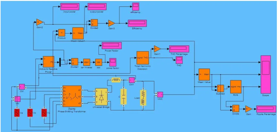
Because we have to perform the comparison for different configuration the figure 1 shows the basic model of six pulse uncontrolled rectifier which is also used as base unit for 12 and 18 pulse system. The simulink model shows the zigzag transformer at although for six pulse system it is not required but because for higher pulse the proposed model consists of zigzag transformers with different phase shifts we selected this with zero phase shift instead of normal transformer to achieve the fair comparison because the change in type of transformer may cause the small change in its parameters. The rectifier is designed for 10KVA rating at 230V 50Hz AC. The transformer used is also rated for same with turn ratio of one & to measure the different parameters of the rectifier like THD, Ripple ratio etc. some other components are connected with the circuit. In circuit for analysis a R-L load is connected at the output of the rectifier which can be varied for measuring the condition of rectifier at different load conditions the base circuit also uses passive L-C filters as shown in figure although for the simplicity we are showing one model but for analysis all configuration of filters are considered. The ratings of the components selected for the simulation are as follows
1. Voltage source: 230V AC 50Hz. All three sources are shifted by 120 degree in phase relatively.
2. Transformer: Zigzag for 6-pulse zero degree phase shift, for 12 pulse 30 degree phase shift & for 18 pulse 20 degree phase shift. The transformer is rated
10KVA at 230V 50Hz the turn ration is selected as one.
3. Universal Bridge: three arms six diode standard bridge with snubber resistance of 100K ohms & capacitor of 0.1 micro farad.
4 Load: the load is selected according to given expression For full load condition
103*K*P = (K*1.35*230)2/R…………. (1)
Where K = 1, 2 or 3 according to 6-pulse, 12-pulse or 18-pulse. P represents the factor of loading & equal to one for full load.
Now from expression (1) the value of R can be easily found for different operating condition. The value of L is selected by considering the ratio of stored power to dissipated power. Where stored power = (1/2)*L*I2. & dissipated power = I2R.
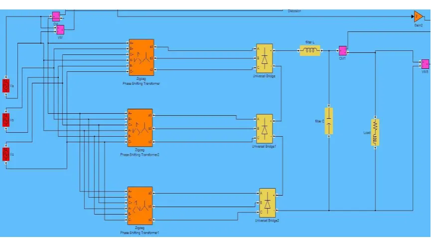
For the 12 & 18 pulse models some measuring blocks are eliminated to fit the figure in page.
Figure 2 Simulink model for 12 pulse converter
Figure 3 Simulink model for 18 pulse converter
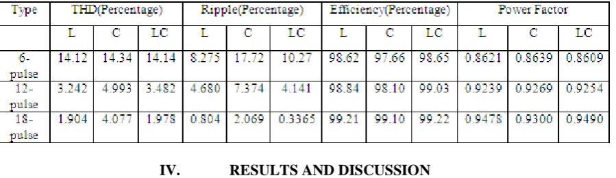
IV. RESULTS AND DISCUSSION
The proposed 12- and 18-pulse ac–dc converters have been modeled and designed for R-L load in MATLAB environment along with Simulink and Power System toolboxes. The overall performance of the converter, with different load fed by a 6-pulse 12-pulse and 18-pulse diode bridge rectifier, are listed in table above. The analysis shows that the supply current waveform along with its harmonic spectrum at full load, showing the THD of ac mains current as 31.3%, which deteriorates to 62.2% at light load (20%), as shown in Fig. 14. Moreover, the PF at full load is 0.935, which deteriorates to 0.807 as the load is reduced to 20%, as shown in Table III. These results show that there is a need in improving the power quality at ac mains to replace the existing six-pulse converter.
V. CONCLUSION
proposed ac-dc converter has shown the flexibility to vary the voltage ratio of the autotransformer for making it suitable for retrofit applications. The performance of the proposed eighteen-pulse ac-dc converter has been found satisfactory under varying load on VCIMD. The proposed ac-dc converter is able to provide close to unity power factor in the wide operating range of the drive. The proposed converter has resulted in reduction in rating of the magnetics leading to the saving in overall cost of the drive. The obtained experimental results on the proposed converter has demonstrated the capability of this converter to improve the power quality indices at ac mains in terms of THD of supply current, THD of supply voltage, power factor and crest factor.
REFERENCES
[1] P.Vas, Sensorless vector and direct torque control, Oxford University Press, 1998.
[2] IEEE Guide for harmonic control and reactive compensation of Static Power Converters, IEEE Std. 519-1992.
[3] D. A. Paice, Power Electronic Converter Harmonics: Multipulse Methods for Clean Power, New York, IEEE Press, 1996.
[4] A. Uan-Zo-li,, F.Wang,D. Boroyevich, F. Lacaux andcA.Tardy,“Comparison of prospective topologies for aircraft autotransformer-rectifier units,” Proc. IEEE, IECON’03, Nov.2003, Vol.2, pp.11211-1127.
[5] D.A. Paice, “Optimized 18-pulse type, AC-DC, or DC/AC, converter system”, U.S. Patent No. 5,124,904, June 23, 1992.
[6] P.W.Hammond, “Autotransformer”, U.S. Patent No. 5619407, 8 April,1997.
[7] D.A.Paice, “Transformers for multipulse AC/DC converters”, U.S. Patent No. 6101113, 8 August, 2000. [8] D.Zhou, L.Skibinski and N.N.Guskov, “Nine-phase transformer,” U.S. Patent No. 6,249,443B1, June19,
2001.
[9] G. R. Kamath, D. Benson and R. Wood, “A novel autotransformer based 18- pulse rectifier circuit,” in
Proc., IEEE IECON’03, 2003,, pp. 1122-1127.