Volume-5 Issue-2
International Journal of Intellectual Advancements
and Research in Engineering Computations
Automatic wiper system with variable frequency
Vicknesh.C1, Aakash.A.E2, Dev.M2, Dinesh.S2, Lisanson.R2 1Assistant Professor, 2UG Students,
Department of Mechanical Engineering, Shree Venkateshwara Hi-Tech Engineering College, Erode, Tamilnadu, India.
Abstract- “Automatic Wiper Control with variable frequency” is a system used to renew the old system from manual to automatic. When it rains, the wiper will wipe automatically. This system is fully controlled using microcontroller system. A windscreen wiper is a device used to wipe rain and dirt from the windscreen. The main function of „Automatic wiper with varying frequency‟ uses sensor and controller system wipes and sweeps the water from the windscreen. The main idea is to construct an automatic wiper using a sensor as a component which is used to sense the raindrops. But the system has been upgraded by considering the existing new problem. Therefore, the second idea is to automatically vary the speed when the intensity of the rain increases.
Keywords—Automobile; Wiper; Sensor; speed control (key words)
I.INTRODUCTION
“Automatic Wiper Control with variable frequency” is a system used to renew the old system from manual to automatic. When it rains, the wiper will wipe automatically. This system is fully controlled using microcontroller system. A windscreen wiper is a device used to wipe rain and dirt from the windscreen. The early wipers invented are operated manually by moving a lever inside the car back and forth. The wipers faithfully keep the window clear, moving back and forth across the windscreen countless time as they sweep the water away. This project is to renew the system from manual to automatic.
The main function of „Automatic wiper with varying frequency‟ uses sensor and controller system wipes and sweeps the water from the windscreen. The main idea is to construct an
automatic wiper using a sensor as a component which is used to sense the raindrops. But the system has been upgraded by considering the existing new problem. Therefore, the second idea is to automatically vary the speed when the intensity of the rain increases.
A. NEED FOR AUTOMATIC WIPER SYSTEM In the present automobiles the number of facilities is much higher. The driver has to concentrate on road while driving, and with increased traffic, things get frustrating. The features in the car like GPRS to trace the route, music system, air condition system etc may drive away the attention of the driver. Thus an effort has been made to reduce the effort put by driver in controlling the speed of the wiper and put more concentration on his driving. Since this system is put into use in many higher end cars and has been successfully working, an effort was made to reduce the cost of the system so that this system can be implemented in common economic cars where a common man can also enjoy the benefits
B. OBJECTIVES
To make sure that this project meets the goals and requirement, the objectives of this project are defines below according to the points:
To upgrade the older cars system by
providing automatic wiping system.
To have varying speed when the intensity of rain changes.
To improve the system by using sensor
.To design a basic program that will fully operate with the system.
To reduce the accidents due to rain
C. SCOPE OF STUDY
The scope of the project that has been used to complete this project is explained as below
Study how to combine the circuit for
sensor, controller and motor.
Design criteria will focus on application, economical aspect and flexibility
The system functions at two speed modes. When the sensor detect water, the system automatically functions and its will stop if the sensor does not senses water
The future of automation will take a part in the wiper system as a safety method.
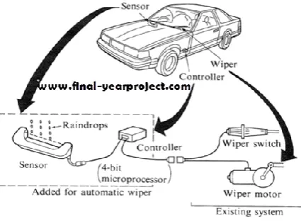
FIG 1.1 Systematic View of the Automatic Wiper System
D.METHODOLOGY
Project planning is the most important phase which is to develop the automatic Control Wiper. In this phase, it is started with the title definition to know what is the main element should be carried out.
Problem identification and clarification is the next step followed by the literature review to find the relevant and related information regarding the car wiper in term of type, function and mechanism. From the information that been collected from past and current research, the development phase proceed by designing the conceptual design.
The design will focus on the mechanism to use for this project where to achieve the
automatic function.
Modification is necessary if there is any problem or element that needs refinement. In order to develop a prototype, the component selection needed to decide on suitable parts or tools as different types of component have different function.
Design evaluation is an important activity
because it needs to evaluate the
appropriateness of design on its functions that provides the features intended. The wiper more simple circuit and simple hardware to reduce the cost.
The component will be use is important things to choose depend on the circuit.
II. COMPONENTS OF AUTOMATIC WIPER SYSTEM
A. SENSOR SELECTION
This method uses a sensor, which consists of two sets of conductors separated by an insulator. When water falls on the sensor, the water conducts the signal and closes the circuit. Then it sends the signals to the next unit to operate the wiper motor. We are using a rain sensor modules which are readily available in the Market.
B. SENSOR SIGNAL INPUT
The sensor signal from various sensor is fed to can Which is convert the amplitude and send it to the 8 bit microcontroller which converts the amplitude Vp of the raindrop signal into pulse-width information. This pulse-pulse-width information is read into a software counter in the microprocessor to determine the degree of rainfall..
C.RAIN SENSOR MODULE FEATURES
The sensor uses the high quality FR - 04 double material, large area of 5.5 * 4.0 CM, treatment of nickel plating and surface, have fight oxidation, electrical conductivity, and life
has more superior performance. With
Figure 3.2 Rain Sensor Module
D. ANALOG COMPARATOR
A comparator module is integrated in the
IC that provides comparison facility between two voltages connected to the two inputs of the Analog comparator via External pins attached to the micro controller.
Figure 3.10 Analog Comparator
E. RAIN LEVEL SENSOR
Rain level Sensor is a highly versatile device for automatic wiping of vehicle windscreen when it is wet due to moisture, raindrops or even mud. It measure the amount of water inside tube with respect to time within the windscreen. When water level are increase with respect to raindrops fall onto the windscreen, then system then activates the wiper to operate in full automatic mode. The main features is Automatic wiper activation and deactivation and Intelligent wipers speed control .
F. STEPPER MOTOR
A stepper motor (or step motor) is a
brushless DC electric motor that divides a full rotation into a number of equal steps. The motor's position can then be commanded to move and hold at one of these steps without any feedback sensor (an open-loop controller), as long as the motor is carefully sized to the application.
Switched reluctance motors are very large stepping motors with a reduced pole count, and generally are closed-loop commutated. DC brushed motors rotate continuously when DC voltage is applied to their terminals.
The stepper motor is known by its important property to convert a train of input pulses (typically square wave pulses) into a precisely defined increment in the shaft position. Each pulse moves the shaft through a fixed angle.
Figure 3.12 Block Diagram of Stepper Motor
Stepper motors effectively have multiple toothed electromagnets arranged around a central gear-shaped piece of iron. The electromagnets are energized by an external control circuit, such as a microcontroller. To make the motor shaft turn, first, one electromagnet is given power, which magnetically attracts the gear's teeth. When the gear's teeth are aligned to the first electromagnet,
they are slightly offset from the next
electromagnet. This means that when the next electromagnet is turned on and the first is turned off, the gear rotates slightly to align with the next one. From there the process is repeated. Each of those rotations is called a step with an integer number of steps making a full rotation. In that way, the motor can be turned by a precise angle.
G. INDEXERS
The indexer (or controller) is a
microprocessor capable of generating step pulses and direction signals for the driver. In addition, the indexer is typically required to perform many other sophisticated command functions.
H. DRIVERS
The driver (or amplifier) converts the
indexer command signals into the power necessary to energize the motor windings. There are numerous types of drivers, with different voltage and current ratings and construction technology. Not all drivers are suitable to run all motors, so when designing a motion control system the driver selection process is critical.
III. METHODOLOGY FOLLOWED
A. HARDWARE DESCRIPTION
The rain sensor is used to detect the
amount of the rain and give the signal to the controller. The ADC in the controller detects the sensor input and gives the signal to the driver circuit. The motor driver actuates the motor to run at high speed or low speed based on the amount of the rain level detected. The rain level sensor will detect the level of water content on the windshield and based on the amount of water deposited on the windshield, the speed of the wiper is controlled.
automatically . In that case, the system will turn on the wiper motor to activate at high speed using the driver circuit. If the level of water content is low, then the wiper motor is activated at low speed. These are the basic building blocks of the hardware besides the resistors and capacitors that are required for any electronic circuit
B.INTERFACING WITH THE TRADITIONAL WIPING SYSTEM
The software used designing and
simulating the test results were Proteus 7.0 and „C‟ 18 MPLAB C language compilers. MPLAB IDE V 8.30+ for complete Development environment. Proteus 7.0 is a Virtual System Modeling (VSM)
that combines circuit simulation, animated
components and microprocessor models to co-simulate the complete microcontroller based designs.
This program allows users to interact with the design using on-screen indicators and/or LED and LCD displays and, if attached to the PC, switches and buttons. One of the main components of Proteus 7.0 is the Circuit Simulation a product that uses a SPICE3f5 analogue Simulator kernel combined with an event-driven digital simulator that allows users to utilize any SPICE model by any manufacturer. Proteus VSM comes with extensive debugging features, including breakpoints, single stepping and variable display for a neat design prior to hardware prototyping.
C. HARDWARE IMPLEMENTATION
The basic control units of the hardware comprises of power supply unit, control switch, wiper motor, rain level sensor ,motor driver circuit and the most important of all PIC controller. Power supply unit maintains the continuous power to the controller and the wiper motor. Control switch is directly connected to the controller. Motor driver circuit is linked with the wiper motor and the controller. The command it gets from the controller is used to either drive the wiper motor or switch it off. Rain detection sensor detects the amount of
water level on the windscreen and accordingly sends the signal to the controller.
D. CONTROL LOGIC
The data processing unit is composed of a microcontroller and an output signal module. The AVR Atmega8 microcontroller was finally selected over the initial TI MSP430 because of its higher output power and number of analog-to-digital
channels. The communication between the
computer programmer and the microcontroller is done via serial peripheral interface bus (SPI). The program executed by the microcontroller.
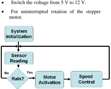
the system is enabled, the system initialization block checks if the sensors are operational, sets the corresponding input and output pins, and determines if the power is high enough to keep the microcontroller running. After performing all the necessary checks, the program reads voltages from the impedance grid sensor and IR sensor in a sequential order.
Figure 4.2 Sensor With Water Varying Electrical Conduction
IV. CODES OF MICROCONTROLLER
A. CODES AND STANDARDS
The team adhered to the codes and standards focused on interfacing the system with the automobile controls. The sensor and the
microcontroller are governed by universal
standards such as the NEC, the National Electric Code . The microcontroller will also abide by the SPI protocol in order to load in a program from the PC. In automobiles, information from one sensor and/or data from one system can be communicated with other systems using multiplex wiring to reduce the number of sensors and the amount of wire used in a vehicle.
Society of Automotive Engineers (SAE) has established as the standard for multiplexing and
data communications in U.S. automobiles.
However, data communications for trucks and On-Board Diagnostics II (OBDII) are based on the
Controller Area Network (CAN) protocol
developed by Robert Bosch GmbH.
The SAE Vehicle Network for Multiplexing and Data Communications Committee has defined three classes of vehicle networks: Classes A, B and C. Class A is for low-speed applications such as body lighting. Class B is for data transfer between nodes to eliminate redundant sensors and other system elements. Class C is for high-speed communications and data rates typically associated with real-time control systems. The project will be considered as a class C application.
V. WORKING OF THE SYSTEM
A.WORKING OF THE CONTROL LOGIC
The Rain sensor is simulated with tap water. A 5 v D.C supply is provided for the rain sensor. The Range of the sensor values obtained is 0.3 V – 3.7 V. The Analog pin of the comparator is connected to the A0 pin of the Microcontroller. The Analog pins 8, 9, 10, 11 are connected to 1,2,3,4 pins of the stepper motor driver circuit for having a desired motor rotation in one direction. Another 2 pins of the stepper motor is grounded.
Switch the voltage from 5 V to 12 V.
For uninterrupted rotation of the stepper motor.
Figure 6.1 Summary of System Control Logic
It takes a lot of force to accelerate the wiper blades back and forth across the windshield so quickly. In order to generate this type of force, a worm gear is used on the output of a small electric motor.
B.WORKING OF WIPER
Wiper blades are like squeegees. The arms of the wiper drag a thin rubber strip across the windshield to clear away the water. When the blade
is new, the rubber is clean and has no nicks or cracks. It wipes the water away without leaving streaks. When the wiper blades age, nicks or cracks form, road grime builds up on the edge and it doesn't make as tight a seal against the window, so it leaves streaks. Sometimes you can get a little extra life out of your wiper blade by wiping the edge with a cloth soaked in window cleaner until no more dirt comes off the blade.
Another key to streak-free operation is even pressure over the length of the rubber blades. Wiper blades are designed to attach in a single point in the middle, but a series of arms branch out from the middle like a tree, so the blade is actually connected in six to eight places. If ice or snow forms on these arms, it can make the distribution of pressure uneven, causing streaks under part of the blade. Some wiper manufacturers make a special winter blade with a rubber boot covering the arm assembly to keep snow and ice out.
C.WORKING OF SENSOR
The sensor incorporated in our project
detects the rainfall and triggers the wiper motor to activate the wiper. The sensor consists of a pair of copper plates of 1 mm thick, separated by a distance of 1 mm. One of the copper plates is connected to a 5 V battery, while the other copper plate is connected to a micro controller which in turn is connected to the wiper motor.
The working of automatic rain operated wiper is based on conductive method. This method uses a conductive sensor, which consists of two sets of contacts separated by an insulating material or an insulator. When water falls on the sensor, the water conducts the signal and thus it completes the circuit.
D. WORKING OF MICROCONTROLLER
The microprocessor system is
implemented with a single chip microcontroller. This could be called microcomputer, as all the major parts are in the IC. Most frequently they are called microcontroller because they are used they are used to perform control functions.
A microcontroller is a Computer-On-A-Chip, or, if you prefer, a single-chip computer. The microcontroller and its support circuits are often built into, or embedded in, the devices they control.
Today microcontrollers are very
commonly used in wide variety of intelligent products. For example most personal computers keyboards and implemented with a microcontroller.
VI. CONCLUSION
can be integrated in Economic class cars. Automation with variable frequency can be integrated with incumbent wiper system.
The following DISADVANTAGES are inferred during the project simulation.
1].The Nickel coating is getting oxidized and rust is forming on the surface which may hamper the sensing aptness of the Rain sensor module.
2].The sensor gives only 3 set of analogue values for the various rain intensities. Thus with this sensor only 2 variables speed are feasible.
Thus, this low cost and integrated automatic wiper system with variable frequency greatly reduces the hinder for the driver. By using this system, the user can also control manually along with automatic control of the wiper system. The Older version of car wiper system has been upgraded.
Users do not need to face difficulties in controlling the wiper when it is raining heavily. When the engine is started, the sensor circuit is functioned and it is controlled by a microcontroller.
REFERENCES
W.BOLTON, “Mechatronics: A
Multidisciplinary Approach: Electronic Control Systems in Mechanical and Electrical Engineering “
R.K.Rajput, “Mechatronics”
International Journal of Application or
Innovation in Engineering & Management (IJAIEM) ISSN 2319 – 4847
International Journal of Computer
Technology and Electronics Engineering (IJCTEE)(An ISO 9001: 2008 Certified International Journal) ISSN 2249-6343
Sonali B. Madankar , Dr.Milind M.
Khanapurkar , “Intelligent Rain Sensing using Automatic Wiper System
American Journal of Engineering
Research (AJER) e-ISSN : 2320-0847 pISSN : 2320-0936
M.UCAR,H.ERTUNC, AND O.TURKOGLU,
“THE DESIGN AND IMPLEMENTATION OF
RAIN SENSITIVE TRIGGERING SYSTEM FOR
WINDSHIELD WIPER MOTOR,” IN IEEE
IEMDC,2001, PP.329-336.
G. Muller, “Windshield Wiper System
with Rain Detector,” U.S. patent no. 5015931, issued June 11, 1991
Wong Sai Hoong & Gilbert Thio,”Design