Verification Methodologies for Vector
Processor Engines
Alluri Ramadevi1, P. Raveendra Babu2, S.Anil3
1
PG Scholar, Dept. of ECE, CMRCET, Hyderabad, Telengana, India
2
Assoc Prof, Dept. of ECE, CMRCET,Hyderabad, Telengana, India
3
Asst Prof, Dept of ECE, CMRCET, Hyderabad, Telengana,India
Abstract-
Verification of a vector processor engine is complex and time consuming task. A key aspect of vector architecture is the single-instruction-multiple-data (SIMD) execution model. Due to its Data parallelism, Instruction level parallelism and on-chip memory it became more complex compare to scalar architecture. This type of complex designs needs efficient and extensive verification. Majorly the verification process focuses on functional coverage to produce accurate designs. There are different standard methodologies exist in verification like e, OVM and UVM etc. UVM came up with more advantages out of all existing methodologies. This paper tells about verification, its methodologies exist in present scenario and also focuses on Verification of a Vector processor engine (eg: Multi Data Path Processor) using UVM methodology to detect bugs early in design stage.
Keywords: Functional Verification, History of
Verification, UVM Environment Implementation, UVM Methodology, Verification.
I. INTRODUCTION
Verification is a process that ensures specifications those are preserved in the implementation. It is used to find out the bugs in a design phase. As the design complexity increases, there will be more chances of finding bugs in the design and requires extensive and efficient verification. Functional Verification aims at functionality of the design and produce error free designs. Functional verification [6] process defines to check DUTs behavior on different inputs
combinations with maximum possible test cases to cover all specification requirements.
Figure Error! No text of specified style in
document.-1: Verification cycle
Systemverilog [1] [3] [4] language is used mainly for implementing Verification Environment. Systemverilog provides Object Oriented programming concepts to produce reusable verification components.
II. HISTORY OF VERIFICATION
METHODLOGIES
The first methodology [5] came out was eRM (e reuse methodology) in 2001 by verisity design and it was used with e hardware verification language. After eRM methodology RVM (2003), VMM are released by Synopsys. Next generation methodologies are URM, AVM, OVM and UVM by cadence and mentor graphics. Till 2006 all released methodologies are tied up with vendor and vendor only can create test bench so that these methodologies were not used by people efficiently. AVM was invented in 2004 and it is a quite open source compare to previously released methodologies. OVM comes from both AVM and URM methodologies invented by cadence and mentor graphics in 2008. UVM has come from both OVM and VMM by Accellera. UVM is open source methodology and it provides friendly
programmability using predefined functions compare to other methodologies.
III. UVM ENVIRONMENT
STRUCTURE
The general Verification steps to be followed to verify a design as mentioned below
1. Understanding the design specification. 2. Stimuli should be passed to the design to
have 100% coverage.
3. Component or code to check whether output is matching with expected output.
4. Tracking element to update or show the results how far DUT has been exercised. Methodology provides all these requirements to do verification and to create reusable components. Methodology makes verification process simpler and faster due to its predefined classes and features.
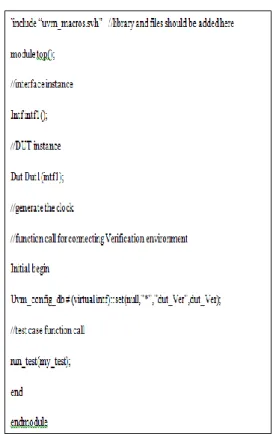
Figure 3-1: UVM Environment Structure A. Top Module:
Top module consists of static structures (Design under Test (DUT) and Interface instances), clock
generation, test case function call and UVM function call to connect Dynamic environment (UVM Verification environment) and DUT for communication.
B. Test:
Test holds environment and its sub components. my_test file contains list of test cases, environment object creation and instances. In consideration for Vector processor the test cases can be written for memory modules to test each location, the communication between memory module to other modules in design and the instructions present in processor.
C. Environment:
It consists of verification sub components object creation and connections between components.
D. Agent:
Agent is sub component in Environment and it holds rest of the components like sequence, sequencer, driver, monitor, scoreboard and coverage.
Seq_item_port of the driver is connected with seq_item_export in sequencer to pass the stimuli from sequencer to driver. Seq_item_port and seq_item_export are explained in later sections. Monitor is connected with analysis port to get responses from DUT.
E. Sequence:
Sequence block used for generating stimuli. Stimuli will be generated using random function calls. Sequence has to be implemented using push method to pass stimuli to other components. For Vector Processor the Sequence should be implemented to produce set of data in one clock cycle.
F. Sequencer:
It used for passing stimulus to driver component. Virtual sequencer is used for sending stimulus from sequencer to driver and its instance will be done in my_test or environment. Sequencer can be defined as follows:
G. Driver:
Driver is used for passing stimulus to DUT using virtual interface. The precaution should be taken to pass set of signals at a time to DUT without any delay in Vector Processor Verification Environment.
H. Monitor:
Monitor works as collector and it collects responses from DUT and passes to scoreboard and coverage.
I. Coverage:
It is used to know how much design has been exercised. The input stimuli should be passed to coverage module so that it tells how much percentage of the design has been covered.
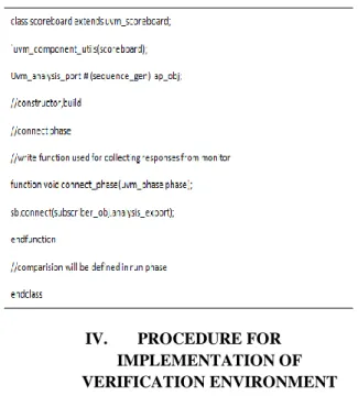
J. Scoreboard:
It is used for checking responses from DUT and comparing with golden reference or transfer functions output.
IV. PROCEDURE FOR IMPLEMENTATION OF VERIFICATION ENVIRONMENT
In industry level, Verification Process starts with Test plan and Verification Plan because of its complexity in doing verification task.
The test plan and Verification plan should be prepared for Vector Processor before starting implementation of Verification Environment. Test plan tells about list of test cases, stimuli can be passed to verify a specific design and error messages can be produced by DUV (Design under Verification) for specific input.
Verification plan consist of verification structure for DUV that how can be verified using components, whether the components can be reusable? etc. The Verification Environment for Vector Processor Engine as showed below.
Figure 4-1: UVM Environment
The goal of the Vector Processor verification has to verify an entire design functionality (Instruction set,
Control flow), interfaces and memory module up to maximum limit with high range of stimuli. It has been verified at maximum extent by using golden reference for DUV (Design under Verification) and simulates DUT and golden reference by passing same stimuli and checked the functionality by taking results from both golden reference and design. The bugs are reported to design team and the design team resolved the errors. MDP (Multi data path processor which is a vector processor) has been verified as a part of my M. Tech Project.
V. SIMULATION & RESULTS
A. Simulation:
VCS by Synopsys has been used for simulation purpose. In simulation process, “flist” plays as main file for compiling all modules present in verification process. In “flist” all files should be mentioned according to hierarchy and path should be mentioned on top of the “flist”. The commands for compile documents are “vcs –sverilog –f flist –debug” for debug purpose and then following command for output is “./simv –gui” .
B. Results:
Results have been collected are log files that which particular test has been passed or failed.
Those are
1. Test has been passed 2. Test has been failed Reports are as showed below:
Test has been failed:
Log report for VADDRNDCLIP:
Chronologic VCS simulator copyright 1991-2013
Contains Synopsys proprietary information.
Compiler version H-2013.06-SP1; Runtime version H-2013.06-SP1; May 23 12:07
2015
Execution in import function *********Testing VADDRNDCLIP instruction*****************
*********Testing addition in 32 bit mode********************
Error at 1: f984b8a9 ab1231a9 Error at 2: b043e5dd 1243e5dd Error at 3: 4cb4c917 321ac9b7 Error at 4: 184cb7d7 ab21e7e1 Error at 5: d2986098 12ab2021 Error at 6: c210f432 121aea46 Error at 7: f4f7f2a2 23abefa2 Error at 8: 25ab58f5 1aae21e1
**********VADDRNDCLIP TEST was
completed**************************
$finish called from file
"./hw/mdp_if_tbsv_latest.sv", line 291.
$finish at simulation time 397760000000
V C S S i m u l a t i o n R e p o r t
Time: 397760000000 ps
CPU Time: 3.420 seconds; Data structure size: 1.7Mb
Thu May 23 12:07:58 2015
Test has been passed:
Log report for VADDRNDCLIP:
Chronologic VCS simulator copyright 1991-2013
Contains Synopsys proprietary information.
Compiler version H-2013.06-SP1; Runtime version H-2013.06-SP1; May 23 12:07
2015
Execution in import function
***********testing VADDRNDCLIP instruction*******************
***********Testing addition in 32 bit mode************************* ***********Addition test passed in 32 bit mode**********************
***********VADDRNDCLIP TEST was completed***********************
C. Test Bench Wave Forms:
These are sample Test Bench wave form windows used for debugging purpose. In this way when we found error in functional verification wave forms will
be helpful to debug the test case step by step and helps in detecting error.
Wave Form 5-1: Input Stimuli
Wave Form 5-2: Execution Flow of Instruction
VI. Conclusion & Future Scope:
A. Conclusion:
The Verification Environment has been implemented for Vector Processor Engine (Multi Data Path processor (MDP)) in UVM. The MDP has been verified with maximum stimuli and covered all functionalities (Instruction set, Control flow, memory modules in MDP, and communication paths between Processor and peripherals) at maximum extent.
B. Future Scope:
The Environment can be reusable when new Methodology will be adopted and it can be useful for migrating to automation level.
References: [1] https://verificationacademy.com [2] www.duolos.com [3] www.asicworld.com [4] www.testbench.com [5] www.verilab.com/blog/2012/09/thoughts-on- verification-a-`fresh`-llok-at-uvm-part-1-of-2/
[6] Hans van der Schoot, Functional Coverage, SJ
SNUG, 2007
[7] Chris spear, System Verilog for Verification, 2nd
ed., SPRINGER, chapter9, functional Coverage
Author’s Profile:
Alluri Rama Devi received her
B.Tech degree in2011 from Sree Devi Women’s Engg. College, TS, India. She is currently working towards post-graduation degree in the department of Electronics and Communication engineering in CMR College of Engg & Technology, TS, India. Her research interest is in embedded systems and digital signal processing.
P.Raveendra Babu received his
post-graduation degree in the stream of Digital Systems & Computer Electronics and currently he is working as Associate Professor towards PhD in the department of Electronics and Communication Engineering in CMR College of Engg & Technology, TS, India with an experience of 13 years in teaching. His Research interests include Micro Electronics & VLSI,Antennas.
Anil santi received his post-graduation degree in the Department of Electronics and Communication and currently he is
working as Assistant Professor in the department of Electronics and Communication Engineering in CMR College of Engg & Technology, TS, India with an experience of 1.5 years in teaching. His Research interests include Communication and Electronics.