A Flexible and Secure Deployment Framework for
Distributed Applications
Alan Dearle, Graham Kirby, Andrew McCarthyand Juan Carlos Diaz y Carballo
School of Computer Science, University of St Andrews, North Haugh, St Andrews, Fife KY16 9SS, Scotland
{al, graham, ajm, jcd}@dcs.st-and.ac.uk
Abstract. This paper describes an implemented system that is designed to sup-port the deployment of applications offering distributed services, comprising a number of distributed components. This is achieved by creating high level placement and topology descriptions that drive tools to deploy applications consisting of components running on multiple hosts. The system addresses is-sues of heterogeneity by providing abstractions over host-specific attributes yielding a homogeneous run-time environment into which components may be deployed. The run-time environments provide secure binding mechanisms that permit deployed components to bind to stored data and services on the hosts on which they are running.
1 Introduction
This paper describes an implemented system that is designed to support the deploy-ment of applications offering distributed services, comprising a number of distributed components. A number of requirements for flexible service deployment may be iden-tified, including:
• an architectural description of software components, the hosts on which they are to execute, and the interconnections between them [1]
• the ability to enact the architectural description to obtain a running deployment consisting of the specified set of components—requiring:
the ability to install and execute code on remote hosts
a security mechanism to prevent malicious parties from deploying and execut-ing harmful agents, and deployed components from interferexecut-ing with each other, either accidentally or maliciously
• support for component implementation using standard programming languages and appropriate programming models
• the ability for components to interface with off-the-shelf (COTS) components already deployed
placement of both code and data by authorised users, in a secure and simple manner. They support a model of global computation in which objects have global identity, and the programmer may define the physical domain in which code is executed. Thin servers do not replace existing hosts, but are instead used to complement existing infrastructure to increase its usability and effectiveness. Indeed, thin servers can be co-hosted on conventional servers, and the services offered by them may be indistin-guishable from conventional services.
In order to permit deployed components to be assembled into appropriate topolo-gies and communicate with each other, the components must exhibit some degree of interface standardisation. In the implementation described here, communication is via asynchronous channels that may be dynamically rebound to arbitrary components either by the components themselves or by suitably privileged external parties.
All software applications are subject to evolutionary pressure. In order to respond to these pressures, it may be necessary to adapt parameters of the deployed services, including, but not limited to, the placement of components and data on machines and the components’ interconnection topology.
This paper describes a framework that permits distributed services to be described, deployed and evolved in distributed contexts. It provides binding mechanisms that permit components to bind to local code, data and processes, including inter-node, inter-component bindings. When combined, these provide a run-time environment within which a deployed application may evolve. The framework contributes to the state of the art in six areas, providing:
1. mechanisms for deploying code and data in a distributed environment
2. abstractions over node specific attributes yielding a homogeneous run-time envi-ronment for deployed components
3. safe binding mechanisms so that deployed components can bind to stored data and services on the nodes on which they are running
4. mechanisms for describing and deploying distributed applications consisting of components running on multiple nodes
5. the ability to evolve the topology of deployed applications and components 6. security mechanisms that permit a wide range of policies to be implemented
rang-ing from liberal to draconian
The deployment framework described here is based on an enabling infrastructure called Cingal1 [2, 3]. Cingal itself addresses points 1-3 above, while the deployment infrastructure adds support for points 4-6.
2 The Cingal Computational Model
Cingal supports a conceptually simple computational model in which each thin server provides the following:
• a port to which a bundle of code and data may be sent for execution • authentication mechanisms, preventing unauthorised code from executing
• a content addressable store
• symbolic name binders for data and processes
• an extensible collection of execution environments called machines
• channel-based asynchronous inter-machine communication
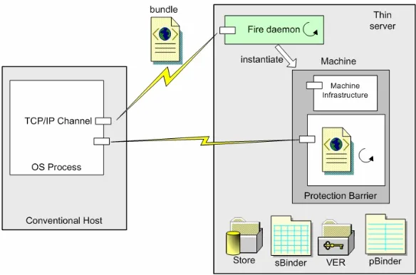
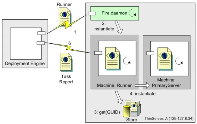
[image:3.595.151.443.284.477.2]• a capability system controlling access to stored data, machines and bindings. The computational model is illustrated in Fig 1, which shows two hosts: a conven-tional host that might be running Windows or MacOS, and a thin server running the Cingal infrastructure. In order to execute code on a thin server, an OS process on the conventional host sends a bundle of code and data to the thin server where it is re-ceived by a daemon known as the fire daemon.
Fig 1: Cingal computational model
The fire daemon authenticates the bundle using mechanisms described later and, provided that it is authenticated, the bundle is fired. This causes a new operating system process to be created, which executes the code in the bundle. This process, which we term a machine, contains the code in the bundle and machine infrastructure containing code and data structures provided by the thin server. The infrastructure provides mechanisms to allow executing bundles to access the services provided by thin servers, to interface with the protection mechanisms, and to permit inter-machine communication channels to be established. The infrastructure may be invoked from other processes via an interface called the machine channel and from the executing bundle via an API (called the machine API) provided to the bundle when it is initial-ised2.
The thin server infrastructure includes a number of services that may be invoked from bundles executing within machines. These are the store, store binder, process binder and valid entity repository (VER), providing storage, binding and certificate
storage respectively. A running bundle’s interactions with these services are restricted via a capability protection scheme mediated via library code in the infrastructure.
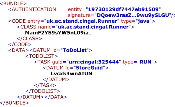
The bundle is the only user-level entity that may be executed in Cingal. It is pas-sive, consisting of a closure of code and data and a set of bindings naming the data. In the current implementation bundles are XML-encoded, as illustrated in Fig 2. Each bundle carries an authentication element with attributes entity and signature. The entity identifies the bundle using a globally unique identifier (GUID) implemented via an MD5 key. The signature is used by the security infrastructure. In the current implementation, code may be either MIME-encoded Java classes or JavaScript source. In principle, any programming language could be used for encoding compo-nents, provided that the appropriate run-time support was provided. When a bundle is fired, execution begins at the entry point specified by the entry attribute of the code element, which specifies code that implements a standard interface. The data section of a bundle, known as its payload, comprises data with each datum having a unique id attribute. In the example the bundle carries one datum named ToDoList. It is com-mon for bundles to carry other bundles in their payload, in order to install bundles in the store or fire them in other machines.
Subject to the capability protection scheme, bundles may carry out any arbitrary computation that they are encoded to perform, including the provision of network services.
<BUNDLE>
<AUTHENTICATION entity="19730129df7447eb91509" signature="DQoew3rasZ…9wu9ySLGU"/> <CODE entry="uk.ac.stand.cingal.Runner" type="java">
<CLASS name="uk.ac.stand.cingal.Runner">
MamF2YS9sYW5nL09ia…
</CLASS> </CODE>
<DATA><DATUM id="ToDoList"> <TODOLIST>
<TASK guid="urn:cingal:325444" type="RUN"> <DATUM id="StoreGuid">
Lvcxk3wnAIUN…
[image:4.595.126.415.387.564.2]</DATUM> </TASK> </TODOLIST> </DATUM></DATA> </BUNDLE>
Fig 2: An example bundle
The store provided by each machine is a collection of passive data and supports the storage of arbitrary bundles. So that a bundle may be retrieved, a key in the form of a GUID is returned by the store on its insertion. If that key is later presented, the origi-nal bundle is returned. Stores do not support any update operations. Where the effects of update are required by an application, these may be obtained using binders.
stan-dard put, remove and get operations.
Cingal supports asynchronous message-oriented inter-machine communication. All communication is via channels that support conventional read and write operations. Each machine has associated with it a minimum of two channels as shown in Fig 1. The first is called the machine channel and is used to communicate with the machine infrastructure. The second is called the default channel and is used to communicate with the bundle running within the machine. An interface to the default channel is returned to its progenitor whenever a bundle is fired. The fired bundle may access the default channel via the machine API.
The channel established between a bundle and its progenitor is normally used for diagnostics and the passing of parameters. In order to accommodate change and dy-namic deployment, the Cingal computational model supports named channels be-tween entities. This idea stems from Milner’s π-calculus [4]. Using named channels, individual executing bundles are isolated from the specifics of what components are connected to them. This isolation permits channels to be connected, disconnected and reconnected independently of the running program. Connections may be manipulated by the connected bundles or by third parties. This ability is necessary for the orches-tration, evolution and autonomic management of deployed applications [5].
Within the machine infrastructure a component called the connection manager is responsible for the management of named channels. It maintains an associative map-ping of names to channels. This mapmap-ping may be manipulated by other machines via the machine’s machine port and by the bundle being executed via the machine API.
The model described thus far is a perfect virus propagation mechanism. Code may be executed on remote nodes and that code may create new processes, update the store, create name bindings and fire bundles on other thin servers. Cingal implements a two-level protection system. The first level of security restriction is on the firing of bundles. A conventional Unix or Windows style security model is not appropriate for thin servers, which do not have users in the conventional sense. Instead, security is achieved by means of digital signatures and certificates. Each thin server maintains a list of trusted entities, each associated with a security certificate. Entities might corre-spond to organisations, humans or other thin servers. This data structure is maintained by a process called the Valid Entity Repository (VER).
Bundles presented for firing from outwith a thin server must be signed by a valid entity stored in the VER. The VER maintains an associative data structure indexed by the entity id and mapping to a tuple including certificates and rights. Operations are provided for adding and removing entities from the repository. Of course these opera-tions are subject to the second protection mechanism, which is capability-based. An example of a signed bundle was shown in Fig 2.
The entity attribute of the authentication element represents the name of an entity in the VER of the thin server on which the bundle is being fired and the signature is the signed body of the bundle’s code payload. The thin server deployment infrastruc-ture for deploying bundles from conventional machines provides programmers with methods that simplify the signing of bundles.
pos-sible for bundles to be totally isolated, giving the illusion that each is the only entity running on a thin server. Conversely, bundles may share resources when appropriate.
To address these needs, the second protection mechanism provided by thin servers is capability-based. In addition to the signatures stored in the VER, thin servers store segregated capabilities for entities stored in the store, sBinder, pBinder and the VER itself. Whenever a running bundle attempts an operation, the capabilities stored in the VER associated with the entity that invoked the operation are checked. The operation only proceeds if the entity holds sufficient privilege.
3 Application Deployment
The Cingal system provides the infrastructure for deploying components on arbitrary suitably enabled hosts. However, additional infrastructure is needed to a) describe distributed architectures, and b) deploy components from the descriptions. This infra-structure comprises a description language, a deployment engine, and various mobile code documents and tools.
The description language is an XML schema, instances of which are Deployment Description Documents (DDDs). Each DDD contains an architectural description of an application, comprising a set of autonomous software components, the hosts on which they are to execute, and the interconnections between them.
The deployment engine takes a DDD as input and deploys the components de-scribed in it on the appropriate hosts. These components are pushed to the hosts as Cingal bundles; every participating host is Cingal-enabled. The deployment engine also pushes various tools to the hosts to carry out local deployment tasks in situ, prin-cipally installing and initialising the components, and configuring the interconnection topology of the deployed application. These tools are also transferred as bundles.
The data element of a tool bundle includes a control document called a to-do list. This contains a set of tasks to be attempted by the tool when it arrives and is fired on the destination thin server. When the tool completes these tasks, it sends a task report document back to the deployment engine, listing the outcomes of each task and any other associated information. Examples of associated information might include the GUIDs of stored bundles, or the names of channels and machines.
The three primary tools are installers, runners and wirers. An installer installs an arbitrary number of payload bundles into the store of the destination thin server. A runner starts the execution of a number of bundles previously installed in the store. A wirer is responsible for making concrete connections between pairs of components using the named channel mechanism.
Under control of these tools, each application component on a thin server moves between the following states:
• installed: when the bundle has been installed into the store
• running: when the bundle has been fired and started computation; any reads or writes on named channels will block since they are not connected
During initial deployment of an application the constituent components move from installed to running to wired. During subsequent evolution the components may move from wired to running to wired again, in cases where only the interconnection topology needs to change, or from wired to running to installed to running to wired again, in cases where components need to be moved to different hosts in the network. Each instance of a deployment tool is pushed to the appropriate host as a bundle containing a fixed code element depending on its type (i.e. installer, runner or wirer), and a data element configured to its particular role. Thus every installer bundle con-tains the same generic installer implementation (currently a Java class), which is spe-cialised by the bundle payload—and similarly for runners and wirers.
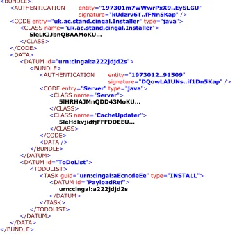
The example installer bundle shown in Fig 3 contains the installer code: the class uk.ac.stand.cingal.Installer. The payload carries another bundle, itself containing the classes Server and CacheUpdater, and a to-do list specifying that that bundle (identi-fied by the id attribute value "urn:cingal:a222jdjd2s") should be installed. <BUNDLE>
<AUTHENTICATION entity="197301m7wWwrPxX9..EySLGU" signature="kUdzrv6T..fFNn5Kap" /> <CODEentry="uk.ac.stand.cingal.Installer" type="java">
<CLASSname="uk.ac.stand.cingal.Installer">
5leLKJJbnQBAAMoKU…
</CLASS> </CODE> <DATA>
<DATUMid="urn:cingal:a222jdjd2s"> <BUNDLE>
<AUTHENTICATION entity="1973012..91509"
signature="DQowLAIUNs..if1Dn5Kap" /> <CODEentry="Server" type="java">
<CLASSname="Server">
5lHRHAJMnQDD43MoKU…
</CLASS>
<CLASSname="CacheUpdater">
5leHdkvjidfjFFFDDEEU…
</CLASS> </CODE> <DATA /> </BUNDLE> </DATUM>
<DATUMid="ToDoList"> <TODOLIST>
<TASKguid="urn:cingal:aEcncdeEe" type="INSTALL"> <DATUMid="PayloadRef">
urn:cingal:a222jdjd2s
[image:7.595.125.463.321.662.2]</DATUM> </TASK> </TODOLIST> </DATUM> </DATA> </BUNDLE>
Examples of runners and wirers are shown in Figs 2 and 6 respectively.
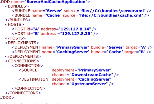
A DDD is a static description of a distributed graph of components; an example is shown in Fig 4. It specifies the locations of the required components (bundles), the hosts available, the mapping of components to hosts (deployments) and the connec-tions between named channel pairs.
<DDDname="ServerAndCacheApplication"> <BUNDLES>
<BUNDLEname="Server" source="file://C:\bundles\server.xml" /> <BUNDLEname="Cache" source="file://C:\bundles\cache.xml" /> </BUNDLES>
<HOSTS>
<HOSTid="A" address="129.127.8.34" /> <HOSTid="B" address ="129.127.8.35" /> </HOSTS>
<DEPLOYMENTS>
<DEPLOYMENTname="PrimaryServer" bundle="Server" target="A" /> <DEPLOYMENTname="CachingServer" bundle="Cache" target="B" /> </DEPLOYMENTS>
<CONNECTIONS> <CONNECTION>
<SOURCE deployment="PrimaryServer" channel="DownstreamCache" /> <DESTINATION deployment="CachingServer"
channel="UpstreamServer" /> </CONNECTION>
[image:8.595.129.453.214.434.2]</CONNECTIONS> </DDD>
Fig 4: A Deployment Description Document
The first phase of application deployment involves installation of component bundles on appropriate hosts. The deployment engine reads a DDD and retrieves the specified bundles from their given locations (which may be within a local file-based component catalogue or elsewhere on the network). It then configures an installer bundle for each host by generating an appropriate to-do list. These installers are fired as illustrated in Fig 1 on the participating thin servers throughout the network. The action of each executing installer bundle on arrival is to extract its payload component bundles and add them to the local store. It then sends a task report back to the deployment engine listing the resulting store keys of the installed bundles, and terminates.
thin server A. The runner retrieves the Server bundle from A’s store and fires it in a new machine, and returns a task report to the deployment engine.
Fig 5: The running process
The final phase of application deployment involves connecting (termed wiring) the named channels on the running bundles to assemble the global application topology. The deployment engine configures a wirer bundle for each connection, by generating an appropriate to-do list. The wiring process will begin on one of the thin servers selected arbitrarily. Each wirer created is configured with a to-do list describing: 1. The connector for each machine—this contains the IP address of the machine and
the machine and resource ports.
2. The name used by the executing bundle to reference the channel in both machines (this may be different for each machine).
Fig 6 shows an example wirer bundle for thin server A, which is (arbitrarily) chosen as the initiating thin server for the connection between the named channels Down-streamCache and UpstreamServer. Note that this bundle cannot be generated by the deployment engine until it has received the task reports from the runner bundles, since those contain the necessary port numbers.
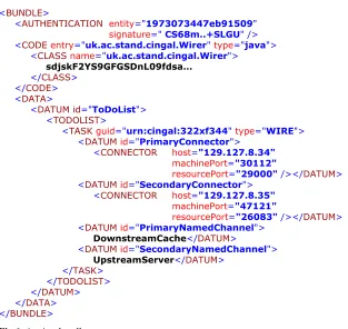
<BUNDLE>
<AUTHENTICATION entity="1973073447eb91509" signature=" CS68m..+SLGU" /> <CODE entry="uk.ac.stand.cingal.Wirer" type="java">
<CLASS name="uk.ac.stand.cingal.Wirer">
sdjskF2YS9GFGSDnL09fdsa…
</CLASS> </CODE>
<DATA>
<DATUM id="ToDoList"> <TODOLIST>
<TASK guid="urn:cingal:322xf344" type="WIRE"> <DATUM id="PrimaryConnector">
<CONNECTOR host="129.127.8.34" machinePort="30112"
resourcePort="29000" /></DATUM> <DATUM id="SecondaryConnector">
<CONNECTOR host="129.127.8.35" machinePort="47121"
resourcePort="26083" /></DATUM> <DATUM id="PrimaryNamedChannel">
DownstreamCache</DATUM>
<DATUM id="SecondaryNamedChannel">
UpstreamServer</DATUM> </TASK>
[image:10.595.126.439.141.437.2]</TODOLIST> </DATUM> </DATA> </BUNDLE> Fig 6: A wirer bundle
Fig 7: The wiring process
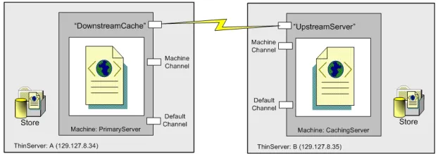
Once all the wirers have completed their (possibly parallel) computation, the wiring process is complete and the named channels are connected as shown in Fig 8. This completes the deployment of the distributed application.
Fig 8: Result of wiring process
4 Related Work
[image:11.595.142.453.381.491.2]can be a producer and/or a consumer, and all its associated wires are conceptually equivalent. Cingal allows any number of symbolically named ports to be associated with a bundle, and the programmer may treat these differently. However, the two schemes have equivalent modelling power. Finally, Cingal is more flexible with re-gards to initial provisioning: its ubiquitous fire service allows bundles to be pushed to a new node from a remote management agent without any intervention required lo-cally on the node. Initial provisioning in OSGi involves pull from a new node, which must be initialised somehow with an address from which to pull the code. The ad-dress may be provided by various means such as direct user intervention, factory installation, reading from a smartcard, etc.
A number of languages have been developed to describe software architectures, including [7-9]. Typical of these is Acme [1], which is intended to fulfil three roles: to provide an architectural interchange format for design tools, to provide a founda-tion for the design of new tools and to support architectural modelling. The Acme language supports the description of components joined via connectors, which pro-vide a variety of communication styles. Components and connectors may be anno-tated with properties that specify attributes such as source files and degrees of concur-rency, etc. Acme also supports a logical formalism based on relations and constraints, which permits computational or run-time behaviour to be associated with the descrip-tion of architectures. Acme does not support the deployment of systems from the architectural descriptions, nor does it encompass physical computation resources.
The ArchWare ADL [10] is based on higher-order π-calculus, and is aimed at specifying active architectures, in which the architectural description of an applica-tion evolves in lock-step with the applicaapplica-tion itself. The language supports a reversi-ble compose operator that allows components to be assembled from other compo-nents, and later decomposed and recomposed to permit evolution. Decomposition operates at a fine-grain, and it is possible to decompose a component into constituent parts without losing encapsulated state. This is achieved using hyper-code [11], which provides a reified form for both code and data. In comparison, the ArchWare ADL focuses on software architecture and does not address physical deployment.
The idea of installing components using agents has its roots in a number of places. Java Servlets were initially developed within Sun Labs with the express purpose of freeing the restrictions of a fixed repertoire service, allowing the client to modify the behaviour of the server. However, as they moved into a commercial product domain, this flexibility was removed as it was deemed to compromise the security of the un-derlying traditional operating system [12]. The Infospheres project from Caltech [13] has some overlap with the system described here. They propose a system of distrib-uted Java processes (dapplets), which can be connected using asynchronous message passing.
no-tion of distributed components, communicano-tion channels nor high-level architectural descriptions.
5 Conclusions
At the start of this paper six claims were made about our deployment architecture3. In conclusion, these claims are critically re-examined.
Claim 1: The Cingal infrastructure permits bundles to be deployed in arbitrary geographic locations from conventional machines. Bundles may perform arbitrary computation and offer arbitrary network services.
Claim 2: The runtime infrastructure provided by Cingal thin servers abstracts over host-specific differences yielding a homogeneous run-time environment for deployed components.
Claim 3: The store and binder provided by thin servers support content-addressed storage, which permits code and data to be stored with no possibility of ambiguous retrieval. The binder permits objects to be symbolically named to facilitate the re-trieval of components whose content keys are not known. The binder also provides an evolution point supporting update of component mappings.
Claim 4: Deployment Description Documents support the specification of distrib-uted architectures. The deployment engine technology combined with the thin server infrastructure permits these distributed deployments to be realised into running in-stances of component based architectures. The process of deployment from specifica-tion through to having a connected collecspecifica-tion of running components on distributed hosts is totally automated.
Claim 5: A number of novel evolution mechanisms are provided by the architec-ture. Firstly, the architecture supports the ability to remotely update components. Secondly flexible binding between components is made possible thorough the binder and store interfaces. Most importantly, distributed architectures may be re-arranged by unbinding and reconnecting named channels within machines running on thin servers.
Claim 6: The two security mechanisms provided by Cingal prevent unauthorised entities from firing bundles on hosts on which they do not have privilege. The owner-ship model which makes uses of standard cryptographic certificate techniques is well suited to distributed deployment. Tools (not described here) that operate in a similar manner to the deployment tool are provided for managing entity privileges and updat-ing collections of machines. The capability protection system provided within Cupdat-ingal thin servers prevents bundles being used for malicious or unintentional abuse of the thin server infrastructure.
3The current implementation may be downloaded from
6 Future Work
In the future we propose to expand the system in two primary ways. Firstly we would like to make the specification of distributed components more declarative. To this end we are currently investigating the use of constraint based specification languages. It is our intention to construct higher level specifications and a set of tools to support them and compile these specifications down to DDD documents. Secondly, we are investi-gating how evolution can be specified at the DDD level. Since we use DDDs to spec-ify deployments, it seems natural to have high-level descriptions of evolution and automatically generate bundles to enact the necessary changes. Another interesting line of investigation is the use of a higher level specification of architectural intent from which DDDs may be generated. We are currently investigating the use of con-straint based specification languages for this purpose [5]. We believe that this ap-proach may be combined with the infrastructure described in this paper to yield sys-tems that are capable of autonomic evolution in the face of perturbations such as host and link failure, temporary bandwidth problems, etc. We postulate that it will be feasible to implement an autonomic manager that will automatically evolve the de-ployed application to maintain the constraints while it is in operation.
7 Acknowledgements
This work is supported by EPSRC grants GR/M78403 “Supporting Internet Compu-tation in Arbitrary Geographical Locations”, GR/R51872 “Reflective Application Framework for Distributed Architectures” and by EC Framework V IST-2001-32360 “ArchWare: Architecting Evolvable Software”.
The authors thank Richard Connor for his invaluable input to the Cingal project, on which he was a principal investigator, and Ron Morrison who read early drafts of this paper.
8 References
1. Garlan D., Monroe R., Wile D. ACME: An Architecture Description Interchange Lan-guage. In: Proc. Conference of the Centre for Advanced Studies on Collaborative Re-search (CASCON'97), Toronto, Canada, 1997, pp 169-183
2. Diaz y Carballo J.C., Dearle A., Connor R.C.H. Thin Servers - An Architecture to Sup-port Arbitrary Placement of Computation in the Internet. In: Proc. 4th International Con-ference on Enterprise Information Systems (ICEIS 2002), Ciudad Real, Spain, 2002, pp 1080-1085
3. Dearle A., Connor R.C.H., Diaz y Carballo J.C., Neely S. Computation in Geographi-cally Appropriate Locations (CINGAL). EPSRC, 2002. http://www-systems.dcs.st-and.ac.uk/cingal/
5. Dearle A., Kirby G.N.C., McCarthy A. A Framework for Constraint-Based Deployment and Autonomic Management of Distributed Applications (Extended Abstract). To Ap-pear: Proc. International Conference on Autonomic Computing (ICAC-04), New York, USA, 2004
6. OSGi Service Platform Release 3. Open Services Gateway Initiative, 2003
7. Garlan D., Allen R., Ockerbloom J. Exploiting Style in Architectural Design Environ-ments. In: Proc. 2nd ACM SIGSOFT Symposium on Foundations of Software Engineer-ing, New Orleans, Louisiana, USA, 1994, pp 175-188
8. Moriconi M., Qian X., Riemenschneider R.A. Correct Architecture Refinement. IEEE Transactions on Software Engineering 1995; 21,4:356-372
9. Shaw M., DeLine R., Klein D.V., Ross T.L., Young D.M., Zelesnik G. Abstractions for Software Architecture and Tools to Support Them. IEEE Transactions on Software Engi-neering 1995; 21,4:314-335
10. Morrison R., Kirby G.N.C., Balasubramaniam D., Mickan K., Oquendo F., Cîmpan S., Warboys B.C., Snowdon B., Greenwood R.M. Constructing Active Architectures in the ArchWare ADL. University of St Andrews Report CS/03/3, 2003
11. Kirby G.N.C. Reflection and Hyper-Programming in Persistent Programming Systems. PhD thesis, University of University of St Andrews, 1992
12. Jordan M. Java Servlets Discussion. Personal Communication, 1998
13. Chandy K.M., Rifkin A., Sivilotti P.A.G., Mandelson J., Richardson M., Tanaka W., Weisman L. A World-Wide Distributed System Using Java and the Internet. In: Proc. In-ternational Symposium on High Performance Distributed Computing (HPDC-5), Syra-cuse, New York, 1996