ISSN Online: 1947-394X ISSN Print: 1947-3931
DOI: 10.4236/eng.2018.1010051 Oct. 23, 2018 704 Engineering
The Implementation and Lateral Control
Optimization of a UAV Based on Phase Lead
Compensator and Signal Constraint Controller
Adil Loya
1, Muhammad Duraid
1, Kamran Maqsood
2, Rehan Rasheed Khan
31Department of Mechatronics Engineering, PAF Karachi Institute of Economics and Technology, Karachi, Pakistan 2School of Engineering and Informatics, Sussex University, Brighton, UK
3Department of Avionics Engineering, PAF Karachi Institute of Economics and Technology, Karachi, Pakistan
Abstract
Unmanned Aero Vehicles (UAV) has become a useful entity for quite a good number of industries and facilities. It is an agile, cost effective and reliable solution for communication, defense, security, delivery, surveillance and sur-veying etc. However, their reliability is dependent on the resilient and stabi-lizes performance based on control systems embedded behind the body. Therefore, the UAV is majorly dependent upon controller design and the re-quirement of particular performance parameters. Nevertheless, in modern technologies there is always a room for improvement. In the similar manner a UAV lateral control system was implemented and researched in this study, which has been optimized using Proportional, Integral and Derivative (PID) controller, phase lead compensator and signal constraint controller. The sig-nificance of this study is the optimization of the existing UAV controller plant for improving lateral performance and stability. With this UAV com-munity will benefit from designing robust controls using the optimized me-thod utilized in this paper and moreover this will provide sophisticated con-trol to operate in unpredictable environments. It is observed that results ob-tained for optimized lateral control dynamics using phase lead compensator (PLC) are efficacious than the simple PID feedback gains. However, for opti-mizing unwanted signals of lateral velocity, yaw rate, and yaw angle modes, PLC were integrated with PID to achieve dynamical stability.
Keywords
Lateral Control, Simulink, PID Signal Constraining, Phase Lead Compensators, Unmanned Aero Vehicle
How to cite this paper: Loya, A., Duraid, M., Maqsood, K. and Khan, R.R. (2018) The Implementation and Lateral Control Optimization of a UAV Based on Phase Lead Compensator and Signal Constraint Controller. Engineering, 10, 704-729.
https://doi.org/10.4236/eng.2018.1010051 Received: September 5, 2018
Accepted: October 20, 2018 Published: October 23, 2018
Copyright © 2018 by authors and Scientific Research Publishing Inc. This work is licensed under the Creative Commons Attribution International License (CC BY 4.0).
http://creativecommons.org/licenses/by/4.0/
DOI: 10.4236/eng.2018.1010051 705 Engineering
1. Introduction
Sheiba-DOI: 10.4236/eng.2018.1010051 706 Engineering ni investigated that by applying PID controllers on lateral and longitudinal sta-bility optimizes the performance of the aircraft dynamics. PID controller effica-ciously improved the settling time and over shoot harmonics were undermined, this demonstrates that significant amount of controllability has been achieved
[15].
Controlling UAVs has become a hot topic for last couple of years. So, the term controllability is the property that determines the performance, that how much a system is reliable and stable for different input parameters. Actual working of PID is to shift poles of the system from right half plane to left half plane in root locus plot using PID gain scheduling, by doing so system becomes stable. More-over, Muluken Regas in his research used PID with neural network controller giving insight into optimization of PID using neural networks. They compared UAV’s pitch altitude control parameters developed by each controlling tech-niques. Thus, they concluded that for hardware implementation of any UAV model with smooth alteration to achieve better maneuverability, PID is a prime candidate for the designing of optimized controller [16].
Keeping in mind the researches related with PID optimization and checking out the literature; it is pretty much applicable that there is still room for im-provement. Hence in this research efforts have been plugged to optimize PID using signal constraining and Phase Lead Compensator (PLC).
Nevertheless, in some cases of controlling lateral mode PID controller is not feasible enough to give steady state response, therefore, a good practice in this case is to implement a phase lead compensator. The PLCs are generally used for improving the transient response of a dynamic system. This controller adds up positive contribution in the sum of angles in the angle measurement. It helps in moving the close loop poles towards the negative half of the s-plane, due to which stability and speed of the system response is optimized. This technique is proven to be fruitful in one of the studies investigated for pitch and altitude control by Ahsan et al. [17]. They investigated that by using a PLC, transient re-sponse characteristics were improved as compared to PID controller. However, the PLC takes longer rise time for his case, but offers negligible overshoots.
2. Plant Description
An initial design for this proposed model of UAV was created using XFLR5, a freeware software used for designing and modelling flight dynamics of UAVs. XFLR5 Plane designing module lets one to easily design, as well as, visualize the input variables while changing different design parameters of the aircraft body
DOI: 10.4236/eng.2018.1010051 707 Engineering plant is necessary for the practical design of an UAV. In addition to this, the mathematical model is a fundamental plant for designing of an open loop sys-tem. Nevertheless, plant designing further requires a feedback response, for which a closed loop system is integrated using PID control technique. The PID controller was implemented to stabilize the response of the control surfaces by decreasing the overshoot and optimizing the settling time to meet the monoton-ic decay.
The longitudinal equations for the plant are derived by applying laws of new-ton for the motion of a rigid body under the effect of constant external forces and moments summation to the angular acceleration. These are the following assumptions taken for simulating proposed model equations [19].
Assumptions taken; the geometrical shape parameters are jotted in Table 1, moreover some of the configuration, stability and control parameters were ob-tained from author’s previous study [18]. Stability analysis of UAV model re-quires, aerodynamic analysis of complete UAV plant to measure its different stability coefficients. The proposed model was analyzed using Vortex lattice me-thod (VLM), while coefficient of X-Center of Gravity and Z-Center of Gravity was set at 0.09 m and 0.003 m respectively. Moreover, proposed plant was expe-rienced with 35 m/s velocity and density for the physical attributes were settled at 1.225 Kg/m3, meanwhile the viscosity level was 1.461e-5 m2/s and Dirichlet boundary were set for analysis.
1) The Earth is non-rotating.
2) Unmanned aero vehicle is supposed to be a constant mass rigid body.
3. Working
MATLAB/Simulink simulation is used to incorporate the proposed model, which was achieved by designing of UAV model on XFLR5. Stability and control derivatives were also obtained and calculated through XFLR5. These derivatives and parameters for transfer functions were plugged in the MATLAB prompt to generate the longitudinal and lateral matrix. The parameters used for designing the transfer function are given in Table 1; this enabled us to design the transfer function from its state space model. Moreover, the initial control outputs deter-mined using open loop system approach gave unstable response, obviously, sys-tem requires a feed-back response inherited with a certain controller to stabilize its response. While in this proposed study, PID was implemented for system re-sponse refinement and phase lead compensators were used for optimizing unst-able dynamics of certain inputs that were not easily controlled by PID. Likewise, Rudder and Aileron parameters obtained through PID controller demonstrated stable characteristics, but 2 parameters from the both groups were further stabi-lized through compensating gain technique. A schematic design shows the workflow of this research in Figure 1.
DOI: 10.4236/eng.2018.1010051 708 Engineering Figure 1. Schematic of the workflow that has been performed in this research.
Table 1. UAV design specifications [7].
Wing design
Span 1.3 m
Area 0.23 m
Mean aerodynamic chord 0.18 m
Fuselage
Maximum length 0.95 m
Maximum Take-off weight 12 Kg
Horizontal Tail
Span 0.12 m
Root chord 0.14 m
Tip chord 0.14 m
Sweep 18.43 deg
Dihedral 25 deg
Vertical Tail
Span 0.12 m
Root chord 0.14 m
Tip chord 0.06 m
Sweep 9.46 deg
Aerodynamic atmospheric properties
Gravity 9.8 m/s2
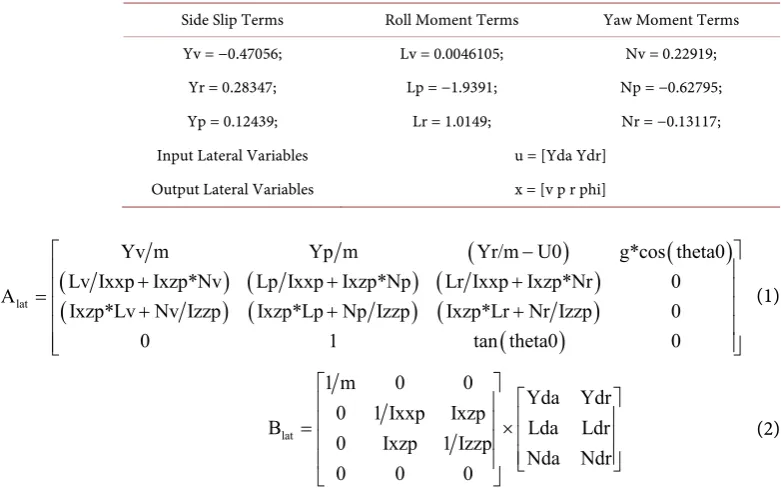
[image:5.595.164.536.300.738.2]DOI: 10.4236/eng.2018.1010051 709 Engineering Table 2. Lateral stability parameters.
Side Slip Terms Roll Moment Terms Yaw Moment Terms Yv = −0.47056; Lv = 0.0046105; Nv = 0.22919;
Yr = 0.28347; Lp = −1.9391; Np = −0.62795; Yp = 0.12439; Lr = 1.0149; Nr = −0.13117; Input Lateral Variables u = [Yda Ydr]
Output Lateral Variables x = [v p r phi]
(
)
(
)
(
) (
) (
)
(
) (
) (
)
(
)
lat
Yv m Yp m Yr/m U0 g*cos theta0
Lv Ixxp Ixzp*Nv Lp Ixxp Ixzp*Np Lr Ixxp Ixzp*Nr 0
A
Ixzp*Lv Nv Izzp Ixzp*Lp Np Izzp Ixzp*Lr Nr Izzp 0
0 1 tan theta0 0
− + + + = + + + (1) lat
1 m 0 0
Yda Ydr
0 1 Ixxp Ixzp
B Lda Ldr
0 Ixzp 1 Izzp
Nda Ndr
0 0 0
= × (2)
By using Equations (1) and (2) and Table 1 data, state space model for the lateral dynamics was established. This lateral plant was then divided into five lateral variables that x = [v p r phi psi]; where x is the output variable that con-sist of v which is “lateral velocity component”, p is “roll rate component”, r is “yaw rate component”, phi is “roll angle component”. Multiple Input and Mul-tiple Output (MIMO) system transfer function equations were designed out of these multi variable outputs (these equations are shown from Equations (3) to (12), where input variables controlling these equations were two i.e. one is for aileron input dependent represented by “Yda” and other one is rudder input dependent “Ydr”. Transfer functions acquired for state space model are given from Equations (3)-(12) in Table 3 and Table 4.
3.1. Plant Description When in Loop with PID
We can describe PID controller with following continuous S domain transfer function.
( )
ic p K d
G s P I D K K s
s
= + + = + + (13)
DOI: 10.4236/eng.2018.1010051 710 Engineering Table 3. UAV lateral dynamic transfer functions with respect to aileron input.
Terms Transfer Functions Equation Numbers
r v δ
3 2
4 3 2
0.672 596.4 4233 1451
6.899 8.475 39.67 5.853
s s s
s s s s
+ − −
+ + + − (3)
r p δ
3 2
4 3 2
431.5 164.8 2566
6.899 8.475 39.67 5.853
s s s
s s s s
− − −
+ + + − (4)
r r δ
3 2
4 3 2
17.05 0.56 0.0001768 718.3
6.899 8.475 39.67 5.853
s s s
s s s s
− − − −
+ + + − (5)
r φ δ
2
4 3 2
431.5 164.8 2566
6.899 8.475 39.67 5.853
s s
s s s s
− − −
+ + + − (6)
r ψ δ
3 2
5 4 3 2
17.05 0.56 0.0001768 718.3
6.899 8.475 39.67 5.853
s s s
s s s s s
− − − −
+ + + − (7)
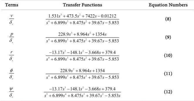
Table 4. UAV lateral dynamic transfer functions with respect to rudder input.
Terms Transfer Functions Equation Numbers
r v δ
3 2
4 3 2
1.531 473.5 7422 0.01212
6.899 8.475 39.67 5.853
s s s
s s s s
+ + −
+ + + − (8)
r p δ
3 2
4 3 2
228.9 8.964 1354
6.899 8.475 39.67 5.853
s s s
s s s s
+ +
+ + + − (9)
r r δ
3 2
4 3 2
13.17 148.1 3.668 379.4
6.899 8.475 39.67 5.853
s s s
s s s s
− − − +
+ + + − (10)
r φ δ
2
4 3 2
228.9 8.964 1354
6.899 8.475 39.67 5.853
s s
s s s s
+ +
+ + + − (11)
r ψ δ
3 2
5 4 3 2
13.17 148.1 3.668 379.4
6.899 8.475 39.67 5.853
s s s
s s s s s
− − − +
+ + + − (12)
control, integral controller is always used to decrease the error after this imple-mentation, tendency towards oscillations increases with the decrease in integral time. Moreover, integral coefficient minimizes the steady state error. However, derivative term is used to decrease the damping effect on closed loop response, initially damping increases with small increase of derivative time, however, with large derivative damping becomes minimal. In this proposed research root locus based PID controller is implemented for the lateral control, using lateral sub-model of a UAV.
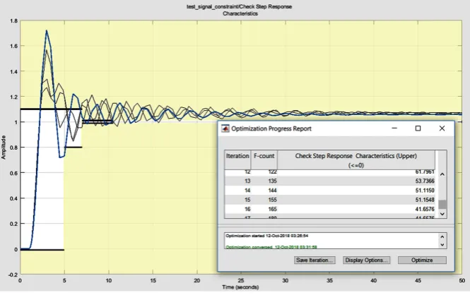
3.2. Plant Description When in Loop with Signal Constraining PID
[image:7.595.208.539.294.467.2]applica-DOI: 10.4236/eng.2018.1010051 711 Engineering tions. Therefore, due to fast computing invention, it is now possible to use SCPC in dynamically fast process like civil air-vehicles. In this proposed model objec-tive of this computational signal constraining is to attain future predictions for optimized control of different parameters sequence. Hence, predicted outputs could be used to drive UAV with more optimized and stable way. Moreover, to predict future process outputs for the control variables, this topology explicitly uses mathematical model [20]. A signal constrained optimization technique general output overview is shown in Figure 2.
3.3. Plant Description When in Loop with Lead Compensator
General equation for frequency domain description for phase lead compensator is given by Equation (4) [17];
( )
(
(
0)
)
0
c c
s z
G s K
s p
− =
− (14)
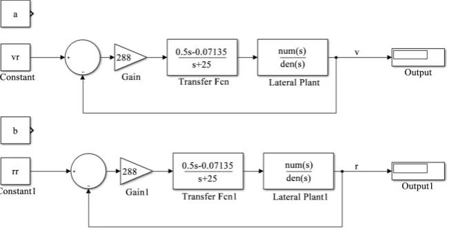
[image:8.595.205.538.498.707.2]where z0 and p0 are the zero and pole of the compensator respectively and Kc is the controller gain. Moreover, for lead compensator zeros should be less than the number of poles i.e.z < p. In addition to phase lead compensator for the lat-eral controller, a yaw angle washout filter in the feedback loop is applied to the lateral sub-model for increasing the system yaw damping mode. This loop is acting in phase lead compensation mode. The block diagram of the control loops of phase lead compensator introduced with lateral velocity and yaw rate are shown in Figure 3. Where Kc is a gain for compensation and for lateral case when rudder is being used as an input “Kc = 288”. The difference between de-sired yaw angle and current aircraft yaw angle is the error signal acting as the reference input for the yaw angle control loop. The gains of the phase lead com-pensator, as well as the positions of its zero and pole are varied to track the step input at the ailerons.
DOI: 10.4236/eng.2018.1010051 712 Engineering Figure 3. Connection of lead compensators with lateral plant for compensating output signal i.e. (a) lateral velocity compensation and (b) yaw rate compensation.
( )
(
(
0)
) ( )
0 ref c
s z
U s K s
s p
ϕ − ϕ
= −
− (15)
Designing a PLC is carried out using root locus technique. The lateral velocity and yawing angle with respect to aileron input for stable response is controlled with PLC, which is sketched in methodology section.
4. Results and Discussion
The optimization of any new unmanned vehicle for stability and control cor-rectness is necessary. As per our design is concerned it was necessary to smoo-then the lateral flight dynamics of the UAV while in flight for which, PID and PID signal constraining was used. In this section results and discussion has been presented for controlling rudder and aileron dynamics. First section is lateral control when rudder is selected as an input and second section is lateral control when aileron is selected as an input.
4.1. Lateral Control When Rudder Is Selected as an Input
This section holds results and discussion of lateral mode control using rudder as an input variable. In this section five major output variables of lateral dy-namics are controlled using rudder. Those five output variables are [v p r phi psi].
4.1.1. Lateral Roll Rate Dynamics Dependent on Rudder Input (PR) Lateral mode gain setting for roll rate dynamics dependent on rudder input are displayed in Table 5.
DOI: 10.4236/eng.2018.1010051 713 Engineering
[image:10.595.211.540.148.253.2]4.1.2. Lateral Roll Angle Dynamics Dependent on Rudder Input (PHIR) Lateral mode gain setting for roll angle dynamics dependent on rudder input are displayed in Table 6.
Table 5. UAV roll rate dynamics dependent on Rudder input (pr).
PID gains Proposed Model Gain specifications
Before signal constraints after signal constraints
Kp 0.0823 0.1059
Ki 2.1226 1.8021
[image:10.595.63.541.276.696.2]Kd 3.6280 3.6281e-06
Table 6. UAV roll angle dynamics dependent on Rudder input (phir).
PID gains Proposed Model Gain specifications
Before signal constraints after signal constraints
Kp 0.0235 0.0337
Ki 0.0105 0.0130
Kd 0.0026 0.0035
DOI: 10.4236/eng.2018.1010051 714 Engineering
Figure 5 represents the stabilization of the rudder input on the roll angle. This can be observed in the closed loop response Figure 5(c) and its root locus are within the proximity of negative s-plane. Moreover, the rudder has little or less effect on the rolling moment of the plane. Therefore it gets stabilized quickly from a disturbed mode. However, initially the response of the closed loop gain is taking time to settle down from disturbed oscillations to steady state. In terms of rolling motion induced due to roll angle, Dutch roll performance is present in the negative s-plane, however, near to the complex axis, demonstrating boun-dary level stability.
[image:11.595.72.538.415.693.2]4.1.3. Lateral YAW Angle Dynamics Dependent on Rudder Input (PSIR) Lateral mode gain setting for yaw angle dynamics dependent on rudder input are displayed in Table 7.
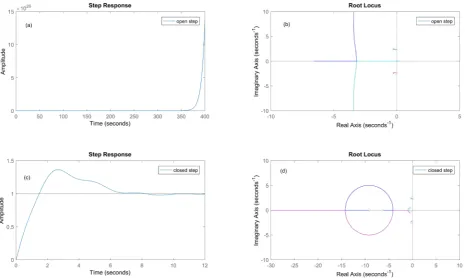
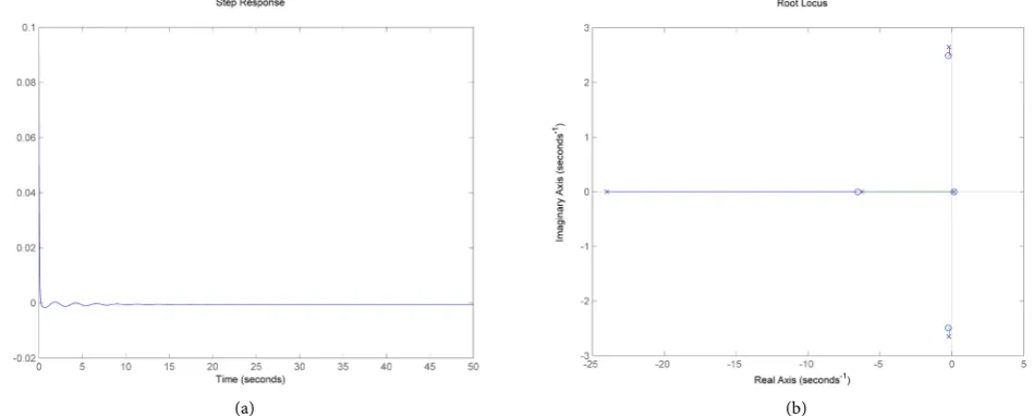
Figure 6 is representing unstable response after setting the closed loop gains for yaw angle with respect to rudder input. This is because the rudder has high influence on the yaw angle of the UAV. Therefore, it requires a compensator to overcome this divergence from the unstable zone. In addition to this, compen-sator was added as shown in Equation (16) to the feedback response of the con-troller to stabilize the yawing angle with respect to rudder input. This compen-sator helps in damping out the unwanted vibrations and oscillations involved in destabilizing of the control surface as shown in Figure 7(a) by the step response of the yaw angle dependent on rudder input. Moreover, the root locus is also in the negative half of the s-plane as shown in Figure 7(b).
DOI: 10.4236/eng.2018.1010051 715 Engineering Figure 6. Root locus and step response of lateral yaw angle dynamics dependent on Rudder input (a) open loop step response, (b) root locus of open loop system, (c) closed loop step response and (d) root locus of closed loop system.
[image:12.595.65.540.399.590.2](a) (b)
Figure 7. When a compensator is added to the psi angle with respect to rudder input; (a) step response (b) root locus.
Table 7. UAV YAW angle dynamics dependent on Rudder input (psir).
PID gains Proposed Model Gain Specifications
Before signal constraints After signal constraints
Kp 0.04008 0.02405
Ki 0.00299 −0.001998
[image:12.595.210.540.645.726.2]DOI: 10.4236/eng.2018.1010051 716 Engineering
Added compensator:
(
)
(
)
0.1 0.1427
25 r
s H
s
− =
+ (16)
with a K = 0.01.
4.1.4. Lateral Yaw Rate Dynamics Dependent on Rudder Input (RR) Lateral mode gain setting for yaw rate dynamics dependent on rudder input are displayed in Table 8.
Figure 8 demonstrates stability in the yawing rate of the UAV after initializ-ing the robust control gains. The stability is demonstrated for the spiral and roll modes, however, spiral mode is marginally stable as it is on the complex axis as shown in Figure 8(d).
4.1.5. Lateral Velocity Dynamics Dependent on Rudder Input (VR) Lateral mode gain setting for lateral velocity dynamics dependent on rudder in-put are displayed in Table 9.
Figure 9 presents high rate of instability for sideslip velocity component when rudder input is used. However, balancing this requires a compensator to be placed, which damps out the response of sideslip entropy. Therefore, compen-sator was added in a lead/lag fashion with a gain as shown in Equation (17). By adding the compensator demonstrated marginable stability over the previous closed loop results without any compensator. This compensator helps in damp-ing out the unwanted vibrations and oscillation involved in destabilizdamp-ing of lat-eral velocity as shown in Figure 10(a) by the step response of the sideslip veloc-ity dependent on rudder input. Moreover, the root locus plot in Figure 10(b)
[image:13.595.209.540.507.598.2]demonstrates the close loop poles are now in negative s-plane region than what was seen before without a compensator in Figure 9(d).
Table 8. UAV yaw rate dynamics dependent on Rudder input (rr).
PID gains Proposed Model Gain Specifications
Before signal constraints After signal constraints
Kp −120.2025 −124.1855
Ki −32787.32 −37799.54
[image:13.595.210.539.633.727.2]Kd 0.01142 0.01612
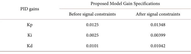
Table 9. UAV velocity dynamics dependent on Rudder input (vr).
PID gains Proposed Model Gain Specifications
Before signal constraints After signal constraints
Kp 0.0125 0.01348
Ki 0.0025 0.00399
DOI: 10.4236/eng.2018.1010051 717 Engineering Figure 8. Root locus and step response of lateral yaw rate dynamics dependent on Rudder input (a) open loop step response, (b) root locus of open loop system, (c) closed loop step response and (d) root locus of closed loop system.
[image:14.595.63.536.405.691.2]DOI: 10.4236/eng.2018.1010051 718 Engineering
(a)
[image:15.595.236.511.69.534.2](b)
Figure 10. Root locus and step response of lateral velocity dynamics dependent on Rud-der input (a) step response and (b) root locus.
Added Compensator:
(
)
0.1 0.1427
25
r
s H
s
− =
+ (17)
with a K = 0.01.
4.2. Lateral Control When Aileron Is Selected as an Input
DOI: 10.4236/eng.2018.1010051 719 Engineering psi].
4.2.1. Lateral Roll Rate Dynamics Dependent on Aileron Input (PA) Lateral mode gain setting for roll rate dynamics dependent on aileron input are displayed in Table 10.
The plot (c) in the Figure 11 shows poles in the negative region of the root locus plot. The modes that can be observed are related with Dutch roll motion of aircraft as the poles are standing on −7.72 ± 8.66 i. The value shows that Dutch roll performance of this aircraft while having input from aileron will give stable performance. Moreover, the rolling mode can create misleading movement in the aircraft motion which can cause undesired banking of the aircraft towards either of the x-axis ultimately making the aircraft to go in spiral mode, therefore, to tackle its stabilization with respect to roll-axis i.e. (x-axis) signal constrained PID were implemented to improve the stability response. In the meanwhile, the closed loop step response shows that the minimum settling time for roll rate on aileron input is less than one second.
[image:16.595.62.537.366.695.2]4.2.2. Lateral Roll Angle Dynamics Dependent on Aileron Input (PHIA) Lateral mode gain settings for roll angle dynamics dependent on aileron input are displayed in Table 11.
DOI: 10.4236/eng.2018.1010051 720 Engineering Table 10. UAV roll rate dynamics dependent on Rudder input (pa).
PID gains Proposed Model Gain Specifications
Before signal constraints After signal constraints
Kp −0.01801 −0.01952
Ki −0.27052 −0.30192
[image:17.595.208.540.211.299.2]Kd 5.4122e-05 7.673822e-05
Table 11. UAV roll angle dynamics dependent on aileron input (phia).
PID gains Proposed Model Gain Specifications
Before signal constraints After signal constraints
Kp 99.840 101.8407
Ki −15.231 −17.8705
Kd −21.781 −22.7704
From the close loop root locus plot of the Figure 12 part (d), some depictions on roll mode and Dutch roll stability can be witnessed. The roll angle stability performance using aileron input is found to control Dutch roll mode around −0.191 ± 2.43 which is in comparatively low stability to that of the roll rate in-put. Moreover, the roll mode performance is in highly stable region of root locus plot when aileron inputs are considered. Aircraft stability about longitudinal axis is also dependent on the roll angle which is an integral response of the roll rate, nevertheless, in Figure 12(c), settling time of closed loop response is stable, de-monstrating the banking of aircraft at any particular angle using aileron will give stable response.
4.2.3. Lateral YAW Angle Dynamics Dependent on Aileron Input (PSIA) Lateral mode gain setting for yaw angle dynamics dependent on aileron input are displayed in Table 12.
The closed loop response of rudder deflection variation due to aileron input in
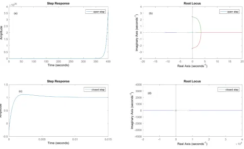
Figure 13(d) demonstrates Dutch roll mode in stable region as depicted earlier before with roll angle and roll rate. This shows that the UAV performance from the control perspective will be highly controllable. Moreover, the roll mode pole in Figure 13(d) is also in controllable region of root locus plot with a stable closed loop step response observed from Figure 13(c). Initially the response overshoots oscillations up to 20 seconds shows adverse yaw effect over the air-craft motion. But the close loop model parameters are deviating the adverse os-cillations to a monotonic decay.
tar-DOI: 10.4236/eng.2018.1010051 721 Engineering geting drone. They used a Dutch roll filter to overcome this instability in drone dynamics. Lateral mode gain setting for yaw rate dynamics dependent on aileron input are displayed in Table 13.
Table 12. UAV YAW angle dynamics dependent on aileron input (psia).
PID gains Proposed Model Gain Specifications
Before signal constraints After signal constraints
Kp −0.0209 −0.0282
Ki −1.2102 −0.0126
[image:18.595.61.536.254.691.2]Kd 0.00374 0.0137
Table 13. UAV YAW rate dynamics dependent on aileron input (ra).
PID gains Proposed Model Gain Specifications
Before signal constraints After signal constraints
Kp −0.01454 −0.02526
Ki 0.00356 0.00362
Kd −0.01669 −0.0167
DOI: 10.4236/eng.2018.1010051 722 Engineering Figure 13. Root locus and step response of lateral yaw angle dynamics dependent on aileron input (a) open loop step response, (b) root locus of open loop system, (c) closed loop step response and (d) root locus of closed loop system.
DOI: 10.4236/eng.2018.1010051 723 Engineering poles, where number of zeros is greater than the poles for PLC. Moreover, fre-quency, gain and phase margin are tweaked to achieve desired response. As compared to PID for the controlling step response of yaw rate with respect to ai-leron input compensator technique is more preferable as shown in Figure 15(a).
Added compensator:
(
)
0.5 0.1427 25 a s H s − =+ (18)
with a gain Ka of 288.
4.2.5. Lateral Velocity Dynamics Dependent on Aileron Input (VA) Lateral mode gain setting for lateral velocity dynamics dependent on aileron in-put are displayed in Table 14.
Figure 16 shows effect of aileron input on the sideslip velocity, it is depicted from above figures that using aileron, sideslip velocity cannot be controlled as it is dependent more on rudder rather than aileron. Moreover, the aileron effects are induced on the x-axis rather than z-axis. This enables smooth control of the rolling not for yawing motion. However, a compensator was added as shown by Equation (19) for controlling the sideslip velocity of the UAV and marginable control was achieved as shown by the Figure 17(b) root locus of the sideslip ve-locity with respect to aileron input. Moreover, the step response is also stable af-ter adding a lead compensator to the laaf-teral plant model. When we are using the PID controller, the response of the lateral velocity with respect to aileron input shows instability. Therefore, to stabilize the response of lateral velocity washout filter in a phase lead compensator arrangement has been inherited to overcome the instability. Moreover, in this case for better transient response phase lead compensator is more preferable due to its minimum rise time to desired lateral response as shown in Figure 17(a).
The compensator that was added to tackle the oscillation is shown in Equation (19); it is a lead compensator as the number of zeros are less than the number of poles.
Added compensator:
(
)
0.5 0.1427 25 a s H s − =+ (19)
[image:20.595.211.538.630.727.2]and also a gain with it K = 288.
Table 14. UAV velocity dynamics dependent on Rudder input (va).
PID gains Proposed Model Gain Specifications
Before signal constraints After signal constraints
Kp −0.0086 −0.0072
Ki −0.00083 −4.2183e-04
DOI: 10.4236/eng.2018.1010051 724 Engineering Figure 14. Root locus and step response of lateral yaw rate dynamics dependent on aileron input (a) open loop step response, (b) root locus of open loop system, (c) closed loop step response and (d) root locus of closed loop system.
DOI: 10.4236/eng.2018.1010051 725 Engineering
[image:22.595.123.478.81.373.2](b)
Figure 15. Washout filter applied to yaw angle with respect to aileron input; (a) step response and (b) root locus.
[image:22.595.62.536.407.695.2]DOI: 10.4236/eng.2018.1010051 726 Engineering
(a)
[image:23.595.218.526.74.595.2](b)
Figure 17. Washout filter applied to sideslip velocity with respect to aileron input; (a) step response and (b) root locus.
5. Conclusion
DOI: 10.4236/eng.2018.1010051 727 Engineering values were hard to analyze for which PID signal constraining was carried out, which enabled to get more precise estimations with considerable optimization in overshoots and settling times. Nevertheless, there were 4 transfer functions that were not easily controllable using either PID or PID signal constraining so PLCs were introduced. PLCs helped in optimizing step outs as well as stretched the poles in the negative half domain of S-plane. This enabled smooth and stable response from the unstable plants that involved; 1) lateral velocity dynamics on rudder input, 2) yaw angle dependent of rudder input, 3) lateral velocity depen-dent of aileron input, and 4) lateral yaw rate dependepen-dent on aileron input. More-over, this research is currently limited to lateral control however, longitudinal control of UAV will be considered for future work with LQR/LQG and Sliding Mode (SM) controllers will be adopted for further smoothness of settling time and overshoots.
Acknowledgements
It is to acknowledge that there is no conflict of authors, as well as, we regards PAF Karachi Institute of Economics and Technology in support for this work.
Conflicts of Interest
The authors declare no conflicts of interest regarding the publication of this pa-per.
References
[1] Shao, P., Zhou, Z., Ma, S. and Bin, L. (2017) Structural Robust Gain-Scheduled PID Control and Application on a Morphing Wing UAV. Proceedings of 36th Chinese Control Conference (CCC), Dalian, China, 26-28 July 2017, 3236-3241.
https://doi.org/10.23919/ChiCC.2017.8027856
[2] Yang, S., Li, K. and Shi, J. (2009) Design and Simulation of the Longitudinal Auto-pilot of UAV Based on Self-Adaptive Fuzzy PID Control. Proceedings of 2009 In-ternational Conference on Computational Intelligence and Security, Beijing, China, 11-14 December 2009, 634-638. https://doi.org/10.1109/CIS.2009.253
[3] Sujit, P., Saripalli, S. and Sousa, J.B. (2014) Unmanned Aerial Vehicle Path Follow-ing: A Survey and Analysis of Algorithms for Fixed-Wing Unmanned Aerial Vehic-less. IEEE Control Systems, 34, 42-59. https://doi.org/10.1109/MCS.2013.2287568
[4] Wahi, P., Raina, R. and Chowdhury, F.N. (2001) A Survey of Recent Work in Adap-tive Flight Control. Proceedings of the 33rd Southeastern Symposium on System Theory, Athens, OH, USA, 20 March 2001, 7-11.
https://doi.org/10.1109/SSST.2001.918481
[5] Tennakoon, W. and Munasinghe, S. (2008) Design and Simulation of a UAV Con-troller System with High Maneuverability. Proceedings of 4th International Confe-rence on Information and Automation for Sustainability, Colombo, Sri Lanka, 12-14 December 2008, 12-14. https://doi.org/10.1109/ICIAFS.2008.4783930
[6] Park, S., Deyst, J. and How, J.P. (2007) Performance and Lyapunov Stability of a Nonlinear Path Following Guidance Method. Journal of Guidance, Control, and Dynamics,30, 1718-1728. https://doi.org/10.2514/1.28957
DOI: 10.4236/eng.2018.1010051 728 Engineering
Controller for Unmanned Aerial Vehicle Using Analytical Redundancy and Ex-tended State Observer. Proceedings of 3rd International Symposium on Systems and Control in Aeronautics and Astronautics, Harbin, China, 8-10 June 2010, 756-761.
[8] Zhu, J.-H. (2006) A Survey of Advanced Flight Control Theory and Application. Proceedings of the Multiconference on “Computational Engineering in Systems Applications”, Beijing, China 4-6 October 2006, 655-658.
[9] Qiu, L., Fan, G., Yi, J. and Yu, W. (2009) Design of Neural Network and Backstep-ping Based Adaptive Flight Controller for Multi-Effector UAV. Proceedings of 2009 IEEE International Conference on Robotics and Biomimetics (ROBIO), Guilin, China, 19-23 December 2009, 1935-1940.
https://doi.org/10.1109/ROBIO.2009.5420545
[10] Qiu, L., Fan, G., Yi, J. and Yu, W. (2009) Robust Hybrid Controller Design Based on Feedback Linearization and µ Synthesis for UAV. Proceedings of 2009 Second In-ternational Conference on Intelligent Computation Technology and Automation, Changsha, 10-11 October 2009, 858-861.
[11] Kada, B. and Ghazzawi, Y. (2011) Robust PID Controller Design for an UAV Flight Control System. Proceedings of the World Congress on Engineering and Computer Science, San Francisco, USA, 19-21 October 2011, 19-21.
[12] Zhu, Z., Liu, K., He, Y., Qi, J. and Han, J. (2013) Model Free Analysis and Tuning of PID Controller. Proceedings of 9th Asian Control Conference (ASCC), Istanbul, Turkey, 23-26 June 2013, 1-7.
[13] Alagoz, B.B., Ates, A. and Yeroglu, C. (2013) Auto-Tuning of PID Controller Ac-cording to Fractional-Order Reference Model Approximation for DC Rotor Con-trol. Mechatronics, 23, 789-797. https://doi.org/10.1016/j.mechatronics.2013.05.001
[14] Liu, G. and Daley, S. (2001) Optimal-Tuning PID Control for Industrial Systems. Control Engineering Practice,9, 1185-1194.
https://doi.org/10.1016/S0967-0661(01)00064-8
[15] Sheibani, A. and Pourmina, M.A. (2012) Simulation and Analysis of the Stability of a PID Controller for Operation of Unmanned Aerial Vehicles. In: Zhang, T., Ed., Mechanical Engineering and Technology. Advances in Intelligent and Soft Compu-ting, Springer, Berlin, Heidelberg.
[16] Eressa, M.R., Zheng, D. and Han, M. (2016) PID and Neural Net Controller Per-formance Comparsion in UAV Pitch Attitude Control. Proceedings of 2016 IEEE International Conference on Systems, Man, and Cybernetics (SMC), Budapest, 9-12 October 2016, 762-767.
[17] Ahsan, M., Shafique, K., Mansoor, A.B. and Mushtaq, M. (2013) Performance Comparison of Two Altitude-Control Algorithms for a Fixed-Wing UAV. Pro-ceedings of 3rd IEEE International Conference on Computer, Control and Com-munication (IC4), Karachi, Pakistan, 25-26 September 2013, 1-5.
[18] Adil Loya, K.M. and Duraid, M. (2018) Quantification of Aerodynamic Variables Using Analytical Technique and Computational Fluid Dynamics. Proceedings of 20th International Conference on Computational Fluid Dynamics, Barcelona, Spain, 29-30 October 2018.
DOI: 10.4236/eng.2018.1010051 729 Engineering
Control for Aircraft Pitch Autopilot. Journal of Space Technology,1, 51-56. [21] Rhee, I., Cho, S., Park, S. and Choi, K. (2012) Autopilot Design for a Target Drone
![Table 1. UAV design specifications [7].](https://thumb-us.123doks.com/thumbv2/123dok_us/9259122.415271/5.595.181.538.72.252/table-uav-design-specifications.webp)