ISSN: 1816-949X
© Medwell Journals, 2019
Design and Development of Secure Efficient Wireless Communication
System based on FHSS
1
Samir Jasim and
2Ahmed M. Alfadhel
1
Department of Electrical Engineering, University of Babylon, Hillah, Iraq
2
Department of Communication Techniques, Al-Furat Al-Awsat Technical University, Kufa, Iraq
Abstract: As far as there is a need to increase the efficiency of data transfer, the trials of developments communication systems are appeared. In this study, four modulation techniques and three PN sequence code lengths are studied, to indicate the best performance. The study included BER calculations for each modulation technique or PN code is used in this FHSS system. MATLAB Simulink with run time of 10 is used to simulate each modulation technique. And Additive White Gaussian Noise (AWGN) channel is used as an RF channel. Finally, after we present the simulation results, we deduce which modulation technique is the most suitable for FHSS system and what is the advantage of the longer PN code.
Key words: FHSS, modulation technique, PN sequence code length, BER, AWGN channel, communication
INTRODUCTION
One of spread spectrum techniques is Frequency Hopping Spread Spectrum (FHSS). This technique its origins back to the mid-1950s when blades system was made (Scholtz, 1982). Although, FHSS system needs a large number of frequencies but it offers secure transmission, interference rejection, low power transmission, selective addressing and the possibility of multiple access (Dixon, 1994).
A frequency hopping generator is the heart of a FHSS system. In more details, it consists of two main components, the first is PN code generator. It generates a code with a specific lengths such as 8, 16, 32 and 64, so on. In fact, many of military communications systems depends on FHSS, since, the possibility that two FHSS that have different PN codes but occupy the same band is to hop the same frequency at the same time is “more or less randomly” (Dixon, 1994).
The second component is a frequency synthesizer. It works to hop between one frequency and another by depending on the incoming PN sequence code.
Many factors control the efficiency of data transmission in FHSS system such as hopping rate, PN sequence code length, data rate, modulation technique. Two factors are handled here, they are PN code length and modulation technique. Frequency modulation techniques are always used with FHSS, since, the percentage of correct identification is “approximately constant around 99%” without taking into account C/N value, since, it has no effect when using frequency modulation techniques (Subhi and Jabir, 2008).
Literature review: Establishing a communication link using FHSS technique grants several merits. Hence, this technique is existed in wireless mobile system then in wireless computer networks (Turcotte and Wickert, 1989; Falsafi and Pahlavan, 1995). But it is important to know that FHSS technique is slower than DSSS technique in synchronization process, for this synchronization techniques are proposed to enhance the system (Mason and Felstead, 1991).
By appearance of emerging technologies, engineers found themselves need to make systems that handle enormous amount of data, consume minimum power as possible and with flexible design. Consequently, FHSS technique found its way to be implemented by new methods, pushing the performance of this technique to higher levels. For instance, Wu et al. (2002) implemented a FHSS using a coarse-grained FPGA architecture. While Park et al. (2010) proposed a new algorithm for Adaptive Frequency Hopping (AFH).
FHSS technique found its implementation in many applications. Each of Wu et al. (2002), Park et al. (2010), Jasim et al. (2016) presented a system design to be used with medical technical equipments. Recently, FHSS is used in spectrum sensing for Cognitive Radio (CR) purpose (Saber et al., 2018) and for frequency hopping pattern recognition purpose (Gu and Goodman, 2018).
MATERIALS AND METHODS
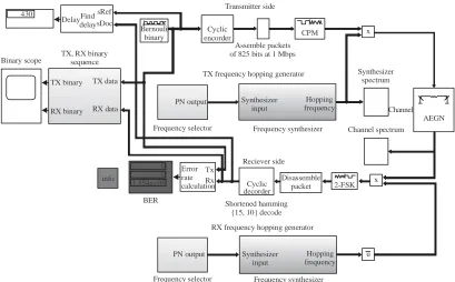
System design: Park et al. (2010) proposed a system design consists of transmitter, frequency hopping generator, transmission channel and receiver. Figure 1 shows a general block diagram of the system.
Fig. 1: System design
Transmitter side: Firstly, it consists of Bernoulli Binary Generator block. This block generate a different random data stream at each run. With a specific probability of zeros and ones. Moreover, controlling the sample time in this block will give the required data rate. Bernoulli block is followed by binary cyclic encoder block to correct random errors that occurred during the transmission channel. Where 10/15 encoder rate is used, since, the input message length (K) is 10 and the output codeword length (N) is 15. Then a buffer will assemble data bits in packets of size 625 bits at rate of 1 Mbps. In more details, a data rate of 1 Mbps is achieved as follow:
-6
1/(1.5×10 )×15/10 = 1 Mbps
where, 1.5×10G6 second is the sample time that is used in
Bernoulli block while 15/10 is output to input encoder rate.
After that a modulator block is used to modulate the data bits. In fact, four modulation techniques will be implemented in this design which they are CPM (Continuous Phase Modulation), CPFSK (Continuous Phase Frequency Shift Keying), MSK (Minimum Shift Keying) and GMSK (Gaussian Minimum Shift Keying). Channel: An Additive White Gaussian Noise (AWGN) channel is used with the system design. The channel is inserted after the modulated signal is spread by a high frequency coming from the hopping generator.
Signal to Noise ratio (Eb/No) mode is used with input
signal power, referenced to 1 Ω is 0.208 W and symbol period is 10G6 sec.
Frequency hopping generator: The main purpose of this part of the design is to select a hopping frequency from a set of frequencies. In practical situation the hopping generator is existed in transmitter side and receiver side. Furthermore, a synchronization is required between both generators in order todespread (correlate) the received signal correctly.
A Linear Feedback Shift Register (LFSR) with maximal length of 63 is used with 1/9600 sec sample time and 6 samples per frame. These parameters give a hopping frequency of 1600 hop/sec.
Then a 64 FSK modulator is used as a frequency synthesizer. At each time 6 samples arrived from the LFSR, then a frequency hop is selected. One more thing, a separation frequency of 1 MHz is used between one hop and another.
Receiver side: Firstly, a multiplier is used to multiply each of the AWGN channel output signal and the conjugate of the hopping frequency signal in order to correlate (despread) the spread signal. Then a demodulator block is used, this block is required to demodulate the despread signal to a baseband signal. After that data packets are disassembled by buffer block. Finally, to get the original transmitted data signal we have to decode the disassembled signal by using binary cyclic decoder block. One more block is used at the receiver, for error rate calculations which it is BER block. The total design is carried out by MATLAB Simulink. Figure 2 shows the complete design of the system.
Transmitter
Data
source Encoder Buffer Modulator
PN code synthesizer Frequency
Conjugate
BER calculator
Frequency hopping generator
Receiver
Decoder Buffer Demodulator
430
Transmitter side
DelayFind delay
sRef
sDoc
Bernouli binary
Cyclic encorder
Assemble packets of 825 bits at 1 Mbps
CPM x
Binary scope TX, RX binarysequence
TX binary
RX binary TX data
RX data
PN output
PN output Frequency selector
Frequency selector info
0 0 1.154e+05
BER
Error rate calculation
Tx Rx
Synthesizer input
Synthesizer input
Hopping frequency
Hopping frequency
Synthesizer spectrum
Channel TX frequency hopping generator
RX frequency hopping generator Frequency synthesizer
Frequency synthesizer Reciever side
u Channel spectrum
2-FSK Cyclic
decorder
Disassemble
packet x
Shortened hamming {15, 10} decode
[image:3.612.101.510.93.347.2]AEGN
[image:3.612.102.519.534.637.2]Fig. 2: Complete system design
Fig. 3: Frequency synthesizer output
Fig. 4: AWGN channel output
RESULTS AND DISCUSSION
It is more appropriate to view the hop spectrum and channel spectrum before listing the main results sections for this Fig. 3 and 4 show that, respectively.
In Fig. 3 the spectral component is pointing to 2 MHz, however, a 2 MHz here stands for 34 MHz, the actual component, since, the analyzer split the 64 hopping frequencies into two halves by set 32 frequencies in the positive side and the same
-55
-60
-65
-70
-75
-80
Magn
itu
de (d
BW
/H
z)
Frequency (MHz) Hopping spectrum
-50 -40 -30 -20 -10 0 10 20 30 40 50
-55
-60
-65
-70
-75
-80
Magn
itu
de (d
BW
/H
z)
Frequency (MHz) Channel spectrum
100
10-1
10-2
10-3
10-4
10-5
10-6
B
it
e
rr
o
r
ra
te
0 2 4 6 8 10 12
E /N (dB)b 0
100
10-1
10-2
10-3
10-4
10-5
10-6
B
it
e
rr
o
r
ra
te
0 2 4 6 8 10 12 E /N (dB)b 0
100
10-1
10-2
10-3
10-4
10-5
10-6
B
it
e
rr
o
r
ra
te
0 2 4 6 8 10 12 E /N (dB)b 0
100
10-1
10-2
10-3
10-4
10-5
10-6
B
it
e
rr
o
r
ra
te
[image:4.612.331.531.98.208.2]0 2 4 6 8 10 12 E /N (dB)b 0
Fig. 5: BER versus Eb/No in FHSS system with CPM
modulated signal
Fig. 6: BER versus Eb/No in FHSS system with CPFSK modulated signal
in the negative side. While in Fig. 4 the spectral component is pointing to -26 MHz which stands for 6 MHz.
The rest of results are divided into five sections. In the first four sections, the transmission and reception is carried out using the four modulation techniques, one by one. In the meanwhile, BER is calculated over a set of Eb/No values. While final section is dedicated to test three
PN sequence code lengths with the modulation technique that gave best BER calculations.
Section 1; CPM: CPM technique is used as a modulator with Gaussian pulse shape while 2-FSK demodulator block is used at receiver side, since, 2-FSK demodulator gave a better performance than CPM demodulator. Figure 5 shows BER versus set values of Eb/No in FHSS system with CPM modulated signal.
Section 2; CPFSK: CPFSK technique is used as a modulator, also 2-FSK demodulator is used in receiver side, since, 2-FSK demodulator gave a better performance.
[image:4.612.323.528.243.361.2]Here, BER calculations showed a significant rise in comparison with CPM modulation technique. Figure 6 shows BER versus set values of Eb/No in FHSS system with CPFSK modulated signal.
Fig. 7: BER versus Eb/No in FHSS system with MSK
[image:4.612.86.288.259.370.2]modulated signal
Fig. 8: BER versus Eb/No in FHSS system with GMSK
modulated signal
Section 3; MSK: In this case MSK modulator block is used in the transmitter side and also 2-FSK demodulator block is used in the receiver side for same previous reason.
Back to our point of study, BER calculations in this case showed a similar behavior with previous case. In fact, there is no difference between MSK and CPFSK in BER calculations as shown in Fig. 7.
Section 4; GMSK: In this case GMSK modulator block is used in the transmitter side while GMSK demodulator block is used in the receiver side.
However, BER calculations showed a steady behavior over the selected set of Eb/No values. In fact, BER values were equal to 0.05 . As shown in Fig. 8. To sum up, Fig. 9 shows BER behavior of the four modulation techniques together.
It is clear that CPM modulation technique gave the best BER in this FHSS system design, in comparison to the other three types.
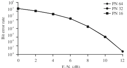
Section 5; 16, 32, 64 PN code lengths: In this time, the PN code length is altered, while CPM technique is remained unchanged in each case. As in previous sections, a set of Eb/No values are taken to measure BER
each time.
100
10-1
10-2
10-3
10-4
10-5
10-6
B
it
e
rr
o
r
ra
te
0 2 4 6 8 10 12 E /N (dB)b 0
CPM CPFSK
MSK GMSK
100 10-1
10-2 10-3
10-4
10-5 10-6 -7 10
-8 10
B
it
e
rro
r r
ate
0 2 4 6 8 10 12
E /N (dB)b 0
[image:5.612.82.282.94.202.2]PN 64 PN 32 PN 16
Fig. 9: BER versus Eb/No in FHSS system of four modulated signals
Fig. 10: BER versus Eb/No in FHSS system for three PN code lengths
CONCLUSION
In this FHSS system, we have tested four modulation techniques and three PN sequence code lengths. The implementation results showed that lowest BER can be achieved using CPM technique.
On the other side, the test results of PN code lengths, showed that they don’t affect BER value. This leads to a conclusion about PN length, that the longer PN sequence code will have the lower probability to hop the same frequency at the same time with another PN code located in the same band.
Finally, for further work in future, it is possible to investigate the possibility of increasing data rate of FHSS system. And this research is adhesive with increasing hopping rate of FHSS system.
ACKNOWLEDGEMENTS
The researchers would like to thank Hamzah Sabr, PhD candidate student for his valuable discussions and his continuous support for this research.
REFERENCES
Dixon, R.C., 1994. Spread Spectrum Systems: With Commercial Applications. 3rd Edn., Wiley, Hoboken, New Jersey, USA., ISBN: 978-0-471-59342-3, Pages: 592.
Falsafi, A. and K. Pahlavan, 1995. A comparison between the performance of FHSS and DSSS for wireless LANs using a 3D ray tracing program. Proceedings of the 1995 IEEE 45th Vehicular Technology Conference on Countdown to the Wireless Twenty-First Century Vol. 2, July 25-28, 1995, IEEE, Chicago, IL, USA., pp: 569-573. Gu, Y. and N.A. Goodman, 2018. Information-theoretic
compressive measurement for frequency hopping pattern recognition. Proceedings of the 2018 IEEE International Radar Conference (Radar Conf 18), April 23-27, 2018, IEEE, Oklahoma City, OK, USA., pp: 1445-1449.
Jasim, S., A.T. Jaiad and H. Sabr, 2016. Security enhancement of wireless systems by using frequency Hopping Technique. Int. J. Comput. Sci. Mob. Appl., 4: 7-14.
Mason, L.J. and E.B. Felstead, 1991. An estimation method for fine-time synchronization of FH systems using the early-late filter technique. Proceedings of the MILCOM 91-Conference Record, November 4-7, 1991, IEEE, McLean, VA, USA., pp: 1059-1063.
Park, K.J., T.R. Park, C.D. Schmitz and L. Sha, 2010. Design of robust adaptive frequency hopping for wireless medical telemetry systems. IET. Commun., 4: 178-191.
Saber, M., H.K. Aroussi, A. El Rharras and R. Saadane, 2018. Raspberry pi and RTL-SDR for spectrum sensing based on FM real signals. Proceedings of the 2018 6th International Conference on Multimedia Computing and Systems (ICMCS 18), May 10-12, 2018, IEEE, Rabat, Morocco, pp: 1-6.
Scholtz, R.A., 1982. The origins of spread-spectrum communications. IEEE Trans. Commun., 30: 822-854.
Subhi, W. and S. Jabir, 2008. Modulation and frequency estimation of FHSS signal in the presence of interference environments. Proceedings of the 1st International Regional Conference of Engineering Science, November 5-6, 2008, Nahrain University, Baghdad, Iraq, pp: 1-19.
Turcotte, R.L. and M.A. Wickert, 1989. Exact probability of error analysis for FHSS/CDMA communications in the presence of single term Rician fading. Proceedings of the IEEE Military Communications Conference on Bridging the Gap, Interoperability, Survivability, Security, October 15-18, 1989, IEEE, Boston, MA., USA., pp: 134-138.
[image:5.612.83.286.253.362.2]