Abstract— Biometric identification has featured prominently for individuals with fingerprint emerging as the dominant one. The dominance of fingerprint is been established by the continuous emergence of different forms of Automated Fingerprint Identification Systems (AFIS). In the course of performing its assigned roles, an AFIS conducts a lot of activities including fingerprint enrolment, creation of its profile database and minutiae enhancement which involves image segmentation, normalization, Gabor filter, binarization and thining. The activities also involve extraction of minutiae, pattern recognition and matching, error detection and correction and decision making. In this paper, a minutiae-based algorithm for fingerprint pattern recognition and matching is proposed. The algorithm uses the distance between the minutiae and core points to determine the pattern matching scores for fingerprint images. Experiments were conducted using FVC2002 fingerprint database comprising four datasets of images of different sources and qualities. False Match Rate (FMR), False Non-Match Rate (FNMR) and the Average Matching Time (AMT) were the statistics generated for testing and measuring the performance of the proposed algorithm. Findings from the experimental study showed the effectiveness of the algorithm in distinguishing fingerprints obtained from different sources with average FMR of 0%. It is also revealed that the ability of the algorithm to match images obtained from same source is heavenly dependent on the qualities of such images.
Index Terms— Minutiae, Pattern Matching, FNMR, FMR,
FVC2002, Fingerprint
I. INTRODUCTION
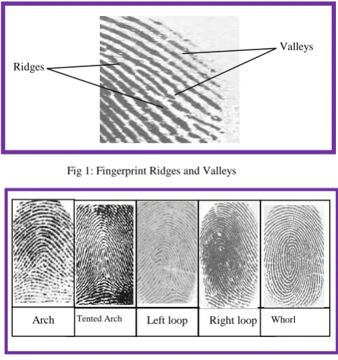
ingerprint is an impression of the friction ridges of all or any part of the finger. It is a deposit of minute ridges and valleys formed when a finger touches a surface. The extracted ridges and valleys from a fingerprint image are shown in Figure 1 with the ridges represented by raised and dark portions while the valleys are the white and lowered regions. A fingerprint is classified as an enrolled or latent print [1]. An enrolled fingerprint may be obtained when a person is arrested for a criminal act. As part of the investigation process, the security agent such as a police
Manuscript received August 15, 2013 revised on October 11, 2013. O. C. Akinyokun is with the Federal University of Technology, Akure, Nigeria, e-mail: akin1 [email protected], +2348034059344
B. K. Alese is with the Federal University of Technology, Akure, Nigeria, e-mail: [email protected], +2348034540465
G. B. Iwasokun is with the Federal University of Technology, Akure, Nigeria, e-mail: [email protected], +2348130622747
officer will roll the arrestee’s fingertip in ink before it is pressed on a card to obtain the impression. The fingerprint card is then stored in a library of such cards. Enrolled fingerprints may also be obtained with modern day fingerprint scanner [2, 3]. Latent print on its own, is typically produced at a crime scene and is usually not readily visible. It occurs when the natural secretions of the skin are deposited on a surface through fingertip contact at the crime scene. The most appropriate method for rendering latent fingerprints visible, so that they can be photographed, is complex and depends, for example, on the type of surface involved. A ‘developer’, usually a powder or chemical reagent, is often used to produce a high degree of visual contrast between the ridge patterns and the surface on which the fingerprint was left [1, 4].
Whether enrolled or latent fingerprint, there is an exclusive owner. This implies that no two individuals including identical twins are expected to possess same fingerprints [5, 6]. Facts also exist that the ridges of individual finger never change throughout his or her lifetime no matter what happens. Even in case of injury or mutilation, they will always reappear within a short period. The five commonly found fingerprint ridge patterns are arch, tented arch, left loop, right loop and whorl. Examples of these patterns are shown in Figure 2 [5 - 10].
In the arch patterns, the ridges enter from one side, make a rise in the center and exit generally on the opposite side.
Fingerprint Matching Using Spatial
Characteristics
Akinyokun Oluwole C., Alese Boniface K., and Iwasokun Gabriel B.
F
Ridges
[image:1.595.304.546.495.753.2]Valleys
Fig 1: Fingerprint Ridges and Valleys
Fig 2: Types of thumbprints patterns
Tented Arch Left loop Right loop Whorl
The ridges in the tented arch enter from either side, re-curve and pass out or tend to pass out the same side they entered in the loop pattern. In the right loop pattern, the ridges enter from the right side while the ridges enter from the left side in the left loop. In a whorl pattern, the ridges are usually circular round the core point.
Fingerprint has proved to be a very reliable human identification and verification index which has enjoyed superiority over all other biometrics including ear, nose, iris, voice, face, gait and signature [11]. The uniqueness of the ridges makes it immutable and therefore serves a strong mark for identity. Issues involved in creating, using, changing and ending an identity cuts across technical, business, legal, medicine, security, crime investigation, procedural and policy dimensions. During fingerprint verification, an input fingerprint is compared with a previously enrolled fingerprint to determine if the two fingerprints come from the same finger or not (1:1 match) [9]. The major reasons for the high superiority and wide use of fingerprints for identification and verification are availability for all individuals in respective of race, gender or age and availability of easy, smooth operational and cheap fingerprint capturing devices. Other reasons include permanent form of pattern or structure over time is retained and the distinct and highly unique form of individuals’ features is permanently maintained.
The components of fingerprints that are mostly responsible for their high performance in identification and verification systems are categorized into three levels [3, 12]. Level One component consist of the macro details, which include friction ridge flow, pattern type, and singular points. These components are mainly used for categorizing fingerprint images into major pattern types. Level Two components are minutiae such as ridge bifurcations and endings. These components show significant variation from one fingerprint to another. Level Three components are the dimensional attributes of the ridge such as ridge path deviation, width, shape, pores, edge contour and other details including incipient ridges, creases, and scars. Level Two and Level Three components are mostly used for establishing fingerprints’ individuality or uniqueness.
Fingerprint pattern matching is carried out when the need for ascertaining the exactness or variations among fingerprint images arises. It involves the generation of matching scores by using the Level One and Level Two components [13]. When fingerprints from the same finger are involved, the matching scores are expectedly high and low for fingerprints from different fingers. Fingerprint matching faces a number of challenges including large intra-class variations (variations in fingerprint images of the same finger) and large interclass similarity (similarity between fingerprint images from different fingers). Intra-class variations are caused by finger pressure and placement (rotation, translation) and contact area with respect to the sensor and condition of the finger such as skin dryness and cuts. On the other hand, interclass similarity can be large because there are only three major types of major fingerprint patterns; namely arch, loop, and whorl [3].
A number of fingerprints pattern matching methods exist. Each of these methods has its strengths and weaknesses [3].
In this study, an algorithm for fingerprint pattern matching based on the direct distance testing and measurement of fingerprint minutiae and its core point is developed. The core point of an image is the point of maximum or minimum ridge turning. At this point, the ridge gradient is zero. Section 2 presents the review of some related works. Section 3 presents minutiae based algorithm for fingerprint pattern matching. The case study of the benchmark fingerprints jointly produced by The Biometric Systems Laboratory, Bologna, Pattern Recognition and Image Processing Laboratory, Michigan and the Biometric Test Center, San Jose, United States of America was carried out in Section4. The findings from the case study and conclusion drawn are presented in Section 5.
II. LITERATURE REVIEW
Various techniques have been formulated by different authors for the matching of fingerprints. One of these is the minutiae based technique that has witnessed a lot of interest from different research groups. Minutiae based fingerprint pattern matching method is widely adopted for the fact that fingerprint minutiae are generally known to be the most unique, durable and reliable features. In addition, the template size of the biometric information base on minutiae is much smaller and the processing completion time is always lower than in other techniques such as graph-based fingerprint matching. These characteristics are very important for saving memory and input-output processing time [14]. In most cases, minutiae based matching algorithm is designed for solving problems of correspondence and similarity computation. Each minutia was assigned texture-based and minutiae-texture-based descriptors for the correspondence problem in [15]. An alignment-based greedy matching algorithm was then used to establish the correspondences between minutiae. For the similarity computation, a 17-D feature vector was extracted from the matching result, and the feature vector is then converted into a matching score using support vector classifier. This method is comparative to the best algorithms even though its performances may change when some information such as ridges, orientation and frequency images are not used.
The Euclidean space and ridge-based relative features among minutiae reinforce each other in the representation of a fingerprint. The authors in [16] proposed a novel algorithm based on global comprehensive similarity with three phases. Firstly, a minutia-simplex that contains a pair of minutiae as well as their associated textures was built to describe the Euclidean space-based relative features among minutiae. Its transformation-variant and invariant relative features were employed for the comprehensive similarity measurement and parameter estimation respectively. Secondly, the ridge-based nearest neighbourhood among minutiae was used to represent the ridge-based relative features among minutiae. With this approach, minutiae were grouped according to their affinity with a ridge. Finally, the relationship between transformation and the comprehensive similarity between two fingerprints was modeled in terms of histogram for initial parameter estimation. Experimental results show the effectiveness and suitability of the method for limited Proceedings of the World Congress on Engineering 2014 Vol I,
memory Automated Fingerprint Identification Systems (AFISs) owing to its very minimal template size.
Latent fingerprint identification is of critical importance to law enforcement agencies in identifying suspects. They are inadvertent impressions left by fingers on surfaces of objects. While tremendous progress has been made in plain and rolled fingerprint matching, latent fingerprint matching continues to be a difficult problem. Poor quality of ridge impressions, small finger area, and large nonlinear distortion are the main difficulties in latent fingerprint matching compared to plain or rolled fingerprint matching. A system for matching latent fingerprints found at crime scenes to rolled fingerprints enrolled in law enforcement databases has been proposed in [17]. Extended features, including singularity, ridge quality map, ridge flow map, ridge wavelength map, and skeleton were used. The matching module consists of minutiae, orientation field and skeleton matching. The importance of various extended features was studied and the experimental results indicate that singularity, ridge quality map and ridge flow map are the most effective features in improving the matching accuracy. However, the proposed latent matching algorithm is still inferior to the performance of experienced latent examiners, which may be caused by the methodologies for matching ridge skeleton, minutiae and detailed ridge features. It may also be caused by difference in the approach to utilizing negative evidence.
With identity fraud in every society assuming increasing trend and with rising emphasis on the emerging automatic personal identification applications, the need for biometrics-based verification system continued to increase. Fingerprint-based identification is therefore receiving a lot of attention. The traditional approaches to fingerprint representation suffers shortcomings including difficulty in the automatic detection and extraction of complete ridge structure as well as difficulty in quick matching of fingerprint images containing different number of unregistered minutiae points. The authors in [18] proposed a filter-based algorithm that uses a bank of Gabor filters to capture both local and global details in a fingerprint as a compact fixed length FingerCode. Fingerprint matching was based on the Euclidean distance between the two corresponding FingerCodes. The experimental results show that the algorithm was extremely fast with high verification accuracy which was only marginally inferior to the best results of minutiae-based algorithms presented in [19]. The proposed system performed better than a state-of-the-art minutiae-based system when the performance requirement of the application system does not demand a very low false acceptance rate.
The basic idea in several minutiae based techniques is connecting the neighbor minutiae with triangles using a Delaunay triangulation and analyzing the relative position and orientation of the grouped minutiae. Even if rotations, translations and non-linear deformations are present, the obtained triangular structure does not change significantly, except where the feature extraction algorithm fails [20, 21]. That technique provides a good processing time, describes the minutia relationship with consistency and works well with the nonlinear distortions. However, for genuine match,
the overlapping area between the matching fingerprints should be large.
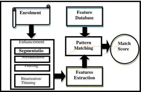
During minutiae-based fingerprint pattern matching, a match score between two fingerprints is computed based on the characteristics exhibited by the minutiae. Minutiae-based pattern matching is mostly used because forensic examiners have successfully relied on minutiae to match fingerprints for a long period of time. Minutiae-based representation is storage efficient and expert testimony about suspect identity based on mated minutiae is admissible in courts of law [3]. The latest trend in minutiae matching is to use local minutiae structures to quickly find a permissible alignment between two fingerprints and then consolidate the local matching results at a global level. This kind of matching algorithm typically consists of the steps conceptualized in Figure 3.
The first step of the algorithm is the fingerprint enrolment. Depending on choice, a manual method using ink and paper or the electronic sensing method may be used [9]. The enrolled fingerprint is then enhanced for smooth and speedy extraction of minutiae. The enhancement of fingerprint involves ridge segmentation, normalization, orientation estimation, frequency estimation, Gabor filtering, binarization and thinning [22-24]. The minutiae points are the points that uniquely describe any fingerprint image. A minutia point is described by type, location and orientation. Algorithms for the extraction of minutiae points from thinned fingerprint images have been proposed in [12, 13, 22, 23]. A number of these algorithms use the 8-nearest neighbours approach to extract a ridge point as a bifurcation, ending, isolated, continuing or crossing point [10]. During feature matching, a pairwise similarity between minutiae sets of two fingerprints is computed. This is done by comparing minutiae descriptors that are invariant to rotation, size and translation. The two fingerprints are aligned according to the most similar minutiae pair and the algorithm then establishes minutiae that are close enough both in location and direction. A match score is finally computed to reflect the degree of match between the two fingerprints based on factors such as the number of matching minutiae, the percentage of matching minutiae in the overlapping area of the two fingerprints and the consistency of ridge count between the minutiae [3]
Features Extraction
Pattern
Matching Match Score Enhancement
Segmentation
Normalization Filtering
Binarization/ Thinning
[image:3.595.305.549.242.401.2]Figure 3: A typical fingerprint pattern matching steps
Fig 3: A typical fingerprint pattern matching steps
Enrolment
Features Extraction
Pattern Matching
Match Score Feature
Database
Segmentatio n
Filtering Normalization
Enhancement
Binarization/ Thinning Proceedings of the World Congress on Engineering 2014 Vol I,
III. THE PROPOSED FINGERPRINT PATTERN MATCHING ALGORITHM
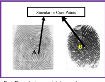
A new method for generating fingerprints matching scores using the spatial parameters existing between the minutiae points is proposed. The motivation behind the algorithm is the need to address the matching problems due to image ridge orientation and size variations. The algorithm take advantage of the fact that the relative distance to the core point from each minutia point does not change irrespective of the image directional flow for a given image size. The core point is the point of maximum turning at which the gradient is zero. The core points A and B shown in Figure 4 are the points of maximum turning of the ridge structures in the two images. They are also the points where the directional fields experience total orientation changes [24, 25].
Among the common feature points that uniquely describe a fingerprint image are bifurcations and ridge endings [13, 23], which are represented by circles and squares respectively in Figure 5. The core points are represented with the thick diamonds.
Figure 6 illustrates typical interconnecting lines between nine (9) minutiae points labeled A, B, C, D, E, F, G, H and I and the core point O in a region of an image.
The connecting lines are in different directions with lengths proportionate to the distances from point O to the connecting minutiae points.
The procedure for the proposed algorithm is in the following phases:
a. Obtain the core point using the following procedure [26].
Divide the fingerprint image, I, into blocks of size N x N.
Compute the orientation estimate for the center pixel A(i,j) of each block.
Compute the sine component in radian of each estimate using sin(A( i , j ))
A perfectly horizontal ridge has a sine component of 0 while vertical ridge has a sin component of 1. Due to the discontinuity property, the sine component value always changes abruptly from 0 to 1 or vice versa at the core point. In view of this, the following additional operations are performed:
Initialize a 2 dimensional array B(i,j) and set all its entries to 0.
Scan the sine components map in a top-to-bottom, left-to right manner.
For each sine component
B(i,j)=Sine(A(i,j)), (1) If B(i, j) <A threshold and B(i - 1, j) > p / 2 and B(i + 1, j) > p / 2 then
Compute the difference D between the sine components for block with center at pixel (i,j) and another block with center pixel at (k,l) using the formula:
D = Sin(i,j) –Sin(k,l) (2) C(i,j) entry is used to compute the continuity of a possible
reference candidate point and is defined as:
End if
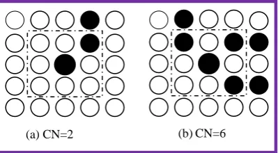
b.Obtain the x and y coordinates for all the true bifurcations and ridge endings in the thinned image. The Crossing Number (CN) value for a candidate ridge ending and bifurcation is obtained according to the formula [12, 13]:
N1, N2, …, N8 denote the 8 neighbours of the candidate
[image:4.595.81.253.263.398.2]minutia point in its 3 x 3 neigbourhood. The 8 neigbours of a candidate pixel N are scanned in clockwise direction as shown in Table I.
Table I: 8 Neighbours of a candidate minutia pixel N.
N2 N3 N4
N1 N N5
N8 N7 N6
[image:4.595.40.286.475.594.2]O A
Fig 4: Fingerprint images and their core points Singular or Core Points
B
A
Fig 5: Feature points for skeleton and original images (a) Skeleton image (b) Original image
O
A B
C
D E
F H I
G
Fig 6: Interconnecting lines between feature and core points
[image:4.595.46.264.644.775.2]As shown in Fig 7, a ridge pixel with CN value of 2 corresponds to a ridge ending and a CN value of 6 corresponds to a bifurcation.
To ensure that only valid minutiae are extracted from the image, a minutiae validation algorithm proposed in [13] is implemented. The algorithm tests the validity of each candidate minutia point by scanning the skeleton image and examines its local neighbourhood. Firstly, an image M of size W x W centered on the candidate minutia point in the skeleton image is created. Secondly, the central pixel of M is labelled with a value of 2 and the rest of the pixels in M are initialised to values of zero. Subsequent steps depend on whether the candidate minutia point is a ridge ending or a bifurcation.
For a candidate bifurcation point:
Examine the 3 x 3 neighbourhood of the bifurcation point in a clockwise direction. For the three pixels that are connected with the bifurcation point, label them with the value of 1.
Also label with 1 the three ridge pixels that are linked to the three connected pixels.
Count in a clockwise direction, the number of transitions from 0 to 1 (T01) along the border of image M.
If T01 = 3, then the candidate minutia point is validated as
a true bifurcation.
For a candidate ridge ending point:
Label with a value of 1 all the pixels in M, which are in the 3 x 3 neighbourhood of the ridge ending point.
Count in a clockwise direction, the number of 0 to 1 transitions (T01) along the border of image M. If T01 = 1,
then the candidate minutia point is validated as a true ridge ending.
c. The distance, i between the ith minutia point Pi(ai,bi)
and the image core point M( ) is obtained from:
d. The degree of closeness is obtained for matching image K with image L by using the formula:
s is the smaller of the respective number of feature points in the two images, G(i) and H(i) represent the distance
between the ith minutia point and the core points in K and L
respectively.
e. The correlation coefficient value, S between K and L, is then computed as the pattern matching score by using the formula:
From this formula, the closeness value will be = 0 for exact or same images and, consequently, the matching score will be S = 1.
IV. EXPERIMENTAL RESULTS
The implementation of the proposed fingerprint matching algorithm was carried out using Matlab version 7.6 on Ms-Window Vista Home Basic Operating System. The experiments were performed on a Pentium 4 – 2.10 GHz processor with 1.00GB of RAM. The experiments were conducted for the analysis of the performance of the proposed algorithm when subjected to images of various qualities. The experiments also serve the basis for the generation of metric values relevant for the comparison of the obtained results with results from related works. The case study of fingerprint images obtained from Fingerprint Verification Competition was carried out. The fingerprints are in four datasets DB1, DB2, DB3 and DB4 of FVC2002 fingerprint database [27] whose summary is presented in Table II.
The database contains benchmark fingerprints jointly produced by The Biometric Systems Laboratory, Bologna, Pattern Recognition and Image Processing Laboratory, Michigan and the Biometric Test Center, San Jose, United States of America. Each of the four datasets contains 80 images of different qualities. The 80 fingerprints are made up of 5 fingerprints from 16 different fingers. The first two datasets were acquired using an optical fingerprint reader. The third and fourth datasets were acquired using capacitive fingerprint reader and computer software assistance respectively. False non-match rate (FNMR), false match rate (FMR) and average matching time(AMT) were the indicators that were measured. These indicators were chosen because they are among the commonest indicators used for measuring the performance of any fingerprint pattern matching systems [3]. FNMR is the rate of occurrence of a scenario of two fingerprints from same finger failing to match (the matching score falling below the threshold). On the other hand, FMR is the rate of occurrence of a scenario of two fingerprints from different fingers found to match (matching score exceeding the threshold). Matching all the Fig 7: CN values for ridge ending and bifurcation points
[image:5.595.69.269.95.205.2](a)CN=2 (b)CN=6
Table II: Details of FVC2002 fingerprint database
Data-base
Sensor Type Image size Number Resolut
ion
DB1 Optical
Sensor
388 × 374 (142 Kpixels)
100 × 8 500 dpi
DB2 Optical
Sensor
296 × 560 (162 Kpixels)
100 × 8 569 dpi
DB3 Capacitive
Sensor
300 × 300 (88 Kpixels)
100 × 8 500 dpi
DB4 SFinGe
v2.51
288 × 384 (108 Kpixels)
100 × 8 About
fingerprints from the same finger was used to measure the FNMR while measuring FMR was done through matching each fingerprint image of each finger with all fingerprints from the other fingers.
[image:6.595.68.274.173.309.2]The obtained results revealed that some factors affect the indicators. For instance, false non-match rate and false match rate results were greatly affected by the nature and quality of the images. The FMR and FNMR results obtained for a threshold value for the first two datasets are shown in Table III and Table IV respectively.
Table III: FMR and FNMR Values for Dataset DB1
Statistics Value (%)
FMR 0
FNMR 22.23
These results revealed for images obtained using optical fingerprint reader, the proposed algorithm produced an FMR of 0%. Meaning that the algorithm is able to identify in the two datasets, fingerprint images obtained from different fingers. However, the obtained FNMR values of 22.23% and 19.85% show the extent to which the algorithm failed to match fingerprint from the same finger. Some factors which include variation in pressure, rotation, translation and contact area during enrolment are responsible for this failure rate [3]. These factors constrained images from the same finger to show difference in quality, contrast and noise levels. Consequently, different matching scores are obtained for different pairs of fingerprints from same finger.
The obtained FMR and FNMR values obtained for the third dataset are presented in Table V.
Table V: FMR and FNMR Values for Dataset DB3
Statistics Value (%)
FMR 0
FNMR 14.51
The results show that for the images in the datasets, the proposed algorithm produced an FMR of 0% for Dataset DB3. This reveals that the algorithm is able to identify fingerprint images captured from different fingers using capacitive fingerprint reader. However, the obtained FNMR value of 14.51% reveals the rate at which the algorithm could not match fingerprint images enrolled from same finger in the Dataset. This lowest failure rate when compared to FNMR for Datasets DB1 and DB2 is attributed to improvement in the quality of the images. Visual inspection of fingerprint images in dataset DB3 reveals significant reduction in sizes and greater clarity leading to better enhancement and extraction of predominantly true minutiae points. The higher FNMR values in the first two datasets implies that the enhancement process is more adversely
affected by artifacts that are the foreign ridges and valleys introduced in form of cross over, hole or spike structures into the image during the enhancement process [13]. These artifacts mislead the validation algorithm into the extraction of different numbers of false minutiae (ridge ending and bifurcation) points across the images from same finger thereby causing unequal size in minutiae set resulting in higher FNMR rate. Dataset DB4’s FMR and FNMR values are shown in Table VI.
These values revealed that the proposed algorithm equally produced an FMR of 0%, which also confirmed identification of fingerprint images captured from different fingers using computer aids. However, the obtained FNMR value of 16.47% revealed the degree at which the algorithm could not match images from the same finger. Visual inspection of the 80 fingerprint images contained in the dataset reveals better connection between the ridges when compared with images in datasets DB1 and DB2. This is why dataset DB4’s FNMR value is lower than what obtained for datasets DB1 and DB2. However, when compared with the FNMR value for dataset DB3, the higher FNMR recorded for dataset DB4 indicates that the images in dataset DB3 are better in terms of ridge connections and qualities. This also implies that gaps across the ridges in dataset DB4 show greater adversity in the extraction of various numbers of false minutiae. The recorded FNMR value of 16.47% therefore indicates that these false minutiae points affected negatively on dataset DB4 than on dataset DB3.
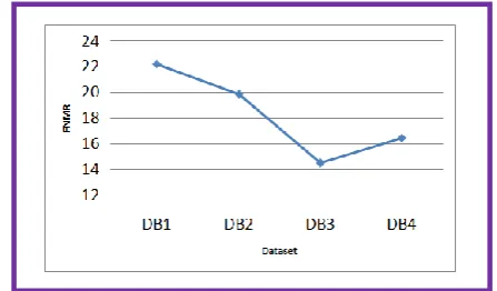
[image:6.595.317.518.188.234.2]The trend of the FNMR values of the four datasets is represented using the straight-line graph shown in Figure 8 as well as the column chart shown in Figure 9.
Table IV: FMR and FNMR Values for Dataset DB2
Statistics Value (%)
FMR 0
FNMR 19.85
Table VI: FMR and FNMR Values for Dataset DB4
Statistics Value (%)
FMR 0
FNMR 16.47
Fig 8: The trend of FNMR values for the four datasets Proceedings of the World Congress on Engineering 2014 Vol I,
[image:6.595.318.542.518.649.2] [image:6.595.55.263.526.586.2]The two figures show the pattern of FNMR values for the four datasets in decreasing order of 22.23, 19.85, 16.47 and 14.51 for datasets DB1, DB2, DB4 and DB3 respectively. This order established that the images in dataset DB3 are the best in terms of quality while those in dataset DB1 are the worst. In the overall for the four datasets, the proposed pattern matching algorithm identified fingerprints from different fingers by returning an average FMR of 0% while an average FNMR value of 18.26% is recorded as the extent to which the algorithm failed to match fingerprint images from the same finger. The average matching times in seconds and their trend for FNMR and FMR for the four datasets are presented in Table VII and the column chart of Figure 10 respectively.
Dataset DB3 has the lowest FNMR average matching time of 0.79 seconds and FMR average matching time of 0.93 seconds followed by DB4, DB2 and DB1 with average FNMR: FMR matching time of 0.86:0.89, 0.91:1.27 and 1.16:1.61 seconds respectively. The lowest average matching rate for dataset DB3 implies that the dataset has fewest numbers of minutiae points and consequently,
smallest number of computations. Similarly, the highest average matching times recorded for dataset DB1 indicate highest number of minutiae points in the images and consequently, the highest number of computations.
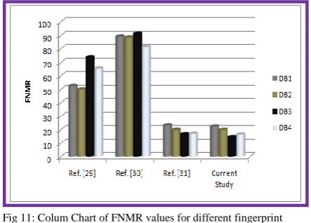
Table VIII presents the FNMR and FMR values for four different algorithms using the same dataset (FVC2002 fingerprint database). The algorithms presented in [29-31] were selected for comparison because they are among the most recent and just like the current study, they used FVC2002 fingerprint database for their system evaluations. In Table VIII, the original values obtained by the authors in [29, 30] are presented. However, we implemented the algorithm proposed in [31] under the conditions of experiments in this research to obtain the stated values.
[image:7.595.55.279.50.202.2]The superior performance of the proposed algorithm over the other algorithms is clearly exhibited with its lowest FNMR values for all the datasets. In addition, it is the only algorithm with an FMR value of zero for all the datasets. The column charts of Figures 11 and 12 is based on values presented in Table VIII and they illustrate the performance trend of the four algorithms with the current study having the lowest indicator heights for all datasets.
Table VII: Average Matching Time for the Four Datasets Dataset Average Matching time (sec)
FNMR FMR
DB1 1.16 1.61
DB2 0.91 1.27
DB3 0.79 0.93
[image:7.595.301.546.242.331.2]DB4 0.86 0.89
[image:7.595.52.291.407.668.2]Fig 9: Column chart of the FNMR values for the four datasets
TABLE VIII: FMR and FNMR for different algorithms
Ref. [29] Ref. [30] Ref. [31] Current Study
Data FNMR FMR FNMR FMR FNMR FMR FNMR FMR
DB1 52.58 0 89.3 1.7 23.07 0 22.23 0
DB2 50.03 0
88.6 3.7 19.91 0
19.85
0
DB3 73.75 0
91.2 2.4 16.68 0 14.51 0
DB4 65.24 .015 81.3 0.9 17.09 0.01 16.47 0
Fig 11: Colum Chart of FNMR values for different fingerprint matching algorithms
Fig 12: Colum Chart of FMR values for different fingerprint Fig 10: Column chart of the FNMR matching completion time for the four
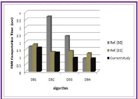
[image:7.595.318.542.435.775.2] [image:7.595.317.539.439.598.2]Table IX presents the obtained FNMR and FMR computations time in seconds in [30, 31] and the current study. We also implemented the original algorithm proposed in [31] under equal condition of experiments of the research to obtain the stated values.
For all the datasets, the proposed algorithm exhibited lower computation time, which confirms its superiority. A graphical representation of this is presented in the column charts of Figures 13 and 14.
Figure 15 shows the column chart of the average FNMR based on the data presented in Tables VIII for four different algorithms over the four datasets. Similarly, Figure 16 represents the column chart of the average FNMR and FMR computation times based on data presented in Table IX for the three algorithms. Visual inspection of the two Figures reveals superior performance of the proposed algorithm having recorded smallest heights in both cases.
V. CONCLUSION AND FUTURE WORKS
The implementation of a new fingerprint pattern matching algorithm has been presented. The algorithm used the relative distances between the minutiae and the core points. The algorithm hinged on the premise that irrespective of image orientation, each minutia point maintains constant distance with the core point for a given image size. The results obtained showed the effectiveness of the algorithm in distinguishing fingerprints from different sources with average FMR of 0%. However, the ability to match images from same source depends on the qualities of such images. Since the corruption levels vary across the used datasets, the algorithm yielded different FNMR values. The first dataset is mostly affected with FNMR values of 22.23% while the third dataset is least affected with FNMR value of 14.51%.
[image:8.595.314.547.46.217.2]The same order of performance was recorded for the FNMR and the average matching time over the datasets. A comparative review of the obtained FNMR, FMR and the computation time values with what obtained for some recently formulated algorithms over the same datasets revealed best performance for the proposed algorithm. Future research direction aims at the optimization of the proposed algorithm for further reduction in the FNMR values and the computation times.
TABLE IX: Matching Time in Seconds for Different Algorithms
Ref. [30] Ref. [31] Current Study
Dataset FNMR FMR FNMR FMR FNMR FMR
DB1 2 1.7 1.31 1.84 1.16 1.61
DB2 4 3.7 1.04 1.32 0.91 1.27
DB3 2 2.4 1.01 1.39 0.79 0.93
[image:8.595.51.272.55.213.2]DB4 3 0.9 0.91 1.23 0.86 0.89
Figure 15: Colum Chart of Average FNMR values for different fingerprint matching algorithms over the four datasets
Figure 13: Colum Chart of Computation time for FNMR values
for different fingerprint matching algorithms
Figure 14: Colum Chart of Computation time for FMR values for different fingerprint matching algorithms
Figure 16: column ChRT OF Average Computation Time for FNMR and FMr for different fingerprint matching algorithms over the four datasets
[image:8.595.310.548.263.408.2] [image:8.595.39.289.324.395.2] [image:8.595.46.282.458.626.2]REFERENCES
[1] Michael C. and Imwinkelried E. (2006): ‘A Cautionary Note about Fingerprint Analysis and Reliance on Digital Technology’, Public Defense Backup Center REPOR Volume XXI Number 3 T, pp7-9 [2] Nanavati S., Thieme M. and Nanavati R. (2002): ‘Biometrics,
Identifying Verification in a Networked World’, John Wiley & Sons, Inc., pp15-40
[3] Anil K. J., Jianjiang F and Karthik N. (2010): Fingerprint Matching, IEEE Computer Society, page 36-44
[4] McMurray H. N. and Williams G. (2007): ‘Latent Thumb Mark Visualization Using a Scanning Kelvin Probe’; Forensic Science International.
[5] Eckert W. G. (1996): ‘Introduction to Forensic Science’; New York: Elsevier
[6] FIDIS (2006): ‘Future of Identity in the Information Society’, Elsvier Inc.
[7] Salter D. (2006): ‘Thumbprint – An Emerging Technology’, Engineering Technology, New Mexico State University.
[8] Wayman J., Maltoni D, Jain A. and Maio D. (2005): ‘Biometric Systems’; Springer-Verlag London Limited
[9] Akinyokun O. C. and Adegbeyeni E. O. (2009): ‘Scientific Evaluation of the Process of Scanning and Forensic Analysis of Thumbprints on Ballot Papers’, Proceedings of Academy of Legal, Ethical and Regulatory Issues, Vol. 13, Numbers 1, New Orleans [10] Yount L. (2007): ‘Forensic Science: From Fibres to Thumbprints’
Chelsea House Publisher.
[11] Roberts C. (2005): ‘Biometrics’
(http://www.ccip.govt.nz/newsroom/informoation-notes/2005/biometrics.pdf)
[12] Iwasokun G. B., Akinyokun O. C., Alese B. K. &Olabode O. (2011a): ‘Adaptive and Faster Approach to Fingerprint Minutiae Extraction and Validation’. International Journal of Computer Science and Security, Malaysia, Volume 5 Issue 4, page 414-424. [13] Iwasokun G. B., Akinyokun O. C., Alese B. K. &Olabode O.
(2011b):’ A Modified Approach to Crossing Number and Post-Processing Algorithms for Fingerprint Minutiae Extraction and Validation’. IMS Manthan International Journal of Computer Science and Technology, Indian, Volume 6 Issue 1, pp1-9
[14] Shenglin Y. and Ingrid M. V. (2003); A Secure Fingerprint Matching
Technique, available online at
www.cosic.esat.kuleuban.be/publications/article-723.pdf.Accessed 23/01/2012
[15] Jianjiang F. (2008): Combining minutiae descriptors for fingerprint matching, Elsevier Pattern Recognition 41, page 342 – 352 [16] Yuliang He1,JieTian, Senior Member, IEEE, Liang Li 1, Hong
Chen1, Xin Yang (2005): Fingerprint Matching Based on Global
Comprehensive Similarity. Available online at
http://www.fingerpass.net/downloads/papers/Fingerprint%20Matchin g%20Based%20on%20Global%20Comprehensive%20Similarity.pdf. Accessed 21/08/2011
[17] Anil K. J. and Jianjiang F. (2011): Latent Fingerprint Matching, IEEE Transactions on Pattern Analysis and Machine Intelligence, Vol. 33, No. 1,, page 88-100
[18] Anil K. Jain, SalilPrabhakar, Lin Hong, and SharathPankanti (2000): Filterbank-Based Fingerprint Matching, IEEE Transactions on Image Processing, Vol. 9, No. 5,
[19] Jain A. K., L. Hong, S. Pankanti, and R. Bolle (1997): “An identity authentication system using fingerprints”. Proc. IEEE, 85(9):1365– 1388.
[20] Giuseppe P.e and Albert N. (2003): Fingerprint Matching Using
Minutiae Triangulation. Available online at
http://idisk.mac.com/geppy.parziale/Public/Papers/delaunay.pdf. Accessed 23/01/2012
[21] Xinjian C., Jie T., Xin Y. and Yangyang Z. (2006): An Algorithm for Distorted Fingerprint Matching Based on Local Triangle Feature Set, IEEE TRANSACTIONS ON INFORMATION FORENSICS AND SECURITY, VOL. 1, NO. 2, page 169-177
[22] Raymond T. (2003): ‘Fingerprint Image Enhancement and Minutiae Extraction’, PhD Thesis Submitted to School of Computer Science and Software Engineering, University of Western Australia, pp21-56. [23] Hong L., Wau Y. and Anil J. (2006): ‘Fingerprint image
enhancement: Algorithm and performance evaluation’; Pattern
Recognition and Image Processing Laboratory, Department of Computer Science, Michigan State University, pp1-30
[24] Iwasokun G. B., Akinyokun O. C., Alese B. K. &Olabode O. (2012): ‘Fingerprint Image Enhancement: Segmentation to Thinning’, International Journal of Advanced Computer Science and Applications (IJACSA), Indian, Vol. 3, No. 1, 2012
[25] Iwasokun G. B., (2012): ‘Development of a Hybrid Platform for the Pattern Recognition and Matching of Thumbprints’, PhD Thesis , Department of Computer Science, Federal University of Technology, Akure, Nigeria.
[26] López A. C., Ricardo R. L., Queeman R. C. (2002): ‘Fingerprint Pattern Recognition’, PhD Thesis, Electrical Engineering Department, Polytechnic University, Mexico.
[27] Maio D., Maltoni D., Cappelli R.Wayman J. L. and A. K. Jain, "FVC2002: Second Fingerprint Verification Competition," in 16th International Conference on Pattern Recognition, 2002, 2002, pp. 811 - 814.
[28] Perez-Diaz A. J. and Arronte-Lopez I. C. (2010): Fingerprint Matching and Non-Matching Analysis for Different Tolerance Rotation Degrees in Commercial Matching Algorithms, Journal of Applied Research and Technology, Vol. 8 No. 2, page 186-199 [29] Perez-Diaz A. J. and Arronte-Lopez I. C. (2010): Fingerprint
Matching and Non-Matching Analysis for Different Tolerance Rotation Degrees in Commercial Matching Algorithms, Journal of Applied Research and Technology, Vol. 8 No. 2, page 186-199 [30] Peer P.(2010): ‘Fingerprint-Based Verification System A Research
Prototype’, IWSSIP 2010 - 17th International Conference on Systems, Signals and Image Processing, Pages 150-153