Loading Behaviour of 90
˚
‘UREAD’ energy channels
R. Lupoi
aand F.H. Osman
bUniversity of Bath, Mechanical Engineering Department, Claverton Down, BA2 7AY, Bath, United Kingdom.
a [email protected] , b [email protected]
Abstract – Most engineering products are designed to either deliver or withstand a specific maximum force or level of energy. It is important however that the design of a structure or a machine incorporates an external or internal mechanism to overcome excessive loading, so as to reduce human discomfort and unsafe operations. Material elastic properties are exploited in most energy absorption devices but they have the disadvantage of generating rebound forces, in some cases comparable to those being absorbed.
This paper examines the validity of a new concept which has been implemented into a Universal Re-usable Energy Absorption Device – ‘UREAD’. A passageway made out of intersecting channels of a constant cross-sectional area is constructed inside the device where, upon the application of force, a piece of deformable material is allowed to flow through it. Energy is dissipated through intense shearing at each intersecting channels. Experiments were applied to devices characterized by two intersecting channels at 90˚. Passageways of square and circular cross sectional areas in the range of 60-100mm2 were tested using Silicon gum and lead. The results showed a typical pattern of deformation where the load remains almost constant after the initiation of plastic deformation through the channels. Material yield strength, billet length, and passage way cross-sectional area appear to be major contributors to the level of absorbed energy. The pattern of deformation under plane strain conditions was investigated by the Finite Element Analysis (FEA), and the predictions showed a yielding process that is dominated by internal shearing zones.
Key words: Energy absorption, UREAD, Severe plastic deformation, ECAE, Finite element analysis.
NOTATION
L1 billet length in the vertical channel
L2 billet length in the horizontal channel
b width of vertical channel
h width of horizontal channel
shear angle
v1 , v2 velocity components
F forming force
INTRODUCTION
particular viscoelastic materials, usually bonded between plates within the damper[5]. Devices embedded in structures were also developed such as the Tuned Mass Dampers (TMD)[6] and Tuned Liquid Dampers (TLD)[7], the absorption of energy is achieved by transferring some of the structural vibration energy to a small oscillator attached to the main structure. Each unit was tuned and designed to have the same natural frequency as the effective structure of the building. However, protection is certainly required also in other domains, such as personal safety. Nowadays, much of the development and innovations are in the personal safety of the user or operator. Body armours, made of different materials and composition [8,9], can be used as energy absorbers to protect the chest and other parts of the human body. Head protection is also a major research field, the standard design of a typical helmet[10] incorporates a rigid external shell, followed by an impact protection foam and an internal comfortable soft layer. In sport applications, legs are also subjected to severe loading conditions. Several shin and knee guards types were developed such as compressed air guards, fibreglass guards, Kevlar and plastic protections[11].
The variety of implemented devices available in the market, certainly ascertain that energy absorption is a cross discipline matter and has applications in many fields. However, researchers significantly concentrate on the design and development of energy absorption devices that could be implemented for safety in operational and personal protection. Some of the current methods may carry some disadvantages when absolute safety is concerned. These include the destruction of the protective device during the energy dissipation process, complexity of implementation, and the high demand on fashionable technologies that require innovative design, geometry and improved performance. In this paper, a novel methodology that has been exploited in the design of a Universal Reusable Energy Absorption Device (UREAD) is presented. Assessment of some of the device attributes are also studied and discussed.
‘UREAD’ DEVICES – CONCEPT AND DESIGN
It is common in the metal forming field to relate to the idea that metals, in general, can undergo large degree of deformation, either elastic or plastic. In order to design and develop energy dissipation devices that are based on the elastic properties of metals, one must consider the rebound of the input energy after impact. On the other hand, plastic deformation is irreversible, when used to dissipate high rate of energy, the material being deformed is usually distorted or permanently damaged. Osman [12] has invented a new device that has the potential of usability in almost any circumstances where mechanical shock is expected. The device is passive, i.e no rebounding and has the advantage of being reusable. The device is characterised by being a Universal Reusable Energy Dissipation Device (UREAD). The energy is dissipated by plastic shearing with 100% operational reliability for repeatability. The concept of the process is based upon forcing a deformable working material through a passageway of equal intersecting channels, the process in its elemental form is also known as angular extrusion.
Fig. 1a shows two concept of the angular extrusion process where material is forced to deform around the corner of intersecting channels. When an external load F is applied to the material, energy will be absorbed by plastic deformation. If the intersecting channels are of the same cross sectional areas then the entry and exit velocities are equal, but in different directions. In such a case the process can be reversed and further impacts may be repeated several times, with the potential of being used for infinite number of cycles. Ideally, a shearing process is immediately effected in the intersection zone on a shear surface at an angle α, as shown in Fig. 1a. In practice, a shearing zone develops as shown in Fig. 1b where the material before and after the shear zone moves with the velocities v1 and v2
respectively. The shearing process is demonstrated by the velocity discontinuity along the shear surface as shown in the velocity diagram, Fig. 1c. However, the energy level is limited by the allowable material travel, L1 and L2 for each channel respectively as shown in Fig 1a. In this case,
a) Angular extrusion b) Deformation pattern c) Velocity components
[image:3.595.78.506.429.697.2]
Figure 1. Deformation pattern in 90
˚
intersecting channelsIn practice, a closed passageway in which deformable material is forced to pass through intersecting channels is implemented to form a Universal-Reusable Energy Absorption Device (UREAD), capable of dissipating unwanted energy during severe impacts and crashes. The design of such devices incorporates a base that includes the channels and two punches, one for each end channel. Unit design is flexible with respect to the channels geometry and billet material. As a consequence, this new energy absorption technique reveals itself to be simple to use, with low cost and ease to manufacture. Also, energy absorption rates can be tailored to design demands.
‘UREAD’ DEVICES WITH 90˚ INTERSECTION
Experimental set-up
a) Square channels b) Circular channels
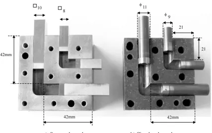
In order to examine the applicability of the UREAD technology, channels of different cross sections, geometry and lengths were designed. A tool was designed to include as many channels as possible. Fig. 2 shows two sectioned dies each containing two channels. Fig. 2a gives the details of two intersecting channels of 8mm and 10mm square cross sections, while Fig. 2b describes circular channels of 11mm and 9mm in diameters. In this investigation, all channels were of 90
˚
intersections. H13-tool steel was used to produce the experimental units. Punches were machined with a head of about 4mm to accurately fit into the channels with a shank of a smaller diameter to reduce the effect of friction between the punch and the die/channel walls. Each channel was tested independently for a full loading cycle. The energy dissipation devices of a circular/square cross sectional area, shown in Fig. 2, were experimentally tested using commercial pure lead (BS EN 12588) and high performance near-fluid Silicon HCR Gum, with trade name of RHODORSIL Gum 901. Lead is known to re-crystallise at room temperature and exhibits low frictional resistance. Simple compression tests were conducted on the working materials and the average yield strength of lead was found to be 11MPa. On the other hand, Silicon Gum is a viscous material with specific gravity of 0.97 and was found to have a yield stress of 60kPa. Lead billets were cast in special casting dies and were produced to the dimensions of the experimental square and circular channels. A hydraulic forging bench press, 80kN capacity, was used for all experiments. It is equipped with an in-house strain gauged load cell and a standard linear potentiometer, they were calibrated to measure the punch load and stroke respectively. The data were recorded using a real-time multi channel in-house Data Acquisition System equipped with PCI230 multi-channel I/O card and DC Instrumentation conditioning/amplifier card for each channel. HP VEE software was used to acquire the experimental data at a frequency of 50Hz. [image:4.595.107.513.403.537.2]Sequence of an operational cycle
Figure 3. Forward and reverse stroke procedure
‘UREAD’ UNIT CHARACTERISATION
In such a process characterisation may be split into two types. Geometric characterisation usually includes unit length, cross sectional area, channel profile, angle of intersection, and the dimensions of the channel secondary attributes, such as corners and edge radii. Operational characterisation includes the behaviour of the unit and workpiece material, lubrication, interface friction, loading profile and the capacity for energy absorption.
Channels of Circular Cross-Sectional Area
Experiments using Lead
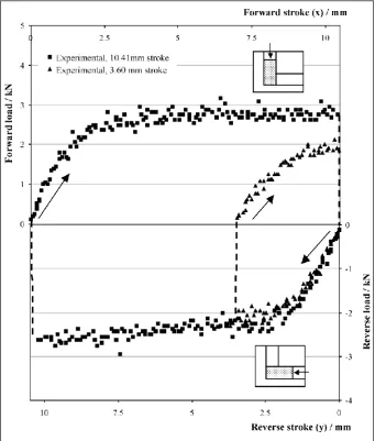
The two circular channels, shown in Fig. 2b, were tested using lead as a working material. Despite that a low coefficient of friction exists between lead and harden tool steel all billets material were further moisten with 10w40 commercial oil. The channels are of 9mm and 11mm diameters respectively. Two tests were carried out for each channel using two billets of different height. Fig. 4 gives the loading behaviour of the 9mm diameter intersecting channels represented by the load-displacement diagram. The billets used were 25.37mm and 18.78mm in length. The punch travel was 10.41mm for the longer billet and 3.60mm for the shorter billet.
[image:5.595.128.470.329.731.2]
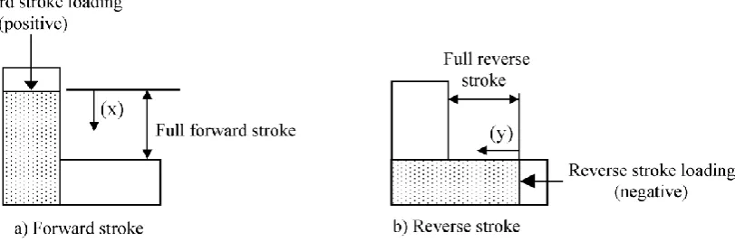
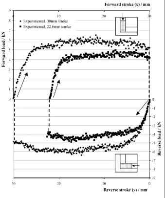
The characterisation of the load-displacement diagram of Fig. 4 is implemented on the basis of the sequence shown in Fig. 3. The forward stroke is the pass of the billet from the vertical channel to the horizontal channel. The loading in this case was taken as positive. When the workpiece material is pushed back in the reverse direction, from the horizontal channel to the vertical channel, the loading is taken as negative. However, the displacement for the forward stroke is shown on the upper most axis, while the reverse stroke is shown on the lower most axis. The forward and reverse results are linked together to show the full operational cycle.
[image:6.595.132.476.186.603.2]
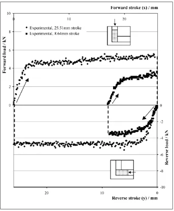
Figure 5. Experimental results for circular unit (11mm diameter)
diameter channel, Fig. 4, but with higher extrusion forces. The average load for the longest billet in this case is in the region of 5kN giving an average extrusion pressure of just under 5 times the material yield stress. However, the cross sectional area in this case is about 30% higher than that of the 9mm diameter test. Results also show higher loading requirements for longer billets. Shorter billets have smaller area of contact and hence frictional resistance for longer billets are much higher than those required for shorter billets. However, in 90
˚
side extrusion processes high hydrostatic pressure develops inside the cavity hence giving significance to the level of frictional resistance even at small coefficient of friction.
Channels of Square Cross-Sectional Area
Experiments using Lead
[image:7.595.130.470.325.731.2]The profile of the cross section of the intersecting channels in this test is a square; it differs from the circular channel in that the profile is discontinuous by the presence of the four corners of the square section. The dimensions of the cross section are 10x10mm, as shown in Fig. 2a. Two lead billets of heights 40mm and 32.6mm were used in this experiment. They were subjected to strokes of 30mm and 22.6mm respectively. Fig. 6 gives the loading results of a full cycle for the 10x10 square channel.
In this case also, the load displacement diagram initially increases until a steady continuous plastic flow is attained and hence average load remains almost constant. The average load for the longest square billet in this test is in the region of 6kN giving an average extrusion pressure of around 5.5 times the material yield stress. For both billets the load drops slightly near the end of the stroke, this could be due to the punch reaching the top of the intersection zone where deformation is more localised. In this case too, shorter billets required less loading requirements than taller billets.
Experiments using Silicon Gum
The square channel of 10x10mm, shown in Fig. 2a, was used to extrude the near-liquid polymeric material known as Silicon Gum. Fig. 7 shows the experimental punch force against the punch displacement for a full cycle and stroke of 25mm. For a viscous material the flow characteristics through the channel will depend upon many parameters such as the rate of deformation, the intensity of internal pressure, changes in viscosity due to the shearing mechanism. The diagram however shows that at the start of the process the loading requirements reached 25N after 2mm displacement. At the end of the full stroke of 25mm the maximum load was in the range of 40N.
Figure 7. Experimental results for square unit (10x10mm)
particular locations where interface friction or shearing between tool surfaces takes place. Also, the process appears to be characterised by an initial rapid increase in loading so as to overcome friction and material yielding. The results given by these tests demonstrated that devices employing the UREAD technology to dissipate unwanted energy are capable of performing a wide range of energy absorption levels if existed within a loaded structure. The external and internal profiles of the device could take any shape or geometry therefore it could be integrated into any structure or system easily. Alghamdi[13] studied the possibility of re-using thin circular conical aluminium elements in crash tests by fully inverting them from one test to another. Specimens failed after limited tests due to the cycle of high tensile and compressive straining of the elements. UREAD devices, tested several times, did not show any sign of failure due to the nature of the continuous compressive shearing process used inside the intersecting channels. The UREAD devices are true re-usable units because the processing route is repeatable without damaging the unit or the material being deformed.
FINITE ELEMENT ANALYSIS OF THE SHEARING ZONE
Deforming material through intersecting channels takes place by shearing at the intersection zones, visualisation of such a pattern is not easy but by the application of numerical analysis stresses distributions and deformation patterns can be visualised. A two dimensional model of intersecting channels was analysed by the Finite Element Analysis as implemented by the commercial package ANSYS. The process was simulated and studied at the onset of yielding. The model consisted of two intersecting channels of 10 and 5 mm width positioned in the vertical and horizontal directions respectively. The horizontal channel was considered as a free exit for the material in the vertical channel as shown in Fig. 8. The punch was assumed to be rigid and modelled by a line. An elasto-plastic material model was selected for the elasto-plastic deformation of the billet. Young’s modulus and the yield stress for the billet were 14GPa and 10MPa respectively. A coulomb contact friction was selected with a coefficient of friction of 0.2 at the interface between the channel sides and the billet material. Contact algorithm followed the Augmented Lagrange Method. Fig. 8 also shows the elemental subdivision used in the analysis.
Figure 8. Finite element model and elemental subdivision
Fig.10 shows contour plots of the shear stress distribution within the billet. At yielding, peak values of shear stresses existed in zones at the vicinity of the free exit, their values are comparable to the material shear yield stress. Also, as the billet height increases the maximum shear zone between the rigid portion of the billet, in the vertical channel, and the deforming material increases.
Figure 9. Plastic work distribution by Finite Element Analysis
CONCLUSIONS
A novel technology to dissipate unwanted energy was introduced and practical tests carried out to verify its applicable domains. The concept of a Universal Reusable Energy Absorption Devises (UREAD) was presented where a passageway was used to deform a workpiece material without changing its geometry. Devices with internal channels of circular and square cross sectional areas, in the range of 60-100mm2, were manufactured and used for testing lead and silicon gum. All channels were designed with a 90
˚
intersection profile. Experimental results showed that the load displacement diagram is characterised by an initial rapid increase in the loading requirements followed by a near steady state process where the loading requirements remain within a narrow band of values. Silicon gum required loads in the range of 30-40N to flow through 100mm2 cross sectional area, while lead absorbs a force of 6kN. However, the shearing mechanism in this process falls under the severe plastic deformation (SPD) operations and hence the punch pressure was in the range of 4-6 times the material flow stress for the cross sectional areas tested in this investigation. Finite Element Analysis also showed that the process is characterised by a deformation zone where intense shear bands were present at the intersection of the channels and maximum energy bands existed at 45˚
to the direction
of loading.
ACKNOWLEDGEMENT
The authors wish to thank Techsil Limited, Warwickshire, UK for
providing the Silicon gum
material used in the experiments.
REFERENCES
[1] T.T Soong, G.F Dargush, “Passive energy dissipation systems in structural engineering”, Wiley, 1996.
[2] William Henry Robinson, “Energy Absorber”, US Patent,(6,141,919), 2000.
[3] Douglas K Nims, Philip J. Richter, Robert E. Bachman, “The use of energy dissipation restraint for seismic hazard mitigation”, Earthquake Spectra, 9 (1993), 467-489.
[4] H. Mualla, Borislav Belev, “Performance of steel frames with a new friction damper device under earthquake excitation”, Journal of Engineering Structure, 24 (2002), 365-371.
[5] Zhao-Dong Xu, Hong-Tie Zha, Ai-Qun Li, “Optimal analysis and experimental study on structures with viscoelastic dampers”, Journal of Sound and Vibration, 273 (2004), 607–618.
[6] Nishimura, Yamada, Sakamoto, Kobori, “Control performance of active-passive composite tuned mass damper”, Smart Mater. Struct., 7 (1998), 637–653.
[7] H.F. Bauer, “Oscillations of immiscible liquids in a rectangular container: a new damper for excited structures”, Journal
of Sound and Vibration, 93(1)(1984), 117-133.
[8] D.P. Gonc¸alves, F.C.L. de Melo, A.N. Klein, H.A. Al-Qureshi, “Analysis and investigation of ballistic impact on ceramic/metal composite armour”, International Journal of Machine Tools & Manufacture, 44 (2004), 307–316.
[9] S. T. Cleevely, “Safe and sound-new developments in body armours”, Materials World, September 2002, 13-15.
[10] Luca Di Landro, Giuseppe Sala, Daniela Olivieri, “Deformation mechanisms and energy absorption of polystyrene foams for protective helmets”, Polymer Testing , 21 (2002), 217–228.
[11] Anthony C. Francisco, Roger W. Nightingale “Comparison of soccer shin guards in preventing tibia fracture”, The American Journal of Sport Medicine, 28 (2000), 2, 227-233.
[12] Fayek Osman, “Reusable Energy Dissipation Device”, Patent, W0 2004/044450 A1, 2004.