Abstract—Virtual building modeling became an increasingly urgent need for computer graphics, simulation, games, films and virtual reality. However, this is an exhaustive task and requires much more time and effort. There are many researches, which state this problem, but most of them concentrate on grammar-based generation. Grammar-based generation researches require more time to learn and are not suitable for non-qualified users. Our paper presents a new framework to generate automatic and extensive 3D solid building models procedurally relying on a set of methods called modules; these modules are offset, ellipse, L-system, smoother, polygon reduction, polygon division, transformation, and extrusion. Our building model can be created either automatically or semi-automatically. Each building model consists of some or all of our modules, these modules are specified either by an automatic model generator or by users to create a special model (using the wizard or writing an xml file). Model modules declare how the building footprints, floors and geometries will be generated. Our framework generates different building models using the same modules with different parameters’ values, while the modules remain small and simple, which means less time to learn and enables non-technical users to create wonderful solid building models. Our framework can generate trivial and non-trivial buildings’ types according to certain rules.
Index Terms—Procedural modeling, urban simulation, virtual city, L-system.
I. INTRODUCTION
Modeling a building is a great challenge in computer graphics; there is an urgent need for building modeling in virtual reality, in computer games, in movies, in simulation, and by architects. The buildings can be modeled either by hand or manually using specialized software such as CAD software; this requires much more time and effort from architects and planners to fulfill the modeling. Therefore, there is a growing need for modeling the buildings automatically, this operation is called a procedural modeling.
Design grammar is one of the used tools in building modeling. L_system is one of the design grammars that has achieved powerful results in plant modeling [Mêch
M. S. Author, is a professor at Helwan University, Helwan, EGYPT (e-mail: [email protected]).
A. K. Author, is a professor at Al-Shorouk Academy and computer graphics consultant, Cairo, Egypt (e-mail: [email protected]).
S.T. Author, is a master student at Helwan University, Cairo, Egypt (e-mail: [email protected]).
and Prusinkiewicz [1]; Prusinkiewicz and Lindenmayer [2]; Prusinkiewicz et al. [3]] and in the area of street modeling [Parish and M¨uller 2001 [4]]. Still, L-systems cannot easily be adapted to the modeling of buildings since they simulate growth in open spaces. An alternative grammar for buildings is shape grammar [Stiny 1975 [5]; Wonka et al. 2003 [6]; Muller et al. 2006 [7]]. The drawback of grammars is that they are usually limited to a specific class of models and they require a lot of training and time for experimenting.
Since the main problem of building modeling is the complexity of creating solid models in procedural modeling automatically especially by non-qualified users, this paper concentrates on procedural building modeling automatically by non-qualified users using few modules. Our framework will enable the user to generate the building models either fully automatically or using a customized model (a combination of modules are specified by the user using the wizard or writing an xml model file) for specific buildings.
This framework has the ability to generate interesting, variant and complex solid building models automatically using simple input, this input includes building coordinates and building’s attributes such as building type, building main side, ground floor type, etc. Each building will be generated according to its model modules. Model modules such as offset, ellipse, L-system substitution , transformations, smoother, polygon reduction, polygon division and extrusion. Our framework will produce solid faces of the façade (with no details), these faces carry attributes according to the user specifications ,these attributes will be important for generating façade details , but this is out of our scope.
Our paper will be structured as follows: After reviewing relevant previous work, Section III provides an explanation of our proposed framework and its components. Section IV presents model modules which should be specified by user to create models. Section V is the implementation. Section VI presents results and some examples of our models. Section VII presents the possible enhancement and plans for future work to our framework. Our conclusions are in Section VIII.
II. RELATED WORK
Procedural modeling was successfully introduced for
the natural phenomena especially for plants. Artistied Lindenmayer has proposed the formalism of lindenmayer systems, in short system. The central notation of L-system is the concept of rewriting where complex objects can be defined by replacing part00s of a simple initial object using a set of rewriting rules or productions, these productions are applied in parallel Prusinkiewicz and Lindenmayer [2]. There are many researches in plant modeling with L-system such as Przemyslaw et al [8]; Mêch and Prusinkiewicz [1]. L-system has been extended to include general computer simulation [Parish and Mŭller 2001 [4]] and self-sensitivity [Mêch and Prusinkiewicz [1]].
Building modeling researches fall in one of two approaches which are creating models using photographs and procedural modeling approach. Building modeling methods using photographs [Debevec et al [9]], videos and range scanning [Jepson et al [10]], etc, produce excellent models with high accuracy and reality, but they require clear and detailed images of the buildings, also they are quite labor intensive and can not be used to generate virtual cities or generate new building models. This approach is used to simulate existing buildings and cities, Whereas procedural modeling approach has the ability to create new building models and virtual cities. There are a few researches in this approach.
Parish and Muller propose a system called a CITY ENGINE [4] using a procedural approach based on L-system, which creates simple buildings. However, using L-system in city modeling still has less success than in plant modeling and it is more complex.
Wonka [6] generates buildings using a split grammar. Split grammar is a type of set grammar based on shape, it generates more realistic buildings, but this requires the users to learn this complex grammar and the rules of its database to set its attributes.
Greuter and Parker propose Real-time Procedural Generation of Pseudo Infinite Cities method [11], using this method, a building is built up, or more accurately, built down, in sections, each section is composed of a unique extruded floor plan. This research produce good buildings with simpler methods, but it has more focus on the real-time generation of a city.
Pascal and Wonka present a grammar-based solution to generate detailed building [7]. They generate mass models of buildings using union of volumetric shapes and transformation operations.
III. PROPOSED FRAMEWORK
There are many researches, which state procedural building-modeling problem, but most of them concentrate on grammar-based solutions Wonka [6] , Pascal and Wonka [7], and the solid models generation process is
constructed as a union, scaling, rotation, and translation of volumetric shapes.
Our approach concentrates on solid models generation both automatically and semi-automatically. In our framework, the automatic building model generation means that the model will be generated fully automatically using our system according to the building attributes, and Semi- automatically means that the user will specify (select ) the modules of the model.
Our framework has large databases, these databases are:
A. Buildings’ Models Database :
For each building’s model , we save its modules and its faces. Accessing model’s modules from Database can generate a different model due to the randomness used in each module (parameters), but accessing model’s faces generates typical models of the saved one.
B. Buildings’ Rules Database:
This database contains the rules of some building types. These rules help the automatic model generator to generate new buildings’ models.
C. L-System Production Rules Database:
This database contains the L_system production rules, axioms, and some other attributes. This database helps the L-system generator to generate L-system curves.
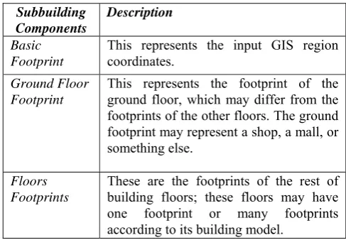
Our approach relies on the principle that each building has a set of floors and each floor has a footprint. It is not necessary that each floor’s footprint should be unique; all floors may have the same footprint. These footprints will be extruded to construct the building’s solid model with its faces. Each building is divided into one (simple) or more sub buildings (complex building). Table Ι shows subbuilding components.
Table Ι: SubBuilding Components
Subbuilding Components
Description
Basic Footprint
This represents the input GIS region coordinates.
Ground Floor Footprint
This represents the footprint of the ground floor, which may differ from the footprints of the other floors. The ground footprint may represent a shop, a mall, or something else.
Floors Footprints
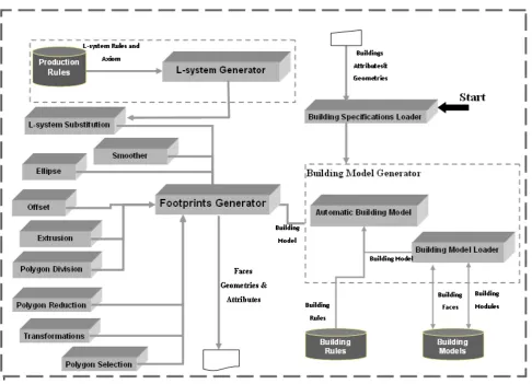
[image:2.595.304.548.551.720.2]Figure 1: Framework components
The framework components will interact with the following scenario:
The first component invoked in our system is buildings specification loader. This component is responsible for loading the building’s region geometries and its sides’ attributes for example, is it one of the main façade sides? if yes, then what is its façade side number ? Etc. In addition, it is responsible for loading building’s attributes such as simplicity, name, model generation type, etc. Generation type attribute value can be one of the following values:
• Automatic: means that the building model will be generated using our system. So, the automatic model generator component will be invoked. • Database: this attribute value requires the model
name attribute to be specified (model name should be included in our building model database). Building model loader is responsible for loading the saved model.
• Manual: the user will construct his building model by selecting the suitable modules using our system wizard or specifying the name of xml file that contains the building model modules, Therefore, building model loader will be invoked. After that footprints generator will be invoked to generate solid models that include faces geometries and their attributes, which will be useful in façade generation. According to the building model’s modules, Footprint generator will call the following components: L-system substitution, extrusion, smoother, polygon division, polygon selection, polygon reduction, and transformations.
IV. FRAMEWORK COMPONENTS
A. Building Specifications Loader
This component is responsible for loading the input region coordinates and building attributes.
B. Building Model Generator
This component includes the followings: 1) Automatic Building Model Generator
This component is responsible for generating building models automatically according to the attributes of the building such as building type. The generated building model can be one of the followings:
Selected Model
This model is selected and loaded from building models database, according to the building attributes by the building model loader. But in this model type , only model faces will be loaded.
Modified Selected Model
This model is selected and loaded from building models database according to the building attributes. But in this model type, model modules are loaded and then are modified by the automatic model generator.
Generated Model
The model modules and their parameters values will be set according to this building type rules that are specified in the building rules database. The following examples declare some of buildings rules.
Villa Rules Example:
• Basic footprint: - must have offset module with offset area parameter ranging from 40 to 60 percent to represent the garden of the villa.
• Extrusion module should have a height parameter of >3m.
• It should have L-system module and L-system smoothing module.
Popular Buildings:
• It can include Offset module with the offset area parameter ranging from 0-20 %
• Can’t include other modules, except extrude module.
2) Building Model Loader
This component is responsible for loading and saving building model modules and building model faces. Building model loader can load building model from:
• Building model database
• XML building model file which is edited by the user to create his own special model.
• System wizard.
C. L_system Generator
An L-system is a parallel string rewriting mechanism based on a set of production rules. Each string consists of a set of symbols with associated numerical parameters. Simulation begins with an initial string called the axiom, and proceeds in a sequence of discrete derivation steps. In each step, rewriting rules or productions replace all modules in the predecessor string by successor modules.
L-system Generator generates L-system curves according to the selected production rules, axioms, and a suitable number of iterations saved in the production rules database. Selected production rules may be selected by the user or randomly. In addition, it can generate L-system curves by applying more than one type of curves production rules to generate extensive L-system curves.
D. L-System Footprint Substitution
This component is responsible for Substituting the specified footprint sides (specified by the user or randomly) of the current footprint with the curves generated by L-system generator.
E. Footprint Generator
This component generates building footprints and faces with the help of the other components. It is considered the main component in the footprint generation process, which is responsible for calling the other components (such as polygon division ,L-system substitution, polygon reduction ,polygon selection, transformations ,ellipse, offset, and smoother component ) according to the building model modules that is passed from building model generator.
F. Ellipse Component
This converts a current footprint that can be a square or triangle into an n-side polygon .It is mostly used in basic footprint. This component is based on the ellipse algorithm, which states that any rectangle/square has in-ellipse; the in-ellipse is the largest ellipse that will fit inside the rectangle and touch each side of the rectangle in just the middle of it .Our ellipse algorithm states that extensive polygon types can be generated from the ellipse Where the polygon can be inside or outside the ellipse, convex or non-convex, and simple or complex polygon, all of the resulted polygon types depend on parameters justification in the algorithm. The ellipse is represented parametrically in equation (1),(2).
Θ
=
W
cos
x
(1)H: half the rectangle height Θ : <= 2 ∏
In our algorithm, we will add a and b parameters to the equation (1) ,(2) to produce equation (3),(4) .
x
=
W
a
cos
Θ
(3)
y
=
H
b
sin
Θ
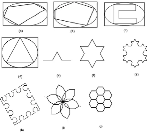
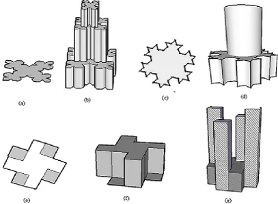
(4) a and b values will determine if the vertices inside or outside the ellipse. For example: if a <1 and b < 1 then the vertex will be inside the ellipse, and if a >1 and b >1 then the vertex will be outside the ellipse. We declare some examples in figure.2. (a),(b),(c),(d).Figure2: (a), (b), (c), and (d) generated polygons from ellipse algorithm. (e) L-system Curve. (f) is the triangle of figure(d) is substituted with L-system curve that is shown in figure(e), (g) represents figure (f) is substituted with L_system curve that is shown in figure (e). (h), (i), and (j) some generated L_system Curves.
G. Polygon Division
This is responsible for dividing the footprint into smaller pieces using polygon division and polygon triangulation algorithms.
H. Transformations
Transformations include transformation operations such as scale, rotate and translate operations.
I. Polygon Selection
This is responsible for selecting triangles groups, which depends on the input parameters:
• Number of groups
• Estimated area of each group.
• This returns the contour of the selected groups.
J. Polygon Reduction
This is responsible for eliminating a piece of the footprint. This component calls polygon selection component and then eliminate the selected group (selected triangles) with a specified area.
K. Smoother
This is responsible for converting sharp curves (opened or closed curves) into smoothed ones [Przemyslaw et al [12], [13]. The curve may be L-system curve or a polygon (considered as a closed curve).
L. Offsets
[image:5.595.53.287.230.444.2]This offsets the polygon sides to inside according to the offset area parameter. A typical copy of the footprint will be generated. This module is often used in the basic footprint to leave an empty area around the building to be garden, pavement or etc. Figure.3. presents polygons with offsets .
Figure 3: Offset Algorithm
V. BUILDING MODEL MODULES
In this section, we will introduce the modules that create the solid building model. Model can be edited (or specified) by the user. If the user does not specify the module parameters values, then our system will use its default values.
We have two types of modules:
• Basic modules: are the elementary modules that any building model will be converted to .
• Assistant modules: are virtual modules that make our model more readable. These modules are translated into the basic modules to be implemented or used for readability only.
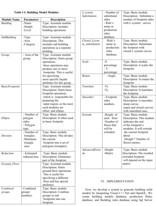
Table ΙΙ: Building Model Modules
Module Name Parameters Description Building -Name
-Simple -Level
Type: Assistant module. Description: includes building operations.
SubBuilding -Type -Area -Category
Type: Assistant module. Description: This includes sub building operations as a separate building.
Group - Area of the group.
Type: Assistant module Description: Starts group operations,
these operations may produce one or more footprints. This is useful for specifying
more specific façade attributes for this group.
BasicFootprint Type: Assistant module
Description: Starts basic footprint operations which is responsible for preparing the
input region, so the most used modules are offset, and ellipse.
Ellipse
- Number of polygon sides. - Polygon type.
Type: Basic module Description: It often used in basic footprint.
Division
- Number of triangles. - Minimum triangle area.
Type: Basic module Description: This divides the current
footprint into a set of polygons (triangles).
Reduction - Estimated reduced area
Type: Basic module Description: Eliminates part of the footprint.
Ground_Floor Type: Assistant module
Description: Starts ground floor operations. This is useful for specifying a different floor and has special attributes. Combined groups - Combined groups’ numbers.
Type: Basic module Description: Combine groups or sub footprints into one footprint.
L-system Substitution
- Number of substituted sides - Rule’s name in production rules database.
Type: Basic module Description: Substitute a number of footprint sides with L-system curves.
Closed_Lsyste m_substitution -Rule’s name in production rules database.
Type: Basic module Description: Substitutes the footprint with closed L-system curves.
Scale -X
percentage - Y percentage
Type: Basic module Description: it scales the footprint.
Rotate - Angle. Type: Basic module Description: It rotates the footprint.
Translate -Tx -Ty
Type: Basic module Description: It translates the footprint.
Smoother - Footprint sides numbers.
Type: Basic module Description: it smoothes sharp curves
(open and closed curves) with smoothed ones . Extrude -Height of
each floor -Number of floors that will be extruded .
Type: Basic module Description: This module indicates the end of the footprint‘s modules. It will extrude the current footprint about
(Height * Number of floors) meters.
AdvancedExtru de
-Height -Matrix
Type: Basic module Description: The resulted extruded footprint will depend on the input matrix.
VI. IMPLEMENTATION
[image:6.595.48.555.63.734.2]database. In our System, We enable the user to create his building model using our system wizard :
• Manually :the user will select his xml model file (so, we create xml schema file).
• 2-Automatically : our automatic building model generator will generate the model.
• Semi-automatically: user will select building model from building models database.
VII. RESULT
In our system, we construct our building models database using Sql server, it includes the modules and the faces of the desired buildings models. The user has the ability to save the desired models produced from our system. We construct production rules (L-system rules) database using Sql server, which includes the selected L-system production rules that will be more suitable for buildings. Also in our framework, we have building rules database. These rules are helpful for the automatic model generator to create the generated model according to certain rules. To keep our system fast, we develop our system with Visual C++ and OpenGl.
We present some building models’ examples that are written in xml files. The following examples represent samples of our system results:
• Skyscraper Model Example
<?xml version="1.0" encoding="utf-8" ?> <Building Name="specialTower" Level="high" Simple=”true”>
<SubBuilding type=”skyscraper” category=="residential" > <Basic_Footprint>
<Offset_Algorithm /> </Basic_Footprint> <Ground_Floor>
<Extrude floorHeight="4" numberOfFloors="1" /> </Ground_Floor>
<Floors> <Division /> <Reduction />
<Extrude floorHeight ="3" numberOfFloors ="20" /> <Division />
<Reduction area="40" />
<Extrude height="3" number="20" /> </Floors>
</SubBuilding> </Building>
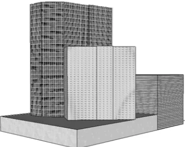
Figure 4 shows the output of the above example.
• Mall Model Example (Commerical Building)
<?xml version="1.0" encoding="utf-8" ?>
<Building Name="grandMall" Level="high" simple=”true”>
<SubBuilding type=”mall” category="commercial"/> <Basic_Footprint>
<Offset_Algorithm area="0.10" /> </Basic_Footprint>
<Ground_Floor>
<L_system number_of_sides="2" rule_name="halfCircle" /> <Extrude floorHeight="6" number_of_floors="1" /> </Ground_Floor>
<Floors>
<L_system_scale percentage="0.8" />
<Extrude height="6" number_of_floors="2" /> </Floors>
</SubBuilding> </Building>
Figure 5 declares mall model generation steps .
• Complex Mall Model Example <?xml version="1.0" encoding="utf-8" ?>
<Building Name="complexBuilding" Level="high" Simple=”false”>
<SubBuilding area="0.30" Type=”Building” Category="administrative"> <Floors>
<Extrude floorHeight="4" Number_of_floors="4" /> </Floors>
</SubBuilding>
<SubBuilding area="0.70" Type="residential"> <Basic_Footprint>
<Extrude floorHeight="4" numberOfFloors="1" /> </Basic_Footprint>
<Floors>
<Extrude height="4" number="4" /> <Group area="0.30">
<Extrude floorHeight="4" Number_of_floors="6" /> </Group>
<Group area="0.35"> <Extrude floorHeight="4" Number_of_floors="10" /> </Group>
</Floors> </SubBuilding> </Building>
• L-System Examples
We show some buildings’ examples which rely on l-system curves (l-l-system substitution module) in figure 7.
VIII. FUTURE WORK
We will extend our framework components to include façade generation component, which will be able to generate the façade with all its details using GPU.
IX. CONCLUSION
In this paper, we have presented a new framework for the automatic generation of extensive 3D solid building models procedurally relying on a set of simple methods called modules; these modules are offset, ellipse, L-system, curve smoother, triangulation, polygon reduction, polygon division, transformations, and extrusion modules. The main contribution of our paper is the automatic generation of the building with low user contribution and without dipping the user with technical details. Because our framework can generate the building fully automatically. Therefore, our framework will be more suitable for non-technical users, especially when we develop our system to be able to generate the building using the wizard and the user will be able to modify and cancel the intermediate steps of model generation. In addition, our framework has the ability to generate special, extensive and fantasy models using our modules especially L-system module.
ACKNOWLEDGMENT
Before and after anything praise is to God. Special thanks to Hany Mohamed for his help and support to complete this paper.
REFERENCES
[1] Mêch R., and Prusinkiewicz, “Visual Models Of Plants Interacting With Their Environment,” in proc. 23rd Annual Conference On Computer Graphics And Interactive Techniquess, new york ,1996 , pp. 397-410.
[2] Przemyslaw Prusinkiewicz and Aristid Lindenmayer.The algorithmic beauty of plants. Springer-Verlag New York, Inc., New York, USA, 1996.
[3] Przemyslaw, Prusinkiewicz, M. James, and R. Měch, “Synthetic topiary,” in proc. the 21st
Annual Conference On Computer Graphics and Interactive Techniques, New York, 1994, pp. 351-358.
[4] Parish, Muller, “Procedural Modeling of Cities,” in proc. 28th Annual Conference On Computer Graphics And Interactive Techniques, New York, 2001, pp. 301-308.
[5] Stiny, G. 1975. Pictorial and Formal Aspects of Shapes and Shape Grammars. Birkhauser, Basel, Switzerland.
[6] Wonka, p., Wimmer, m., Sillion f., and Ribarsky, w, "Instant Architecture," in proc. ACM Siggraph, 2003, 669- 677.
[7] Pascal Muller, Peter Wonka, Simon Haegler, Andreas Ulmer, and Luc Van Gool, "Procedural modeling of buildings. ACM Trans. Graph., 25(3):614-623, 2006.
[8] Przemyslaw, Prusinkiewicz, M. James, and R. Měch, “Synthetic topiary,” in proc. the 21st
Annual Conference On Computer Graphics and Interactive Techniques, New York, 1994, pp. 351-358.
[9] Debevec, P. E., Taylor, C. J., and Malik, J, “Modeling And Rendering Architecture From Photographs: A hybrid Geometry- And Image- Based Approach,” ,” in proc. 28th Annual Conference On Computer Graphics And Interactive Techniques, 1996,pp. 11-20.
[10] Jepson, w., Liggett, r., and Friedman,"Virtual Modeling Of Urban Environments," in proc. Computer Graphic International, 1997.
[11] Greuter S., Parker J., Stewart N., AND Leach G, "Real-time Procedural Generation of `Pseudo Infinite' Cities," in proc. the 1st International Conference On Computer Graphics And Interactive Techniques in Australasia and South East Asia , New York, 2003, pp 87-ff.
[12] Przemyslaw Prusinkiewicz, Faramarz F. Samavati, Colin Smith, Radoslaw Karwowski, "L-system Description of Subdivision Curves,". International Journal of Shape Modeling, vol 9, 2003, pp. 41-59.
Figure 4: Shows Skyscraper model steps.
Figure 5: Mall model steps.
[image:9.595.207.389.561.706.2][image:10.595.90.498.236.534.2]
Figure 7: Generated Buildings rely on l-system curves.