Exploring haptic feedback for robot to human
communication
GHOSH, Ayan, PENDERS, Jacques <http://orcid.org/0000-0002-6049-508X>,
JONES, Peter <http://orcid.org/0000-0002-1225-0192>, REED, Heath
<http://orcid.org/0000-0003-2615-3315> and SORANZO, Alessandro
<http://orcid.org/0000-0002-4445-1968>
Available from Sheffield Hallam University Research Archive (SHURA) at:
http://shura.shu.ac.uk/8520/
This document is the author deposited version. You are advised to consult the
publisher's version if you wish to cite from it.
Published version
GHOSH, Ayan, PENDERS, Jacques, JONES, Peter, REED, Heath and SORANZO,
Alessandro (2014). Exploring haptic feedback for robot to human communication. In:
SHARKEY, Paul, PARETO, Lena, BROEREN, Jurgen and RYDMARK, Martin, (eds.)
The 10th International Conference on Disability, Virtual Reality and Associated
Technologies, Proceedings. Reading, University of Reading, 309-312.
Copyright and re-use policy
Exploring haptic feedback for robot to human communication
A Ghosh
1, J Penders
1, P Jones
2, H Reed
3, A Sorranzo
41Materials and Engineering Research Institute, 2The Department of Humanities,
3Art and Design Research Group, 4The Department of Psychology, Sociology and Politics,
Sheffield Hallam University, Sheffield, UNITED KINGDOM
[email protected], {j.penders , p.e.jones, h.reed, a.soranzo}@shu.ac.uk
www.shu.ac.uk
ABSTRACT
Search and rescue operations are often undertaken in low-visibility smoky environments in which rescue teams must rely on haptic feedback for navigation and exploration. The overall aim of our research is to enable a human being to explore such environments using a robot. In this paper we focus on creating feedback from a robot to a human. We describe our first designs and trials with vibration motors. The focus is on determining the potential use of vibration motors for message transfer and our trials reflect whether different messages can be discriminated. We describe the testing procedure and the results of our first tests. Based on these results, we conclude that close spatial arrangement of the motors blurs individual signals.
1. INTRODUCTION
Search and rescue operations in fire incidents, are undertaken only when the ground is relatively passable (Penders et al, 2011); the major problem however is that the environment is smoke-filled and noisy. Lack of visual and auditory feedback make rescue teams rely on haptic feedback for navigation and exploration. Navigation concerns finding the way, while exploration involves exploring the environment and finding possible victims. Robots with a range of sensors on board might be helpful for such conditions. In addition, there are also everyday situations where vision and audibility are low, for instance, a visually impaired person trying to walk along a street.
An early work on robotic navigation assistance to the visual impaired is described in Tachi et al. (1983). They developed a guide-dog robot for the visually impaired, which guides the person. The robot tracks the handler using active sonar, and the handler wears a stereo headset, which provides coded aural feedback to notify whether the handler is straying from the path. There are no means to communicate with the robot, and the handler must learn the new aural-feedback code: the robot serves as a mobile beacon that communicates with the headset. More recently, Allan Melvin et al, (2009) developed a robot guide to replace a guide dog. We described a robotic guide in (Ghosh et al, 2014), the emphasis is on how well a person follows the robot; however the human does not have any control over the robot and thus cannot explore.
There is quite a difference between guidance and exploration. Guidance is limited to the robot leading the person or handler. This setting presupposes that the robot does the way-finding and the person just follows. Exploration concerns investigating the direct but yet unknown environment. As there is no-visibility, exploration has to rely on active haptic sensing. A widely used device for haptic exploration is a white cane as intended for the visually impaired. Inspired by this, Ulrich and Borenstein (2001) developed the GuideCane. It is a cane like device running on unpowered wheels, it uses Ultra Sound to detect obstacles. The handler has to push the GuideCane - it has no powered wheels- however it has a steering mechanism that can be operated by the handler or operate autonomously. In autonomous mode, when detecting an obstacle the wheels are steering away to avoid the obstacle. Obviously the feedback to the human remains implicit: the handle is the medium.
operating it. The final aim is to use a powered robotic device. However, a major issue with a powered robotic device is that there is no room for active haptic sensing by the human and the feedback to the handler has to be made explicit. In this paper we focus on creating feedback from a powered robot to the handler. We describe our first designs and trials with vibrating motors. At this stage the focus is on determining the potential of a set of vibration motors for message transfer; the trials investigate whether different messages can be discriminated.
Figure 1. Metal disc fixed with a fixed handle.
2. FEEDBACK DEVICE
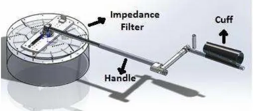
[image:3.595.170.424.367.479.2]Our design incorporates a robot with an impedance filter, which is connected with a handle to the handler. Figure 2 shows the impedance filter - a skirt-like structure - which sits on top of the robot (Janani et al, 2013). The figure also shows the handle, the physical interface between robot and the handler. Our previous work (Ghosh et al, 2014) has reflected on various aspects of the handle design. While encountering an obstacle, the skirt is displaced. The displacement is measured (using Cable Reel Transducers); these measurements need to be transformed into some sort of a haptic input to the handler. Defining and designing the input signal for the human handler is our current objective.
Figure 2. The handle (with feedback cuff) and the impedance filter.
We apply six vibrating motors, which are fixed on a wearable cuff (as shown in Figure 4) attached to the crutch-like part of the handle (as shown in Figure 2) . The motors vibrate for short periods (3-5 seconds) on the lower arm of the handler. The motors are individually controlled; however, all motors operate at the same frequency and intensity. They are connected through a microcontroller and operated using a software interface developed in Labview.
3. TESTING PROTOCOL
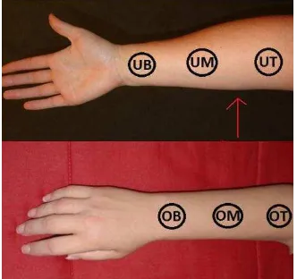
Figure 3 shows a person wearing the cuff on the lower arm. Our first question is whether subjects are able to distinguish which individual motors are activated; in addition our aim is to study whether different combinations of concurrent vibrating motors are recognisable. After one or more vibration motors were turned on for 3-5 seconds, the subjects were asked to report on the positions of the motors, by pointing out the options shown in the picture (Figure 3 right). To make it easier to understand, we named the positions as following: motors close
to the wrist, Under Arm Bottom (UB) and Over Arm Bottom (OB), in the Middle as Under Arm middle (UM)
and Over Arm Middle (OM)and close to the Elbow as Under Arm Top (UT) and Over Arm Top (OT), refer to
Figure 5. Every subject was given noise cancelling ear protectors to neutralise all possible auditory cues.
Six subjects, aging between 22 and 55 without any medical condition, took part in our experimental study.
activated, but only one at the time. In the second trial set two motors are activated concurrently but in varying patterns and in the third set three motors are activated in varying patterns. The final session consists of a mix of single, double or triple motor activations in a random order.
[image:4.595.134.463.108.251.2]
Figure 3. (Left) The cuff on trial and the trial’s feedback display. (Right) The picture placed in front of the subjects for pointing out the positions.
Figure 4. Feedback cuff. Figure 5. Position of the vibration Motors.
4. RESULTS
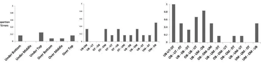
Figure 6 shows the errors subjects made in identifying the specific motors for the first three trial sets. The figures show motor positions on the horizontal axis; the vertical axis shows the proportion of errors (0-1) made when the respective motors were activated. Figure 6 left, shows the error proportions with single vibrating motors, the figure in the middle shows error proportions with two vibrating motors and the figure on the right shows error proportions with three vibrating motors. We notice that there is an increase in the number of errors as the number of vibrating motors increases. It is evident that the subjects were most accurate in determining the positions of vibrations when only a single vibration motor was turned on.
Average proportions of errors for the 3 different trial sets were as follows:
Set 1 (single vibrating motor; 6 trials): 0.125 (0-1)
Set 2 (2 motors vibrating concurrently; 12 trials): 0.22 (0-1)
Set 3: (3 motors vibrating concurrently; 12 trials): 0.40 (0-1)
These results indicate the increasing difficulty in accurate identification of vibrating motor(s) over the three sets.
[image:4.595.331.497.286.442.2] [image:4.595.83.281.310.420.2]Figure 6. Proportion of errors, single (left); double(middle);triple(right).
For the second set of trials, error rates were higher than for the first set but still rather low. A repeated one-way ANOVA measure on the arc sin transformation showed no significant difference in proportion of errors across the twelve trial conditions (F(5,11)= .73; p. = 0.7) involving pairs of concurrently vibrating motors.
In the third set of trials in which three motors were activated concurrently, the error rates are high. Furthermore, the one-way ANOVA (F(5,11)= 3.89; p. < 0.01) showed a significant difference in proportion of errors across the twelve trials. It would appear, then, that the task becomes much more challenging with three vibration motors switched on and also that some of the triple-combinations are more readily identifiable than others, although the precise reasons for this extra level of difficulty are not clear. Anecdotal evidence suggests that identification difficulties may be associated with distribution or proximity of the motors on the arm but we were unable to establish this from our present data.
5. CONCLUSIONS and FUTURE WORK
The findings of the experimental trials raise a number of issues that need to be taken into account for future re-design of the cuff and the message-sending configurations of vibrating motors. The trial data show that subjects were easily able to distinguish when individual vibration motors were activated but that the difficulty of the task increased when motors were combined. Combinations of three motors, in particular, were especially difficult to identify accurately.
For these reasons, present work is focussed on the use of a cuff with only four vibration motors (two on each side) which will be used either singly or in pairs to transmit messages. Future experiments will also investigate whether specific signatures in vibration frequency and intensity for each motor may improve recognition.
A next
step is to define and design feedback signals (a sort of haptic alphabet) that correspond with displacements of the impedance filter.6. REFERENCES
Ghosh, A, Penders, J, Jones, P, and Reed, H, (2104), Experience of following a Robot using a Haptic Interface without Visual Feedback, IEEE Ro-Man, Edinburgh (in press).
Janani, A, Holloway, A, Reed, H, and Penders, J, (2013), Design of a Mechanical Impedance Filter for Remote Haptic Feedback in Low-Visibility Environment, TAROS, Oxford.
Jones, P, Ghosh, A, Penders, J, and Read, H, (2013), Towards human technology symbiosis in the haptic mode, In: International Conference on Communication, Media, Technology and Design, Famagusta, North Cyprus, 2-4 May 2013. 307-312.
Melvin, A, Prabu, A, Nagarajan, B, Bukhari, R, and Illia, (2009), ROVI: a robot for visually impaired for collision- free navigation, Proceedings of the International Conference on Man-Machine Systems (ICoMMS).
Penders, J, Alboul, L, Witkowski, U, Naghsh, A, Saez-Pons, J, Herrechtsmeier, S, and El-Habbal, M, (2011), A robot swarm assisting a human firefighter, Advanced Robotics, 25:93-117.
Tachi, S, Mann, RM, and Rowell, D, (1983), Quantitative comparison of alternative sensory displays for mobility aids for the blind, IEEE Trans. Biomedical Engineering, vol. 30, no. 9, pp. 571–577.