BETTIN, Jorn and CLARK, Anthony <http://orcid.org/0000-0003-3167-0739>
Available from Sheffield Hallam University Research Archive (SHURA) at:
http://shura.shu.ac.uk/11920/
This document is the author deposited version. You are advised to consult the
publisher's version if you wish to cite from it.
Published version
BETTIN, Jorn and CLARK, Anthony (2009). Gmodel, a language for modular meta
modelling. In: Australian Software Engineering Conference, KISS Workshop, Gold
Coast, Australia, 14-17 April 2009.
Copyright and re-use policy
See
http://shura.shu.ac.uk/information.html
Sheffield Hallam University Research Archive
JORN BETTIN, TONY CLARK
It is increasingly recognised that domain specific modelling languages hold the key for improving productivity and quality in software design, development, configuration, inter-operability, an operation. Although there are a number of languages that can be used for specifying the abstract syntax of a modelling language, none of these languages provides optimal support for modular specifications of sets of complementary modeling languages. Gmodel is a language that has been designed from the ground up for the purpose of meta modelling. It addresses modularity and extensibility as primary concerns, and is based on a small number of language elements that have their origin in graph theory.
1. Introduction
ToDo ◮a general introduction to topic, introduce terms DSL etc...◭
Designing and implementing domain specific modelling languages for industrial use is only practical if the tooling used for language design and implementation is sufficiently robust and easy to use. At this point in time (2009), the number of tool chains that can be used for language design and implementation is growing, but easy integration of languages that have been developed with different tool kits is not yet a reality.
ToDo ◮cite some examples of interoperability problems◭
ToDo ◮an example that motivates the need for tool chains and interoperability...◭
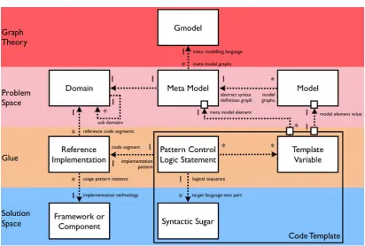
The design of a domain specific modelling language involves the specification of an abstract syntax based on familiar and established domain terminology, the design of one or more concrete syntaxes, and the design of ergonomic model editors for each of the concrete syntaxes. Concrete syntax is mainly relevant for humans and model editor design, whereas abstract syntax is also relevant for all other tools (beyond editors) that process model-based artefacts.
Interoperability hinges on the ability of tools in a tool chain to exchange model-based artefacts, which entails the ability to read modelling language definitions and models. In this context a shared abstract syntax for articulating language definitions is essential, and consequently there is a need for a meta language that can serve as the glue in model-based tool chains.
Experience shows that software vendors want to - and need to - compete in terms of implementations. No single meta language can address all interoperability issues. Therefore, in order to be relevant, any shared meta language must be extensible, and
Figure 1. Gmodel in the context of the development of domain specific languages
should only be viewed as the substrate on top of which practical interoperability solutions can be built - and not as the ultimate solution for all interoperability needs.
Choosing graph theory as the main source of terminology for Gmodel has three very nice effects:
• It is a a universal representation that does not imply any particular implemen-tation for language structures - unlike an object-and-slot based approach.
• It minimizes the risk of confusing meta modelling concepts with concepts in the language that is being modelled or with concepts of the languages used in the solution space - especially in verbal discussion about language design.
• It simplifies the exploitation of existing software and powerful algorithms for graph based computations and transformations
2. motivation
The motivation for developing Gmodel is closely linked to the five core values of the KISS initiative:
(1) We strive to automate software construction from domain models; therefore we
consciously distinguish between building software factories and building software applications
The decision to use terminology from graph theory is a conscious one, intended to minimize terminological overloading between meta modelling and modelling.
(2) We work with domain-specific assets, which can be anything from models,
com-ponents, frameworks, generators, to languages and techniques
Gmodel is a valuable asset for the specialized task of designing modelling lan-guages.
(3) We support the emergence of supply chains for software services, which implies
domain-specific specialization and enables mass customization
Gmodel enables the creation of highly modular meta models and models. Beyond that it also provides the means for participants in a supply chain to specify architectural constraints for artefacts produced (to order) by their suppliers.
(4) We see Open Source test beds and reference implementations as driving the
in-teroperability required for economically viable software supply chains and as a catalyst for Open standards
The implementation is open source and is subject to the evolutionary forces in the open source software ecosystem.
(5) The methodologies we use conform with the values of the Agile Manifesto
The design involves a minimal set of language elements. A closer analysis of the use cases for modelling language design and the use cases for modelling in section [x] shows that the language elements included in Gmodel are essential for achieving good modularity and extensibility.
2.1. Striving for simplicity. The specification of an abstract syntax of a language
2.2. Modularity and separation of concerns. Gmodel also strives for further fea-tures that are related to good separation of concerns:
• Fractal decomposition
• Modularity as a first class concept in all language designs
• Relationships between models as first class language design concepts
ToDo ◮stuff below requires citations to back up...◭
Poor separation of concerns lies at the root of most software maintainability problems, even though every modern programming language provides at least one mechanism for modularizing specifications. But it seems that the mechanisms available are insufficient for practical purposes. After more than a decade of object oriented dominance in software development paradigms it is useful to step back and to take stock.
Objects turned out to be to small for achieving reuse, and led to the development of frameworks and components. Large frameworks are very expensive to develop, and for the most part have proved impractical to use.
These shortcomings have led to a number of complementary or rather compensatory approaches and techniques.
Firstly, the use of configuration files has become pervasive. In many organizations the amount of decisions that are managed in poorly designed configuration files or configura-tion databases is alarming. It is not uncommon to address the symptoms with generative techniques, but often this just means that the problem is shifted to a new set of poorly designed abstractions. Configuration files can be viewed as domain specific languages with ad-hoc designs.
Observation: What is really lacking is a set of best practices - a paradigm - for designing domain specific modelling languages, such that configuration files don’t continuously remain the poor cousins of ”real” source code.
Secondly, aspect orientation is attempting to tackle separation of concerns head-on. The problematic part in this case lies in the level of abstraction at which aspects are intro-duced. Tooling for aspect oriented programming operates at the level of code, and there is no established set of best practices for defining useful complementary aspects.
Observation: Given that in the context of software the term coding is often used inter-changeably with programming, it is instructive to compare the dictionary definitions of
to code and to model to understand the not-so-subtle difference in intent:
ToDo ◮We need to tease out the issue that the key development aspects of ’software engineering’ are
’language engineering’ and and then bridging the gap between the notation and the implementation platform. Coding can then be viewed as having to deal with someone else’s representation (program notation or otherwise). Modelling can then be viewed as dealing with a representation that is fit for purpose.◭
to code: express (a statement or communication) in an indirect or euphemistic
to model: devise a representation, especially a mathematical one of (a phenome-non or system)
Gmodel is designed for modelling, and not for coding. It is intended for use in conjunction with a number of best practices for language design that lead to
• good separation between language definitions, and
• good separation between the artefacts modelled in these languages.
A good meta language does not magically separate concerns, but it can be designed to minimize the effort required of the language designer to cater for modularity. Further in-centives for modularization can be built into graphical editors for Gmodel and languages developed with Gmodel, for example by optimizing the usability of model browsers and diagramming tools for the scenario of sufficiently modularized models.
There are several important relationships between language definitions (graphs) in Gmodel:
equivalence relationships: two language definitions are deemed equivalent if
their graphs are isomorphic in the mathematical sense, and if the values of the properties attached to the elements of the graph are equivalent.
refinement relationships: a language element at one level expands into an entire
(corresponding) language definition at a more detailed level.
sub-model relationships: the use of refinement relationships leads to
relation-ships at a detailed level that correspond to higher level relationrelation-ships between lan-guage elements that have refinements (have been expanded into a sub-lanlan-guage definition).
semantic relationships: two languages are related by a semantic mapping that
describes how the elements in one language are represented in the other. For example classes are represented by objects, state machines are represented by traces. Jorn ◮is this not the ”instantiation” relationship?◭
2.3. architecture and agile collaboration. Keeping up consistent software design
quality over extended periods of time is always difficult, even in when the software development team is collocated in one site. The larger a software supply chain (say a geographically distributed software product development team and external suppliers in the form of technology vendors), the more difficult it is to prevent degradation of the quality of software design over time.
In a model driven solution, the design intent is captured in models that are always in sync with the implementation, therefore the risk of design degradation is much reduced. However, as the discussion of configuration files shows, only well-designed modelling languages that achieve a good separation of concerns have this positive effect on main-tainability. This highlights the timelines of the KISS objective to agree on a set of fundamental principles and best practices for designing domain specific modelling lan-guages.
Gmodel allows graphs to be partitioned into subgraphs, and forces the language designer to articulate the allowed dependencies between subgraphs before any edges can be defined that cross the boundaries between two subgraphs. In fact, the allowed dependencies between the subgraphs of a graph constitute a separate architectural artefact, such that modification of the artefact can be managed via off the shelf or open source version control software and role based access control.
From the perspective of the person who models a subgraph, the constraints implemented within Gmodel prevent the creation of any subgraph structures that violate the archi-tecture of allowable dependencies defined at the level of the containing graph. Hence, in case there is a valid reason for changing the architecture, the modeller of the subgraph needs to discuss and agree the intended change with the owner of the containing graph (the owner of the architecture), so that the latter can update the graph model accord-ingly. Only once the architecture is updated, is the modeller of the subgraph able to create edges that meet the new architecture definition.
Likewise, the owner of a graph can not remove allowable subgraph dependencies from the active version of the graph until all corresponding dependencies between subgraphs have been removed. The latter action can either be conducted automatically by the modelling tool (if the graph owner has write privileges to the relevant subgraphs), or in consultation with relevant subgraph owners.
These Gmodel features for architecture management can be used to enforce appropriate collaboration between owners of graphs and subgraphs, and thereby enable model driven designs to scale much better than coded designs.
3. The language elements of Gmodel
ToDo ◮We need to fit some examples. One familiar example like ”class models” and something
very non-standard. We’ll define the example languages in concrete terms using Gmodel. Jorn
◮Until we have a working Gmodel API implementation (not far off) this can be done using a simple
Ecore based implementation of Gmodel and corresponding model instances.◭ The examples need
Graph Graph
-nameSpacePrefix : String -nameSpaceURI : String -isAbstract : Boolean +isModelRoot() : Boolean +isModelRoot() : Boolean +isInstantiableArtefact() : Boolean
0..1 -owner 0..1 0..1 -subGraphTree * * -secondarySubGraphs * 1-vertexGeneralization -owner 1 -fromSubGraph 1 1-toSubGraph
Vertex
-pluralName : String +generalizations() : List
GeneralizationReference EdgeEnd AbstractEdge Edge ModuleReference -graphSpecialization 1 -generalizationReferences * * -vertices * * -abstractEdges * *
+generalizations() : List +navigableEdgeEnds() : List
+navigableEdgeEndsInclFromGeneralizations() : List +propertiesInclFromGeneralization() : List
EdgeEnd
-minCardinality : Integer -maxCardinality : Integer -isContainer : Boolean -isNavigable : Boolean
Edge
no circuits allowed! -vertex
1 * -edgeEnds 2 -owner
1
-isNavigable : Boolean +isMany() : Boolean +oppositeEdgeEnd() : EdgeEnd
Timestamp BigDecimal Boolean
An Edge that connect Vertices in two different SubGraphs must have EdgeEnd navigability that is consistent with the directionality of the ModuleReference between
Timestamp BigDecimal Boolean
Integer Real String
the ModuleReference between the two SubGraphs. ModuleReferences are used to define which Verticies are visible from a given SubGraph.
Property
PropertyValue
-value : String
List Atom -typedLists
*
1 * -name : String -isOptional : Boolean
DerivedProperty
StructuredElement
-name : String [0..1]
-value : String -isApplicable : Boolean -isKnown : Boolean +name() : String +isOptional() : Boolean +isDerived() : Boolean
List
-name : String
Atom -propertyValues * -owner 1 * -derivedProperties 1 -properties * -owner 1 -valueType 1 * DerivedProperty
-name : String -OCLExpression : String [0..1]
TypedElement
+isDerived() : Boolean
Vertex Graph -innerType 1 * -owner -valueType 1 *
[image:8.595.74.496.89.330.2]Graph and root element of itself
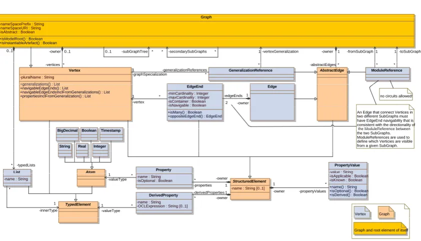
Figure 2. The structural overview of the modelling elements available in Gmodel
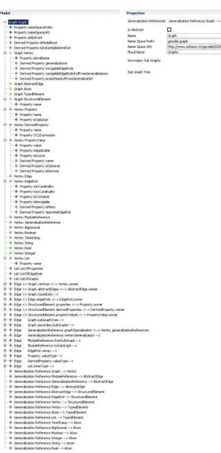
Figures 3 and 4 show how Gmodel has been encoded in itself to achieve a first imple-mentation.
4. Instantiation semantics
4.1. Features for modelling of graphs.
Graph: A graph consists of a collection of vertices and a collection of edges. In
Gmodel the links between a graph and the vertices and edges constituting the graph are encoded as physical containment - a graph artefact contains or in-cludes vertices and edges, and no vertex or edge can exist independently from a containing graph.
This concept is equivalent to the containment concept in the UML, which also demands lifetime-dependency between container and contained parts. Since the term container or containment heavily used in many contexts in software engi-neering, Gmodel uses the term owner to refer to containment in the strict sense involving lifetime-dependency as described above. Each element in Gmodel must have exactly one active owner at a given point in time. The graph artefact that encodes Gmodel is a special case (and the only such case) where the owner of a a graph is the graph itself.
Vertex: A vertex is the source and the target of any number of edges.
Figure 4. Encoding of edges
Edge end: An edge end is connected to a vertex and determines whether the
vertex is visible from the vertex connected to the edge end at the other side of the edge.
Sub graph tree: The content of a graph (vertices and edges) can be organized
Secondary sub graphs: The sub graph tree may also contain sub graphs that (independently from containing sub sub graphs) reference further sub graphs. Thus secondary sub graphs provide the mechanism needed to represent overlap-ping sets of sub graphs.
4.2. Fundamental features for meta modeling.
4.2.1. Generalizations.
Generalization: A graph may refer to one or more generalizations. All
general-izations of a graph are graphs as well. A specialization inherits all properties from its generalizations. However inheritance of properties does not imply poly-morphism in the object oriented sense.
A specialization may not redefine any inherited properties, and although a graph may have multiple generalizations, any property definitions inherited from more than one generalization must be traceable back to exactly one common root in the generalization hierarchy.
Is abstract: A graph has a property to indicate whether it can be instantiated
or whether it only serves as an abstract generalization that has instantiable specializations.
Abstract edge: An abstract edge is an abstract generalization of an edge.
4.2.2. Element.
Element: All vertices (or graphs) in the encoding of Gmodel are either direct or
indirect specializations of Element. Each element is an instance of a metatype, which provides the basis for distinguishing meta levels. In Gmodel there is no artificial limits to the number of meta levels. Hence any concrete (non-abstract) graph can be used in the role of a meta model, and Gmodel can be used to create ”instantiate” a graph (a meta model).
Structured element: In Gmodel there is a conscious distinction between
struc-tured elements that may have properties (vertex, abstract edge, and edge end) and the other elements that may not have properties. Structured elements consti-tute first-class meta modelling concepts whose properties are used as a template that determines which property values are available when a vertex (or Graph) is instantiated.
Typed element: Vertices, atoms, and lists may be used as inner types in lists,
and are therefore encoded as specializations of a common generalization called typed element.
Property: Properties are part of the definition of a structured element. A property
Property value: The metatype of a property value is always a property. Property values constitute the items that can be set in Gmodel after a structured element has been instantiated. If a property has been defined as optional, then this means that there may be some instances of a structured element where the property is not applicable and hence the associated property value is set to the state of not-applicable. When setting a property value Gmodel only accepts the state of not-applicable if the property is defined as optional. The other two states of a property value (unknown and known) are permissible both for optional and mandatory properties.
4.2.3. Atom.
Atom: Every property refers to exactly one value type. All permissible value types
are atomic in the sense of not containing substructures that are accessible in the form of properties. Atoms constitute the insulation layer between the problem space (which is modelled) and an underlying solution space (the platform or implementation technology that is being abstracted away by models). Gmodel comes with an extensible predefined set of atoms. Users are able to plug in addi-tional (domain specific) atoms as required. Property values are always instances of atoms. Instances of atoms are serializable and are they are persisted as part of a graph in all the places where they are referred to by a property value (via the metatype of the property value and the value type of the metatype).
4.2.4. Edge end.
Minimum cardinality: The minimum cardinality of the associated vertex. This
property is only relevant when the graph is used in the role of a meta model.
Maximum cardinality: The maximum cardinality of the associated vertex. This
property is only relevant when the graph is used in the role of a meta model.
Is container: Only one of the two edge ends associated with an edge can act in
the role of container. If an edge is used to model containment, then there needs to be navigability from the container to the contained part. This property is only relevant when the graph is used in the role of a meta model.
Is navigable: Is used to indicate in which way the associated edge can be
nav-igated. This property is only relevant when the graph is used in the role of a meta model.
4.3. Features to support modularity.
4.3.1. Graphs.
Graphs are specialized vertices: When a graph owns a large number of vertices
allows a hierarchical drill-down perspective into set of sub graphs. In Gmodel this is achieved by encoding a graph as a specialization of a vertex, such that an element that appears as a vertex in a graph, may at the same time be expanded into a sub graph that contains further vertices and edges.
This approach avoids the need to introduce an additional - in many ways artificial - concept for modularity. Graphs in the role of specialized vertices together with the sub graph tree constitute the foundation for modularity in Gmodel. In practice the role of some graphs is exclusively one of sub graph owner and architecture owner for these sub graphs.
Instantiable artefacts: Non-abstract graphs are the only elements in Gmodel
that can be instantiated as independent physical artefacts. This means that Gmodel does not allow the creation of any non-graph elements outside the con-text of a graph (in the role of owner). Gmodel starts treating a non-abstract graph as an independent physical artefact as soon as the graph is referenced via a sub graph tree link from another graph. A graph may only be removed from the sub graph tree when it no longer contains any vertices (and by implication any edges). Gmodel discontinues treating a graph as an independent physical artefact as soon as it is no longer referenced from any graph in the sub graph tree.
Lastly vertices and edges are only allowed to be added to a graph that is not referenced in a sub graph tree if the graph itself constitutes the top element in the sub graph tree. Taken together this constitutes a policy that imposes modularity at exactly one level of granularity (the graph) by guaranteeing that all non-empty graphs are independent physical artefacts.
This policy differs noticeably from the two prevailing policies applied by software modelling tools, namely the policy of making modularity an optional aspect that the modeller may chose to ignore (which is commonly used applied by tools that don’t shield the user from file system level abstractions), and the policy of enforcing modularity at the level of atomic model elements (which is commonly applied in repository based tools that abstract away the file system).
4.3.2. Dependency management between graphs.
Secondary sub graphs: Only very few graphs encountered in practice in
soft-ware engineering can be fully represented in a sub graph tree containing non-overlapping sub graphs. This leads to the concept or secondary sub graphs which allow the representation of overlapping sets of sub graphs. This feature is essential for actively managing the complexity in any non-trivial model.
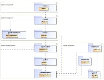
Figure 5. Example of a modular graph consisting of several sub graphs
allowable from an architectural perspective. Note that the sub graph tree ref-erence between a graph and its contained sub graphs points to vertices (sub graphs) that are also owned by the graph (via the owner vertices link between graph and vertex).
Repositories: Gmodel abstracts away file system level abstractions as far as
pos-sible. Instead of files, the user interacts with Gmodel via a repository concept. The Gmodel repository concept builds on the sub graph tree feature. Every graph in a sub graph tree may be nominated as a repository, in which case the graph in question holds a reference to a server and a folder in a file system.
The graphs that are physically stored in a repository are all the graphs in the sub graph tree of the repository with the exception of those that are reposito-ries themselves and their respective sub graph trees. This means that Gmodel repositories may be geographically distributed as required to provide optimal performance for users working (primarily) on specific models in a specific lo-cation. Within a Gmodel repository each graph is stored as a file in a folder structure that mirrors the sub graph tree.
Figure 6. Example of unidirectional edges across two sub graphs
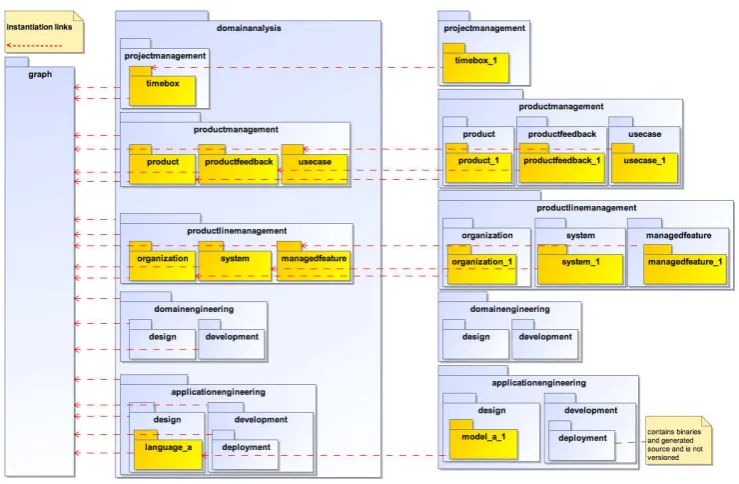
Figure 7. Instantiation links between graph, DSL definitions, and DSL models
[image:15.595.130.500.344.586.2]Product repositories: A product repository is a repository that stores internally consistent sets of versions and variants of graph artefacts, that is such a set of artefacts constitutes the source specification of a deployable product release.
Project repositories: A repository that stores versions and variants of the work
of a project team. The content of a project repository is always an extract from a product repository. While a user is modifying a graph artefact, he or she has an exclusive lock on the artefact. A [graph] artefact may be part of multiple projects, but may only be modified in one project at a time.
Once an artefact has been modified as part of a project, any second or fur-ther project requesting to modify the artefact is provided with the latest version (across all project repositories) of the artefact. This approach encourages fre-quent integration of results between projects that, and it discourages the common practice of modifying artefacts in any number of projects, and worrying about integration later.
At the level of traditional code based specification (as opposed to model based specifications) such a restrictive approach would be unrealistic due to the poor separation of concerns in such specifications. Highly modular model based speci-fications however allow for a very good separation of concerns, and hence min-imise the need for several modellers to work on the same artefact at the same time. If variants of an artefact are consistently expressed via explicit language elements for delta-modelling, then all copy and paste practices become obsolete, and there is no longer any need for sophisticated diff and merge tooling.
Module references: Achieving good overall modularity in the sense of loose
cou-pling between modules requires not only features that allow modules to be cre-ated, but also features that enable architects to articulate allowable dependencies between modules.
In Gmodel the owner of a graph is also known as the architecture owner. This terminology reflects the architectural significance of the owner for all the sub graphs it contains. A graph in the role of architecture owner contains one or more module references between sub graphs that are either part of the architec-ture owner’s sub graph tree or its collection of secondary sub graphs. Module references indicate constraints for the dependencies that may exist between the sub graphs owned by or referenced by the architecture owner.
A dependency between two sub graphs amounts to an edge between a vertex owned by one of the sub graphs and a vertex owned by the other sub graph. As described earlier, such cross-graph edges are only navigable in one direction, and the module references defined in the architecture owner (a) determine whether such a cross-graph edge is allowed at all, and (b) indicate the allowable naviga-bility (and by implication visinaviga-bility) of edges between the sub graphs in question.
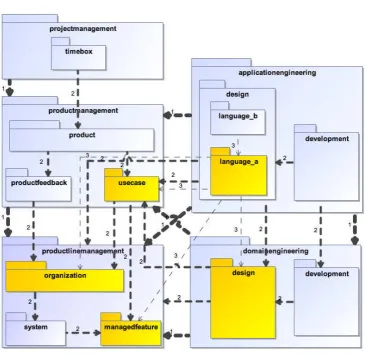
Figure 8. Example of module references at different levels in a sub graph hierarchy
Overall the rules around Gmodel repositories and module references are intended to provide fractal scalability: modelling is only possible in an architectural con-text, and any graph plays the role of architecture owner for its sub graphs. In order to ensure that architecture definitions can never get out of sync with the graphs they apply to, module references can only be removed once there are no remaining cross-graph edges between the corresponding sub graphs.
4.3.3. Extensibility.
Specializations of the Gmodel graph: Gmodel is intended to be extensible.
When Gmodel is used to instantiate a graph that is linked to the Graph element in Gmodel via a generalization reference, then this graph is treated as an exten-sion of Gmodel. That is, the graph is treated at residing on the same meta level as Gmodel. Such an extension of Gmodel may then include further vertices and edges beyond what is provided in Gmodel, as well as specializations of vertices, abstract edges, typed elements, and structured elements.
One usage scenario for such extensions is the scenario where a meta language is needed that can can act in a pivot role for interoperability between multiple meta languages. Other usage scenarios include specialized functionality for manipulat-ing graphs in specific domains or integration with specific version management software.
An important difference between inheritance in object orientation and gener-alization/specialization hierarchies in Gmodel is that edges are not treated as properties. When specializing a graph, by default only properties are inherited and become visible in the specialization, and not edges. However, a
generaliza-tion reference may optionally be defined with inherited edge visibility enabled,
which enables edges defined in a generalization be be instantiated as part of an instance of the specialization.
One example scenario where inherited edge visibility enabled is needed, is the scenario of extending (specializing) Gmodel with further modelling elements. A similar scenario exists when extending a language defined in Gmodel with further elements.
A scenario whereinherited edge visibility enabled is explicitly not desired is the scenario of the scenario of extending (specializing) Gmodel such that only spe-cializations of Gmodel elements are instantiable by users of the language. A concrete example would be the definition of an entity relation modelling lan-guage in Gmodel, where a Schema is defined as the model root, and Entities, Attributes, and Relationships are the only elements that should be instantiable within a Schema (and not Vertices, Edges, etc. - even if Schema is defined as a specialization of Graph).
5.0.4. Terminology.
Artefact: the unit of persistent storage used in GraphRepositories
ArchitectureOwner: The ArchitectureOwner of a Graph is the parent of the
Graph in the subGraphTree
CurrentModelRoot: The CurrentModelRoot is the ModelRoot that is part of
the state of an in memory instance of Gmodel and it reflects the artefact that the user is currently working with
GraphRepository: a facility for persistent storage of Graph artefacts that
en-forces all semantics associated with subGraphTrees, secondarySubGraphs, and ModuleReferences in Gmodel
ModelRoot: A ModelRoot is a Graph that has the role of an Artefact. (Not all
Graphs are a ModelRoot but all ModelRoots are Graphs)
ProductRepository: A GraphRepository that stores Versions and Variants of
deployable Products
ProjectRepository: A GraphRepository that stores Versions and Variants of the
work of a ProjectTeam. The content of a ProjectRepository is always an extract from a ProductRepository
Visibility: The Visibility from the CurrentModelRoot includes all those Elements
5.1. instantiate Gmodel as a Graph in Graph.gmodel.
Purpose: definition and validation of the InstantiationSemantics (encoding) for
Graphs
Pre conditions: the LanguageDesigner has expressed a draft of Gmodel in Ecore
and has written this use case
Post conditions: The metatype of any Graph is a Graph with the name of ”Graph”
encoded in a PropertyValue, and there is a ”Graph.gmodel” artefact that con-tains the Graph ”Graph”
Frequency of use per day per system: 1.0E-4
Actor Step
ProductArchitect 1. implements the ”owner vertices” references be-tween the classes Graph and Vertex with con-tainment semantics (lifetime dependency) ProductArchitect 2. implements functionality to instantiate a Graph
and its properties and propertyValues
ProductArchitect 3. requests Gmodel to instantiate a new Graph where the propertyValue called name is set to ”Graph”
Gmodel 4. instantiates a Graph (in memory) where the propertyValue name is ”Graph” and where the propertyValues pluralName, nameSpaceURI, nameSpacePrefix, and isAbstract are set to the values requested by the ProductArchitect (as defined in the Ecore draft of Gmodel)
ProductArchitect 5. requests Gmodel to instantiate further Graphs that are vertices owned by the ModelRoot ”Graph” (Vertex, AbstractEdge, Atom, Type, StructuredElement, and Element - as defined in the Ecore draft of Gmodel, with all the proper-tyValues as defined in the Ecore draft)
Gmodel 6. instantiates further Graphs that are owned by ”Graph” as requested by the ProductArchitect that have propertyValues set to the values re-quested by the ProductArchitect
ProductArchitect 7. requests Gmodel to instantiate Vertices that are owned by the ModelRoot ”Graph” (List, BigDecimal, Boolean, Timestamp, String, Real, Integer, Property, EdgeEnd, Edge, Generaliza-tion, PropertyValue, and ModuleReference - as defined in the Ecore draft of Gmodel, with all the propertyValues as defined in the Ecore draft) Gmodel 8. instantiates Vertices that are owned by ”Graph” as requested by the ProductArchitect that have propertyValues set to the values requested by the ProductArchitect
9. execute use case store Graph [store the Graph named ”Graph”]
ProductArchitect 10. implements the full functionality of two of the specializations of AbstractEdge (Edge and Gen-eralization)
Actor Step
ProductArchitect 12. requests Gmodel to instantiate all the Abstract-Edges (Abstract-Edges and Generalizations) that are shown in the Ecore draft of Gmodel
Gmodel 13. instantiates Edges and Generalizations that are owned by ”Graph” as requested by the Pro-ductArchitect
14. execute use case store Graph [store the Graph named ”Graph”]
15. execute use case define Atoms as external Arte-facts in Graph.gmodel
16. execute use case create a ModuleReference with Gmodel
5.2. define Abstract Syntax.
Purpose: definition of abstract syntax of a domain specific language
Pre conditions: the Gmodel editor is open and a ProjectRepository has been
selected
Post conditions: a Graph that contains a meta model has been stored
Frequency of use per day per system: 0.1
Main Flow:
Actor Step
Gmodel Editor 1. displays the SubGraph tree of the ProjectRepos-itory
LanguageDesigner 2. requests the creation of a meta model at the appropriate location in the SubGraph tree Gmodel Editor 3. creates a Graph with the name supplied by the
LanguageDesigner
Gmodel Editor 4. obtains an exlusive lock on the new Graph for the LanguageDesigner
Gmodel Editor 5. displays the modeling perspective for for the new Graph
LanguageDesigner 6. defines the Elements of the domain specific lan-guage
LanguageDesigner 6. links the new Elements as required to existing Elements that are within visibility
Gmodel Editor 7. commits the Graph to the ProjectRepository 8. execute use case define Abstract Syntax
Alternate flow: 8a
Condition: LanguageDesigner choses to exit Gmodel editor
Actor Step
Gmodel Editor 1. closes editor window
2. End of use case
Exception: 3a
Condition: name of the Graph is not unique within name space
Frequency of use per day per system: 0.02
Message: name of the Graph must be unique within name space
Actor Step
1. Continue with: define Abstract Syntax [Step 2.]
5.3. create a ModuleReference with Gmodel.
Purpose: enable Gmodel to enforce ModuleReference constraints defined in the
ArchitectureOwner of a Graph
Pre conditions: the use case ”define Atoms as external Artefacts in Gmodel” has
been executed
Post conditions: the ModuleReference ”SGA-¿SGB” has been stored in the
Ar-chitectureOwner of SGA
Frequency of use per day per system: 1.0
Actor Step
ProductArchitect 1. implements the full functionality of the Mod-uleReference specialization of AbstractEdge 2. execute use case load GraphRepository [load a
GraphRepository]
3. execute use case model a Graph [model a Graph ”GTest”]
4. execute use case model a Graph [model a Graph ”SGA” as a subGraph of ”GTest” such that it has a Vertex ”SGAV1”]
5. execute use case model a Graph [model a Graph ”SGB” as a subGraph of ”Gtest” such that it has a Vertex ”SGV1”]
6. execute use case model a Graph [model the Graph ”GTest” to instantiate a ModuleRefer-ence ”SGA-¿SGB”]
7. execute use case store Graph [store Graphs ”GTest”, ”SGA”, and ”SGB”]
8. execute use case model a Graph [model the Graph ”SGA” such that an Edge from ”SGAV1” to ”SGBV1” is instantiated]
9. execute use case store Graph [store Graph ”SGA”]
Exception: 4a
Condition: ”SGA” is already a subGraph of ”GTest’
Frequency of use per day per system: 0.01
Message: Graph [name] is already a subGraph of [name]
Actor Step
1. End of use case
Exception: 5a
Condition: ”SGB” is already a subGraph of ”GTest’
Frequency of use per day per system: 0.01
Message: Graph [name] is already a subGraph of [name]
Actor Step
1. End of use case
Alternate flow: 6a
Condition: the GmodelUser forgets to define a ModuleReference ”SGA-¿SGB” in
”GTest”
Actor Step
1. Continue with: create a ModuleReference with Gmodel [Step 8.]
Exception: 6b
Condition: the ”SGA-¿SGB” ModuleReference already exists in ”GTest”
Frequency of use per day per system: 0.01
Message: The ModuleReference [name] is already defined
Actor Step
1. Continue with: create a ModuleReference with Gmodel [Step 8.]
Exception: 8a
Condition: no ModuleReference ”SGA-¿SGB” is defined in ”GTest”
Frequency of use per day per system: 0.01
Message: An Edge between [Vertex1. name] and [Vertex2.name] can’t be
instan-tiated as it violates the architecture defined in [ArchitectureOwner of Vertex1]
Actor Step
1. End of use case
5.4. define Atoms as external Artefacts in Graph.gmodel.
Purpose: enabling LanguageDesigners to extend Gmodel with further Atoms as
required
Pre conditions: a first working implementation of Gmodel is available
Post conditions: the ”Graph” Graph that represents Gmodel refers to
exter-nal Atom Artefacts ”BigDecimal.atom”, ”Boolean.atom”, ”Timestamp.atom”, ”String.atom”, ”Real.atom”, ”Integer.atom”
Frequency of use per day per system: 0.0010
Actor Step
ProductArchitect 1. implements the functionality to delete Elements from ”Graph”, and functionality to instantiate Atoms as independent external ”.atom” arte-facts outside of a Graph
ProductArchitect 2. requests Gmodel to store the following Ver-tices (BigDecimal, Boolean, Timestamp, String, Real, Integer) as ”.atom” artefacts in a GraphRepository located at [location name] Gmodel 3. creates ”.atom” files for BigDecimal, Boolean,
Timestamp, String, Real, and Integer (but does not keep any representation in memory) in the GraphRepository [location name]
ProductArchitect 4. modifies the Graph.gmodel artefact in a text editor such that all Properties reference the ”.atom” artefacts rather than the Atoms defined within Graph.gmodel
5. execute use case load GraphRepository [load the GraphRepository containing Graph.gmodel]
ProductArchitect 6. requests Gmodel to delete the following Ver-tices (BigDecimal, Boolean, Timestamp, String, Real, Integer) from the ”Graph” Graph
Gmodel 7. deletes the requested Vertices from ”Graph” 8. execute use case store Graph [store ”Graph” in
Graph.gmodel]
5.5. explore subGraphTree.
Purpose: expansion of the subGraphTree
Pre conditions: a GraphRepository has been loaded and this use case may have
been executed zero or more times
Post conditions: the LanguageDesigner has navigated to a selected ModelRoot
one level down in the subGraphTree
Frequency of use per day per system: 1000.0
Actor Step
Gmodel 1. returns the list of subGraphs of the Current-ModelRoot for which the GmodelUser has at least one of the CRUDX rights
Gmodel User 2. requests to expand one of the subGraphs re-turned by Gmodel
Gmodel 3. sets the CurrentModelRoot to the selected sub-Graph
4. execute use caseexplore subGraphTree
Alternate flow: 2a
Condition: the user requests to [Read—Update—Delete—Execute] one of the
sub-Graphs returned by Gmodel and has appropriate Permissions
Frequency of use per day per system: 1000.0
Actor Step
Gmodel 1. sets the CurrentModelRoot to the selected sub-Graph
Gmodel 2. performs the requested action
3. Continue with: explore subGraphTree [Step 4.]
Exception: 2b
Condition: the Gmodel User requests to [Read—Update—Delete—Execute] one
of the subGraphs returned by Gmodel and does not have appropriate Permissions
Frequency of use per day per system: 100.0
Message: Lacking permision for the [Read—Update—Delete—Execute] action on
[CurrentModelRoot]
Actor Step
1. Continue with: explore subGraphTree [Step 1.]
5.6. instantiate a ModelRoot.
Purpose: creating a new ModelRoot and adding it to the subGraphTree
Pre conditions: a GraphRepository has been loaded
Post conditions: a new ModelRoot is attached to the in memory subGraphTree
and is the CurrentModelRoot
Frequency of use per day per system: 50.0
Actor Step
Gmodel User 1. requests Gmodel to instantiate a ModelRoot of metatype [metatype name]
Gmodel 2. instantiates a ModelRoot with [name] (supplied by the GmodelUser) of metatype [metatype name]
Gmodel 3. attaches the new ModelRoot as an element of the subGraphTree at the CurrentModelRoot Gmodel 4. makes the newly instantiated ModelRoot the
CurrentModelRoot
5.7. load GraphRepository.
Purpose: instantiating an in memory representation of the content of a
GraphRepos-itory
Pre conditions: an artefact named ”Graph.gmodel” and an artefact named
[lo-cation name].gmodel exist in the lo[lo-cation [lo[lo-cation name]
Post conditions: Gmodel has the subGraphTree (and optionally all Graphs)
con-tained in the GraphRepository at [location name] in memory
Frequency of use per day per system: 50.0
Main Flow:
Actor Step
Gmodel User 1. requests Gmodel to load the GraphRepository at [location name] into memory
Gmodel 2. loads Graph.gmodel and [location name].gmodel into memory
Gmodel 3. traverses the structure that corresponds to the subGraphTree hierarchy of [location name].gmodel to load all Graphs contained in the GraphRepository into memory
Alternate flow: 2a
Condition: the metatype of the ModelRoot of [location name].gmodel is not Graph
but a specialization (direct or indirect via a series of generalization/specialization Edges) of Graph
Actor Step
Gmodel 1. loads Graph.gmodel and [location name].gmodel into memory
Gmodel 2. traverses the generalization/specialization Edges between the metatype of the ModelRoot of [location name].gmodel and Graph.gmodel and loads all the meta meta models encountered in this traversal into memory
3. Continue with: load GraphRepository [Step 3.]
Alternate flow: 3a
Condition: the LanguageDesigner chose the option to only load the subGraphTree
Frequency of use per day per system: 5.0
Actor Step
Gmodel 1. traverses the structure that corresponds to the subGraph hierarchy of [location name].gmodel to load the subGraphTree structure of the GraphRepository into memory
2. End of use case
5.8. model a Graph.
Purpose: definition of the Elements of a Graph
Pre conditions: some GmodelEditor has loaded a GraphRepository
Post conditions: a Graph that contains Elements has been instantiated in
mem-ory
Frequency of use per day per system: 1000.0
Main Flow:
Actor Step
Gmodel User 1. requests Elements to be added to the Current-ModelRoot
Gmodel 2. adds the new Elements to the CurrentModel-Root or one of the Elements contained in the CurrentModelRoot
Alternate flow: 1a
Condition: the Graph that the GmodelUser wants to model does not yet exist in
the loaded GraphRepositoryTree
Actor Step
Gmodel User 1. requests the instantiation of a new ModelRoot [name] at the CurrentModelRoot
2. execute use caseinstantiate a ModelRoot
3. Continue with: model a Graph [Step 1.]
Alternate flow: 1b
Condition: the Graph that the GmodelUser wants to edit is not part of the
first-level Elements in the SubGraphTree of the CurrentModelRoot
Frequency of use per day per system: 500.0
Actor Step
1. execute use case explore subGraphTree [explore SubGraphTree to change the CurrentModelRoot to the approriate location]
2. Continue with: model a Graph [Step 1.]
5.9. store Graph.
Purpose: persistent storage of a Graph
Pre conditions: Gmodel has a Graph with name [name] in memory and this
Graph is a ModelRoot
Post conditions: the [name] Graph has been stored (persisted) in the artefact
[name].gmodel, and the [name] Graph remains in memory
Frequency of use per day per system: 1000.0
Main Flow:
Actor Step
Gmodel User 1. requests Gmodel to store (persist) the in mem-ory Graph with name [name] using the artefact name ”[name].gmodel”
Gmodel 2. stores (persists) the in memory Graph with name [name] using the artefact name ”[name].gmodel” in the GraphRepository structure that corresponds to the subGraph hierarchy of the [name] Graph
5.10. instantiate a Graph.
Purpose: extended validation of the InstantiationSemantics (encoding) for Graphs
(beyond the instantiaton of Gmodel in itself)
Pre conditions: the LanguageDesigner has expressed a draft of an E/R modellig
Post conditions: A Product-Order-Customer model has been instantiated in the Schema E/R modelling language, which has been defined in Gmodel
Frequency of use per day per system: 1.0
Main Flow:
Actor Step
1. execute use casemodel a Graph [model a graph called Schema, with vertices Entity and At-tribute, and with edges Relationships (between two Entities) and Attributes (between Entity and Attribute with containment semantics)]
LanguageDesigner 2. requests Gmodel to instantiate the Schema graph
Gmodel 3. instantiates the Schema graph (in memory)
[Rule A]
LanguageDesigner 4. specifies propertyValues for the Schema
LanguageDesigner 5. requests the addition of the Product entity to the Schema
Gmodel 6. The Product entity is instantiated [Rule B] LanguageDesigner 7. requests the addition of the Order entity to the
Schema
Gmodel 8. The Order entity is instantiated [Rule B] LanguageDesigner 9. requests the addition of the Customer entity to
the Schema
Gmodel 10. The Customer entity is instantiated [Rule B] LanguageDesigner 11. specifies propertyValues for the instantiated
Actor Step
LanguageDesigner 12. requests the addition of a Relationship from Or-der to Customer
Gmodel 13. Instantiate all properties of the edge Relation-ships as propertyValues of the RelationRelation-ships instance that have a name corresponding to the name of the instantiated property and a metatype that points to the valueType of the instantiated property
Gmodel 14. Instantiate all properties of the edge ends at Or-der and Customer as propertyValues of the Rela-tionships instance that have a name correspond-ing to the name of the instantiated property and a metatype that points to the valueType of the instantiated property.
LanguageDesigner 15. specifies propertyValues for the instantiated re-lationship and associated edge ends
LanguageDesigner 16. requests the addition of a Relationship from Or-der to Product
Gmodel 17. Instantiate all properties of the edge Relation-ships as propertyValues of the RelationRelation-ships instance that have a name corresponding to the name of the instantiated property and a metatype that points to the valueType of the instantiated property
Gmodel 18. Instantiate all properties at the edge ends of Or-der and Product as propertyValues of the Rela-tionships instance that have a name correspond-ing to the name of the instantiated property and a metatype that points to the valueType of the instantiated property
LanguageDesigner 19. specifies propertyValues for the instantiated re-lationship and associated edge ends
LanguageDesigner 20. decorates the instantiated Schema and other el-ements (Entities, Attributes, Relationships etc.) with the properties relevant for instantiation at the next level down
Alternate flow: 2a
Condition: the LanguageDesigner has specified a GeneralizationReference from
Schema to Graph
Actor Step
1. The use case continues with rule C being appli-cable [Rule C]
2. Continue with: instantiate a Graph [Step 2.]
Rules
A: Any properties of the graph Schema are instantiated as propertyValues of the Schema instance that have a name corresponding to the name of the instanti-ated property and a metatype that points to the valueType of the instantiinstanti-ated property.
B: Any properties of Entity are instantiated as propertyValues for the instantiated entity. Each propertyValue has a name corresponding to the name of the instan-tiated property and a metatype that points to the valueType of the instaninstan-tiated property.
Use Case Design
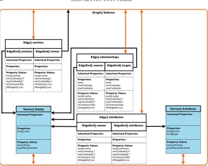
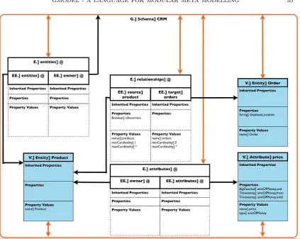
Figures 9 to 11 illustrate the E/R modelling language, and show the intended use of the Gmodel property and property value concepts. The notation used is a possible (heavily graphical) concrete syntax for Gmodel based models:
• The diagrams correspond to the main flow of theinstantiate Graph use case.
• All rectangular boxes in the diagrams represent objects in an implementation language such as Java.
• All arrows can be read as references between objects in an implementation lan-guage.
• Bidirectional arrows represent pairs of opposite references.
• Colour coding is aligned with the Gmodel overview picture: blue for vertices, and organge for graphs. Egdes and edge ends are without colour. Orange ar-rows repesent theowner-verticesandowner-abstactEdges links from the Gmodel overview picture at the level of instances.
• name1] name2 means that name1 is the metatype ofname2. The@ symbol has
been used to indicate objects that don’t have a name.
• Properties of edges are not shown in the diagrams, as the example only requires properties of edge ends. Additionally the implementation of the links between edges and edge ends has been abstracted away to keep the diagrams readable.
6. comparison with other approaches
ToDo ◮summary of the shortcomings of existing tooling◭
6.1. Outlook. In a further paper we will outline the work in progress on building