Schematic Design Tools
Schematic Design Tools
stored in a retrieval system, or transmitted, in any form or by any means, electronic, mechanical, photocopying, recording, or otherwise without the prior written consent of OrCAD L.P.
Every precaution has been taken in the preparation of this publication. OrCAD assumes no responsibility for errors or omissions. Neither is any liability assumed for damages resulting from the use of the information contained herein.
OrCAD® is registered trademark of OrCAD L.P.
IBM® is a registered trademark of International Business Machines Corporation. PAL® is a registered trademark of Advanced Micro Devices Inc.
DM/PL ™ is a trademark of Houston Instruments.
HP-GL® is a registered trademark of Hewlett-Packard Company. VersaCad® is a registered trademark of VersaCad Corporation. Postscript® is a registered trademark of Adobe Systems Incorporated.
All other brand and product names mentioned herein are used for identification purposes only, and are trademarks or registered trademarks of their respective holders.
McBoole is a public domain process developed by Michel Dagenais of McGill University.
Document Number: OR9062B 3-31-91
3175 NW Aloclek Drive Hillsboro, Oregon 97124-7135
U.S.A. Sales & Administration Technical Support
24-Hour Bulletin Board System
FAX
Chapter 1: Welcome to OrCAD Schematic Design Tools... 1
Finding the information you need ... 1
Installation ... ... 1
Project-oriented design environment... 2
Learning Schematic Design Tools... 2
Beyond the basics... 2
What's new in the design environment?... 3
Tools... 4
Editors... 5
Processors... 5
Librarians... 7
Reporters.. .. .. .. .. .. .. .. .. .. .. .. .. .. .. . .. .... .. .. . . .. .. .. .. .. .. .. .. .. ... ... . ... .... ... .. .. .. .. .... . .. .. .. 8
Transfers... 9
Graphic objects... 10
Parts ... 10
Wires ... 10
Buses ... 11
Junctions ... 11
Power objects.... ... ... ... ... 11
Module ports ... 11
Sheet symbols... 11
Labels ... 12
Text ... 12
Title block... ... 12
Stimuli ... 12
Test vectors... 12
Trace ... 12
Layout directives... ... .... ... ... ... 12
The design process... 13
Design structures... .. .. .. .. .. .. .. .. .. .. . .. . . .. .. .. .. .. .. .. .. .. .. .. .. .. .. .. . ... ... .. ... .. .. .. . ... .. .. . .. .. 14
Flat designs... 14
Hierarchical designs ... 17
Chapter 2: Introducing Draft ... 23
Before you begin... 23
Keys ... 23
Keyboard input ... 24
Operating system command prompt... ... ... ... ... ... ... .... 24
Filenames... 25
Designs ... 25
Running ESP.. .... ... .... ... ... ... ... ... ... ... ... .... ... .... ... ... .... ... ... ... .... ... ... ... ... 26
Changing to the TUTOR design... 27
Change the start up design... 28
Running Schematic Design Tools... 29
Defining title block information ... 30
View Schematic Design Tools' configuration... 30
Running Draft... 32
DrCAD basics ... 33
Mouse basics... 33
Display the main menu... 33
CoIllll'lalld.s . . . . .. .. .. .. .. .. .. .. .. .. .. .. .. . .. .. .. .. .. .. .. .. .. .. .. .. .. .. .. . .. . .. . .. . . .. . .. .. . . .. .. . . 34
How command names are shown in this guide ... 35
Return to the main menu... 35
Setting up Draft's work conditions ... 36
Display work conditions settings... 36
Auto Pan ... 36
X, Y Display... 37
Worksheet size ... 38
Changing your view of the worksheet... 39
Zoom in and out ... 39
Grid parameters... 40
Updating the worksheet ... 41
Update the file ... 41
Creating a macro ... 42
Save the macro ... 43
Exi ting Draft... 44
Setting up automatically... 45
View the configuration ... 45
Chapter 3: Capturing the clock oscillator schematic... 47
RuhningDraft ... , ... ' ... ; ... 47
About symools ... ; ... O"O... 48
Abou t libraries... 48
Where to start... 48
Check library files ... ;... 49
Placing parts ... ; .... ','" ~""", ... ;... ... .. .. .... ... ... 51
Shortcuts for getting patts ... .. .. .. .. ... .. .. ... 52
Place the remaining parts ... 52
Placing wires ... ;... 53
Place wires... 53
Placing junctions at interSections ... 54
Place junctic:>ns... 54
Editing ..
part
fields ...55
Edit part fields.~.;... 56
Edit part fields for the remaining parts ... : ... 58
Specifying connections ... :... ... 59
Add a laQel ... ~ ... 59
Placin~ cOmII\ent text ... ;... .. .. .. .. .. .. .. . .. 60
Add a title... 60
Updating the file ... ~ ... ; ... 60
Summary ... 60
Chapter 4: Capturing the power regulator schematic ... 61
Continuing schematic captUre.; ... 62
Moving a group of objects ... ~... 62
Move the clock osdllatorcircuit to another place on the worksheet ... 62
Building the power. regulator circuit... 63
Get library parts ... ;.~ ... ~... 63
Oele~ing parts fr~m the worksheet... 64
Delete an object .... ~ ... ;. .. .... ... .... .. .... .. . .. .. .. .. .. .. .. .... .. .. .. .. .. . .. 64
Recover a. deleted objeCt ... ; ... ;... 64
Rota. ting parts .... ; ... :... 65
Placing wires ... ; .. ;... 66
More macros... 67
Write a macro to ... 67
Save the macros... 68
Placing power symbol... 68
Dragging wires... 69
Editing part fields ... ~... 70
Edit part values for the capacitors and battery ... ~... 70
Placing comment text... 70
Add a title... 70
Changing viewpoints... 71
Jump to new coordinates... 71
Tag and jump to specific locations... 72
Making a draft-quality print... 73
Update the file... 73
Make a hardcopy of the worksheet ... 73
Ending a Draft work session ... 74
Summary ... 74
Chapter 5: Creating a custom component... 75
Running Edit Library... 75
Configure Edit Library ... 76
Run Edit Library ... 76
Setting up the work conditions. ~... 76
Make part body border and grid dots visible... 76
Beginning a new part ... ~... 77
Open a part editing pad... 77
Drawing the body outline ... 79
Changing the reference designator... 80
Change reference designator prefix to 'D' ... 80
Creating a part body... 81
Zoom in to gain finer pointer control. ... 81
Draw a rectangle to represent an LED ... 82
Draw six more segments ... ~... ... ... 82
Add the decimal point... 83
Adding pins to a part... 85
Add a clock pin... 85
Add a reset pin ... 85
Add the remaining pins... 86
Saving a new part ... 87
Save the new part... 87
Write the library in memory to a file on disk ... 88
Get the new part... 88
Summary ... 88
Chapter 6: Capturing the logic and display circuit schematic... 89
Choosing components... 89
Re-running Draft... 90
Drawing a portion of the schematic... ... 91
Change viewpoint to a clear area... 91
Place the components... 92
Place the wires ... 93
Run the macro to place wires... 93
Define REPEAT parameters... 94
Change viewpoint to speed wire placement... 94
Use REPEAT to speed wire placement. ... 94
Place the remaining parts of the Minutes circuit.. ... 95
Copying a block ... ;... 96
Save a schematic block... 96
Copy a circuit ... 96
Finish the wiring... 97
View clock logic ... 102
Finishing the clock schematic ... 104
Place the remaining schematic parts ... 104
Editing remaining text ... ~ ... ~ ... , ..•. ' ... '.' ... 108
Edit the p~rt values ... ~ ... ~ ... ~ ...
lOS
Old Part Value N~me ... ; ... ~ ....• ~ ... ~~ ... 1Q8 New Part Valu~ Name ... ; ... , ... 108Add labels to the wire~ ... ~: ...•.• ! ••••••••• , •••••••••• 109.
Set repeat text piu'ameters ... = ... : ... ~ ... 1~
Placing labels wit~ repeat text ... ~ ~ ... 110
P~ac~ there~ailling re:pe~t labels ... ~ ... 110
Aq.d comme,nt text ... : ... ~ ... 1 ~ 1 Editing the title·block~ ... ~ ... : ... 112
Jump to the title, block ... 112
Eqit the title' block ... · ... · ... 112
Upq.ating'the (ile.~ .. ~ ... ~ ... ~ ... 114
Summary ... : ... 11~
Chapter 7: Using o~~er Sche~aHc Design T()Qls ... ~ ... i ... 115
Housekeepi~g ... : ... ~ ... ; ... i16
Back~p Design ... : ... ; ... :~ ... · ... ;.~ ... 116
~ename files~ ... · ... ~ ... · ... " ... oo: . . . , . . . 118
Running the Annotate Schemati~ tpol ... ~ ... 12Q Run Annotate S~hematic ()n TUTQR.sCH ... ; ... 7'
121
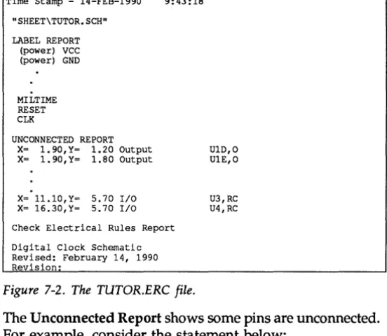
Running the ~heck' Elec~ric~l :R.ules t~qi ... " ... lZ~ View errors ... · ... ~' ... 12~Running the Create N¢tlist tool ... , ... , ... , ... 125
Generate a n~~lis.t in WIRELIST fo~a.,t .... , ... ~ ... 125
Running the Back Annotate, tQol.. ... , ... 130
Change reference de~ignator values ... 139
Running the Create BiU of Materi(ils tooL ... ~32
Make a parts list ... · ... ; ... 132
Chapter 8: Structuring your design ... 135
A simple hierarchical design ... 135
The root sheet CMOSCPU.SCH ... 137
Sheet syml>ols ... 138
Nested schematic worksheets ... 140
Design guidelines for simple hierarchies ... 143
Using Annotate Schematic on a simple hierarchy ... 144
Using the Check Electrical Rules tool on CMOSCPU.SCH ... 145
Using the Show Design Structure tool on a simple hierarchy ... 147
Using the Create Bill of Materials tool on a simple hierarchy ... 148
A complex hierarchical design ... 150
The root sheet, 4BIT.SCH ... 151
Using the Show Design Structure tool on a complex hierarchy ... 153
Converting a complex hierarchy to a simple hierarchy ... 155
A flat design ... 163
Glossary ... 165
Welcome
to
DreAD
De sign
Schematic
To
0
Is
Welcome to practical electronic engineering. You now own DreAD Schematic Design Tools, a powerful, yet
straightforward design entry tool set with the power of an engineering workstation. Using Schematic Design Tools, complex design tasks can be done in a fraction of the time it takes by hand.
Finding the
information you
need
Developed specifically to run on personal computers, Schematic Design Tools supports most popular graphics boards, printers, and plotters.
Five manuals accompany Schematic Design Tools. They are:
.:. Installation & Technical Support Guide
.:. DreAD/ESP Design Environment User's Guide .:. Stony Brook M2EDIT Text Editor User's Guide .:. Schematic Design Tools User's Guide
.:. Schematic Design Tools Reference Guide
Installation Before you begin to explore Schematic Design Tools, take a few minutes to install the tool set and register for technical support. Just follow the instructions in the
Project-oriented design environment
Learning Schematic Design Tools
Beyond the basics
Schematic Design Tools is one part of a fully integrated
Electronic Design Automation (EDA) system. The design
environment is structured to allow you to focus on whaf s important: the design. Designs are organized on a project-by-project basis, with all the design files-schematics, netlists, parts lists, simulation results, and board layouts-stored together.
The DrCAD/ESP Design Environment User's Guide
introduces the graphical environment under which Schematic Design Tools and the other OrCAD tool sets operate. In this environment, OrCAD tools and tool sets, such as Schematic Design Tools, are accessed via buttons. There are four OrCAD tool sets. They are:
.:. Schematic Design Tools .:. Digital Simulation Tools
.:. Programmable Logic Design Tools .:. PC Board Layout Tools
Buttons to access all four OrCAD tool sets display on the Design Environment screen, even if you only have one tool installed on your computer.
This User's Guide introduces Schematic Design Tools. The best way to get to know Schematic Design Tools is to start with Chapter 2: Introducing Schematic Design Tools, and proceed chapter-by-chapter through this book. You will be guided through several practice sessions that show you the basics about using Schematic Design Tools.
Once you have mastered the basics, refer to the
Schematic Design Tools Reference Guide for information
that will help you plan and create your design. The
Reference Guide explains how to tailor the configuration
What's new
in
the
design
environment?
Schematic Design Tools is one part of a fully integrated electronic design automation environment. The graphical design environment lets you:
• Run the tools within a tool set. The tools that make up Schematic Design Tools are listed in the next section.
• Move between tool sets without switching directories or copying files.
• Configure tools. Each tool can be configured and the configuration stored. This eliminates the need to enter command line switches every time a tool is used . • ) Organize designs by project. All files associated with
Tools
The tools in a tool set are organized by function: .:. Editors.:. Processors .:. Librarians .:. Reporters .:. Transfers
Figure 1-1 shows how these tools are organized on the Schematic Design Tools screen.
These functions are described briefly on the pages that follow. The explanations assume you are already familiar with common electronic design terms and concepts. If you are just learning about schema tic design, some terms we use to describe the tools may not be
familiar to you. Don't worry: basic, essential concepts and skills are thoroughly covered in chapters 2 through 7 of this guide. Advanced concepts are fully explained in the
Schematic Design Tools Reference Guide.
You can run all OrCAD tools on a single worksheet or on a multiple-sheet design. Multiple-sheet designs can be either flat designs or hierarchical designs. To learn about these different types of files, see the Design Structures
section later in this chapter.
ScJ.-.ematic: D •• i.Qn Tool. TUTOR O •• 1gn Ed! t . " . 5 Pr=V1io;or'$
Vieu ReT'vrerce
Material
L.J.br ... l ...
Edit L. •• t
L.lbr...,. L.1br..-w
Rrc;..,.1ve P.,..ts .i.ns.:;.~t.i.!I;;
ero..
C ... t . CheckR.f" ... nc:e Si 11 of' E leet.- i e . l
P' .... t . M.t .... :i..J. Rule.
COt""iVer"'t
Plot to IGES
Figure 1-1. Schematic Design Tools screen.
ESP Vx.><><
Editors
Processors
Editors are used to create or modify design files. Schematic Design Tools contains three editors:
.:. Draft. The heart of Schematic Design Tools is the schematic editor, Draft. Draft is used to create schematics, which are part of the design database .
• :. Edit File. This text editor is used to create and edit text files .
• :. View Reference Material. This tool allows you to review reference material supplied with Schematic Design Tools using a text editor. You can view files about drivers, libraries, netlist formats, and other topics of interest.
Processors are tools that subject a design file to a specific process. Schematic Design Tools includes six processors:
.:. Annotate Schematic. This tool scans schematic designs and automatically updates part reference designators (such as U?, R?). It also updates the pin numbers associated with the reference designators in multiple-parts-per-package devices. Annotate Schematic can handle very large, complex, and multiple worksheets. It can update incrementally (leaving previously
assigned reference designators alone) or unconditionally .
• :. Create N etlist. A netlist is a text file listing the logical interconnections between signals and pins. When the design becomes a real circuit board, the netlist turns into patterns of physical connections called tracks and nets. Create Netlist generates a netlist in one of over 30 different formats. Refer to
Appendix B: Netlist formats in the Schematic Design
Tools Reference Guide for a list of available formats.
You can also create your own netlist formats. See
Appendix D: Creating a custom netlist format in the
Schematic Design Tools Reference Guide for instructions.
.:. Create Hierarchical Netlist. This tool operates siPlilar to the Create Netlist tool, only it uses a hierarchical design. Hierarchical designs are discussed later in this chapter .
• :. Update Field Contents. Every library part has ten data fields used to hold text or data associated with the part. One data field holds reference designator values, such as "UIA" or "QI." Another holds the part's name, such as "74LS04" or values relevant for the part, . such as Ohm (0) values for resistors. The other eight data fields can store any information you might find useful: part tolerance, vendor name, part number, and so on. Update Field Contents changes information in a data field for parts in a schematic, based on the contents of a match file. You create tl~e
match file using Edit File's text editor .
• :. JJack Annotate. This tool updates part reference designators in your design. A list of old and new reference designators-called a Was/Is file-is used to update your schematic worksheets. You create the Was/Is file using Edit File's text editor .
• :. Cleanup Schematic. This tool checks a design for wires, buses, junctions, labels, module ports, and other opjects that are placed on top of each other .
Librarians Schematic Design Tools includes part libraries containing more than 20,000 devices. The libraries contain parts representing TIL, IEEE, CMOS, memory, ECL, discrete, analog, microprocessor, and peripheral devices.
In addition to the libraries, there are tools for managing and creating library parts. The Librarian tools are:
.:. Edit Library. This tool is a graphical editor for creating or modifying library components. With this editor, you use commands similar to Draft's to build or modify a part and add it to a library .
• :. List Library. This tool lists all the parts in a library .
• :. Archive Parts in Schematic. This tool scans a set of schematics, collects all the library parts used, and makes a library file containing only the parts used in those schematic files.
Parts can also be created or modified using a text editor, such as the one available using Edit File. If you prefer to create or modify parts in this manner, you will find the following tools very useful:
.:. Compile Library. This tool converts a text file containing library source code into a compressed library object file, the form usable by the other Schematic Design Tools .
Reporters
Plotting and printing
Reporters are tools that produce human-readable reports, but do not modify design data in any way. Reporters include:
.:. Cross Reference Parts. This tool scans the schematic files, gathers information for all parts used in the schematic files, and creates a cross reference reporting each part's location in the design .
• :. Create Bill of Materials. This tool lists all the parts used in a single schematic or in the entire design, sorted by reference designator. You can also merge additional information into the report using an
include file .
• :. Check Electrical Rules. This tool checks a design for conformity to basic electrical rules. It checks for shorts, inputs with no driving source, unconnected pins, bus contention, and other common electrical hook-up problems .
• :. Show Schematic Structure. This tool scans a hierarchical organization of sheets to display the structure, sheet names, and sheet path names of the hierarchy .
• :. Convert Plot to IGES. This tool translates a plot file (created by the Plot Schematic tool) to the data format given Initial Graphics Exchange Specification (IGES). This common data format allows schematic plot files to be stored on a mainframe computer or used with other applications that accept IGES input (such as VersaCAD®).
There are two basic types of output devices that can be used with Schematic Design Tools: plotters and printers. These devices are categorized by the type of input they require.
Transfers
The device needs to know what the vector information is but does not need every point along the vector.
If a device accepts raster commands, it is a printer. A raster is an array of dots. When you draw a line to a raster device, you must specify each and every dot. .:. Plot Schematic. This tool plots a single schematic or
an entire design. It produces resolution, high-quality plots of your designs .
• :. Print Schematic. This tool prints a single schematic or an entire design. It produces rough draft-quality printou ts of your designs.
Transfer tools perform the steps needed to tell a design database that the design may be viewed by another OrCAD tool set. During the design process, the design database created in one tool set (such as Schematic Design Tools) is not useable by other tool sets (such as Digital Simulation Tools) for much of the design process. This is because the design is not complete, it is being designed. The transfer is how the design database is updated so that the other tool may have access. The Transfer tools take care of intermediate steps so that you don't have to. The four transfer tools in Schematic Design Tools are:
.:. To Digital Simulation .:. To Layout
.:. ToMain
For example, the To Digital Simulation tool does these intermediate steps:
.:. Runs the Annotate Schematic tool
.:. Runs the incremental netlist compiler (INET) (. Runs the ASCTOVST process
Graphic objects
Parts
h
U
74LS91Wires
Schematics are made up of a variety of graphic objects. You can include any of these graphic objects in your schematic designs:
.:. Parts
.:.
Wires(. Buses
.:.
Junctions(. Power Objects
.:.
Module Ports.:.
Sheet Symbols.:.
Labels.:.
Text(+ Title Block
.:.
Stimuli.:.
Trace.:.
Test Vectors.:.
Layout DirectivesParts are graphic objects you place on the schematic
worksheet to represent the electronic devices in your design.
Wires are graphic objects you place on the worksheet to
Buses
A B
Junctions
Power objects
~
.. Q V C C
B ~
CU<
Module ports
, __
,._t~
Sheet symbols
Buses are graphic objects used to represent an array of
signals as a sin.gl~ unit on your worksheet.
Junctions are graphic objects that indicates a physical
connection between wires, busses, and nodes. Junctions look like small square boxes.
Power objects are graphic objects that indicate a
connection to a power source.
Module ports are graphic objects that conduct signals
between schematic worksheets.
Sheet symbols are block-shaped symbols represepting
Labels
This is a label
~
Text This is text
12 11 9
tt
U?A Q
B Q 14
eLK
74LS91
Title block
Stimuli JVJ
Test vectors
e,
Trace
~
Layout directives
0.
Labels are identifiers placed on a schematic that can physically connect signals together without actually showing the connection on the schematic.
You can also place text in your worksheet. Text is used to leave notes or descriptive text (that isn't required by the circuit) on a schematic diagram. Such text helps you and others understand the functions being performed or documents some aspect of circuit operation.
The Title block is used to label your worksheets so that you can tell them apart. It contains information such as company name and address; and drawing title, number, size, and revision.
OreAD's Digital Simulation Tools uses Stimuli to determine if a circuit performs as desired. A stiInulus is an algorithmic function of the signal to be applied to a circuit.
A Test vector is similar to a stimulus, except it is a stream of signal values, which mayor may not be algorithmic in pattern.
A Trace is used to tell Digital Simulation Tools which signals to trace.
The design process
As its name suggests, Draft is designed to be analogous to the schematic design tools with which you are already familiar: drafting board, pencil, sheets of paper, standard logic symbols and symbol templates, and so on.In addition, Draft is designed to support the complete design process from general concepts of a design to the final sets of detailed schematic diagrams.
How does Draft represent these tools and processes?
The computer screen represents the drafting table. The pointer does what a pencil does, and more. Drawing (and erasing) are done using Draft commands.
Draft calls the sheets of drafting paper on which the schematics are drawn worksheets. Worksheets appear on the computer screen as a rectangular area in which you can place parts and draw wires.
When you save the work you have done on a worksheet, Draft stores the information on the computer's disk as a data file. The name of the worksheet is the name of the file in which it is saved. Worksheets are stored inside designs. A design is a directory that contains all of the files (including the worksheet) that are part of the design process. All designs are contained in the \ORCAD directory.
Draft saves the worksheet in the design in which you are working. The worksheet can have the design name and an extension of .SCH, or you may give it different name.
Design structures
Flat designs
Some designs are small enough to
be
represented entirely on a single schema~ic worksheet. ,Draft's s,tandard page sizes corr~spond' to th~ fjve standard sheet sizes for plotters and printers (A through E fof English, and A4 through AD for Metric),. You can also create custom page sizes up to 65 inches by 65 inches.But a design ~y .be too.large to
fit
entirely on even the biggest sheet. Apd even if a. very complex design could fit on one sheet, there are good reasons for dividing it up: .:. To partition a design so that several people can workon it at once .
• :. To develop the design using a top-down appro~ch. That is, you may want to begin with a block diagram in which each block represents a major fUnction, and then construct mote detailed diagrams for each of the blocks .
• :. To organize your design by functional parts . • :. To maximize the performance of your tools.
Draft offers two ways of handling multiple sheet designs: .:. Flat designs
.:. Hierarchical designs
Each type offers .. advantages f()r certain deSigns. You can choose whichever way suits your design best.
Best suited for smaIl designs no more than five to ten sheets in size, flat designs connect the output sigrials laterally from one schematic to the input signals of another. All files in the design are equal in importance to the others, as shown below.
Module ports
PROJECT. SCH
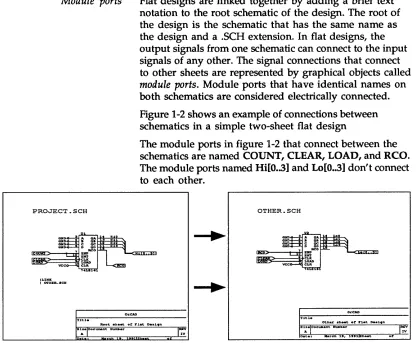
Flat designs are linked together by adding a brief text notation to the root schematic of the design. The root of the design is the schematic that has the same name as the design and a .SCH extension. In flat designs, the output signals from one schematic can connect to the input signals of any other. The signal connections that connect to other sheets are represented by graphical objects called
module ports. Module ports that have identical names on
[image:28.504.42.460.75.418.2]both schematics are considered electrically connected. Figure 1-2 shows an example of connections between schematics in a simple two-sheet flat design
The module ports in figure 1-2 that connect between the schematics are named COUNT, CLEAR, LOAD, and RCO.
The module ports named Hi[O • .3] and Lo[O •• 3] don't connect to each other.
OTHER.SCH
S1.I:. Doc~.nt Nua ... r REV
A N
Size DOCWMlnt NwnlIoer REV
A N
Figure 1-2. Module ports used to link one schematic to another.
Notice the I LINK command (pronounced "pipe link") on the PROJECT.SCH worksheet in figure 1-2. This command is used to tell which worksheets the module ports link to.
It is described on the next page.
I LINK command
When to use a flat design
I Inpu t..name
>
< Out put ..name
<Bidirectional>
IUnspec i of' i ed
Input module port
Output module port
Bidirectional module port
Uhspeciof'ied module port
Module ports indicate the names of the signals to connect but do not specify which schematics are to be included in the design. Therefore, flat designs must have one other component: a list of the worksheets in the schematic. This list appears on the root schematic, and consists of the "pipe" character (the vertical bar on your keyboard) followed by the keyword "LINK", followed by subsequent lines containing the pipe character and the filenames of the worksheets to link to the root sheet.
The example below shows text as it would appear on a schematic that has module ports that link to schematics called SCHEM1.SCH, SCHEM2.SCH, AND SCHEM3.SCH. This text can appear anywhere on the worksheet.
ILINK
I SCHEM1.SCH
I SCHEM2.SCH
I SCHEM3.SCH
NOTE: For details about module ports, see the PLACE
Module Port command in the Schematic Design Tools Reference Guide. For details about placing text on a
worksheet, see the PLACE Text command in the
Schematic Design Tools Reference Guide.
Hierarchical designs
How signals enter and leave sheet symbols
Instead of using a flat design, you can draw schematics that contain symbols representing other schematics. These symbols are called "sheet symbols." The layered
arrangement created by placing schematics inside other schematics is called a hierarchy. Any hierarchy-whether it is a corporate organizational chart or a schematic design-has "higher" and "lower" levels.
Schematic A
Schematic B
Any schematic can contain sheet symbols that reference other schematics, and this nesting structure can be made many levels deep. The schematic at the top of a
hierarchy, which directly or indirectly references all other schematics in the design, is called the root sheet.
You place sheet symbols in a schematic using Draft's PLACE Sheet command.
Just as signals are conducted between schematics through module ports, they are conducted into and out of sheet symbols through graphical objects called sheet nets.
These are the small black objects shown on the borders of the sheet symbols in figure 1-3.
You place sheet nets using Draft's Add Net command, which becomes available when you select the PLACE Sheet command.
The sheet nets on a sheet symbol correspond to module ports on the associated schematic. To associate a
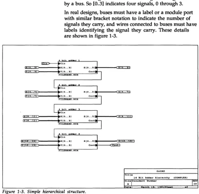
The bracketed notation shown on the module ports and nets [m .. n] designates the number of signals being carried by a bus. So [0 . .3] indicates four signals, 0 through 3.
In real designs, buses must have a label or a module port with similar bracket notation to indicate the number of signals they carry, and wires connected to buses must have labels identifying the signal they carry. These details are shown in figure 1-3.
Cin
I X : I J L : : I D - - - - 4 X [ 0 •• 31
YEO •• 31
S [0 •• 3 1 1 M - - - a n : ; : : : ; : m
Cout
FILENAME. SCH
y 4 •• 7
Cin
X[O •• 31 S [0 •• 31
8 •• Y[0 •• 31 Cout
FILENAME. SCH
Cin
X[O •• 31 S [0 •• 31
.. s YEO •• 31 Cout out
FILENAME. SCH
OrCAD
Title
16 Bit Adder Hierarchy (COMPLEX)
Size Document Number REV
A N
9 S
[image:31.507.40.450.90.488.2]Hierarchies can access the same logic repetitively
How sheet symbols reference schematic logic
The diagram shown in figure 1-3 shows a one-to-one correspondence between sheet symbols and the schematic diagrams they reference. This structure is called a simple
hierarchy.
But what if you have a design in which the logic from a particular schematic must be used in several places? Is each sheet symbol representing the logic required to reference a separate schematic, even though they are identical?
Schematic Design Tools can reference a single schematic from more than one sheet symbol. All you have to do is mark (in the schematic) all the desired sheet symbols with the same filename, the filename of the schematic to reference. This structure is called a complex hierarchy.
To get a sheet symbol to access the logic of a particular schematic, you "mark" the sheet symbol with that schematic's filename. This mark displays at the bottom of the sheet symbol, as shown in figure 1-3.
You "mark" the sheet symbols using the Filename command, which becomes available when you select the PLACE Sheet command.
In addition to their filename markers, sheet symbols also have names of their own. They are used to identify them on their own schematic. In figure 1-3, the sheet symbol names are shown just above each sheet symbol.
Moving between levels in a hierarchy
More about hierarchical design structures
Draft makes it easy to move up and down in hierarchies, from sheet symbol to associated schematic and back again.
To go from a sheet symbol to the associated schematic, put the pointer on the sheet symbol, and select QUIT Enter Sheet. To go from the schematic back to the schematic in which it is referenced by a sheet symbol, select the QUIT Leave Sheet command.
The schematic represented by a sheet symbol can itself have a sheet symbol within it. This means hierarchies many levels deep can be created, each level containing progressively more detail.
This is particularly useful for very complex designs. It
encourages a logical, function-oriented approach to partitioning them, and makes them easier to manage. Another advantage offered by hierarchical structure is the ability to use sheet symbols to repeatedly reference "stock" schematics containing common circuit functions. This is used in gate array and FPGA designs.
NOTE: Designing a deep hierarchy is much more efficient than designing a wide hierarchy. A wide hierarchy, while not a flat design, has many of the limitations in organization, presentation, and structure that flat designs have. A deep hierarchy lets the functional nature of the design be represented and presented more clearly.
For more information, study the hierarchy examples in
Learning
Schematic Design
Tools
Chapter 2: Introducing Schematic Design Tools
Chapter 3: Capturing the clock oscillator schematic
Chapter 4: Capturing the power regulator schematic
The remainder of the Schematic Design Tools User's
Guide shows how to design schematics by guiding you
through the process of creating the schematic diagrams for a digital clock. To do this, you use the schematic editor called Draft to create the schematic of the clock circuitry. Within the schematic are three smaller circuits:
.:. A clock oscillator circuit .:. A power regulator circuit .:. A logic and display circuit
Each of the remaining chapters builds on the skills and concepts from the previous chapter. As you complete each chapter, you create a series of working files.
The summary below describes the design concepts and skills you learn in each chapter.
This chapter introduces Draft, the Schematic Design Tools schematic editor. You learn how to run Draft, change default work conditions settings, select sheet size, change view and display options, and save your
schematic.
In this chapter you create (or capture) a small schematic and learn the basic procedures required for schematic capture. You learn how to get and place library
components, how to draw wires, how to place junctions, and how to place labels and text.
Chapter 5: Creating a custom component
Chapter 6: Capturing the logic and display circuit schematic
Chapter 7: Using other Schematic Design Tools
Chapter 8: Structuring your design
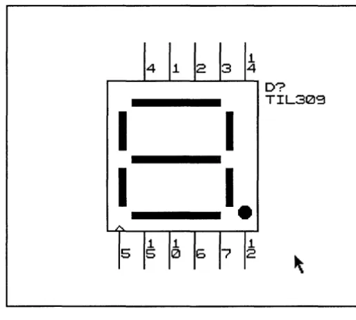
In this chapter you use the Edit Library tool to define a custom component (a seven-segment display). You learn how to draw the part body, draw special shapes, use shading, add pins to the part body, add pin names, and save the new part in a library.
In this chapter you capture the final portion of the digital clock schematic. You learn how to draw a repeatable portion of the schematic, make and place multiple copies of it, write and use a macro, and use repeat parameters to place wires and labels.
This chapter introduces you to some of the other tools included in Schematic Design Tools. You learn to use the Annotate Schematic tool, the Check Electrical Rules tool, the Create Netlist tool, the Back Annotate tool, the Create Bill of Materials tool, and the Plot Schematic tool.
In tro
d
u cing Draft
Before
you
begin
In this chapter, you establish Draft's work conditions. You learn to:
.:. Run Draft, the schematic editor .:. Change default configuration settings .:. Change view and display options .:. Define and save an initial macro .:. Save your work
.:. Structure circuit designs in different ways
Before you begin the exercises presented in this part of the user's guide, take a minute to review the conventions used in this user's guide, and to learn some operating system basics.
Keys Schematic Design Tools is designed to operate on a wide variety of computer systems. Since many computers label
1~~!!!!]!i~ their keyboard keys differently, OrCAD has adopted
MD
~>
standards to name two of the most widely-used keys.<Ctrl>
Other keys
Keyboard input
Operating system command prompt
Throughout the user's guide, you are instructed to enter text. For example, the instructions may read, "Enter the filename." This means to type the name of the file and press <Enter>. If you are instructed to "Type the following characters," you should type the specified characters
without pressing the <Enter> key.
Whenever you see <Ctrl> it means to hold down the <Ctrl> key and press another key. For example, if the instructions say press <Ctrl> <A>, you should hold down the <Ctrl> key and press the <A> key.
Other keys (such as <End>, <F1>, <F2>, etc.) can be shown in angle brackets. In addition, single characters or numbers are also shown in angle brackets (for example, <A> or <1».
Text for you to enter is shown in two ways:
.:. As bold text in typewriter font. For example, "enter tutor.sch"
.:. As bold text in typewriter font enclosed in a box. For example,
Itutor.sch
or
Iload file? tutor.sch
In the examples above, you only enter the characters shown in bold. The non-bold characters show what is displayed on the screen.
In this user's guide, the operating system command prompt is shown as:
Filenames
Designs
Filenames can be from one to eight characters long. If
desired, a filename can be followed by a period and up to three characters for an extension. You can use either uppercase or lowercase letters when entering a filename, but the operating system converts all the letters to upper case. Most of the instructions in this manual use lowercase file names.
Filenames usually contain only letters and numbers. You can use additional characters supported by the operating system. For best results, use letters (A-Z) and numbers (0-9) and limit special characters to under-score (_), pound sign (#), and at sign (@) for compatibility with OrCAD's environment.
Most OrCAD software works with any characters your operating system supports. Some applications used in conjunction with OrCAD software support a more limited character set than what the operating system supports. These include Spice programs, some PCB layout programs, and some text editors.
In the OrCAD design environment, all files pertaining to a design are kept in one directory on your disk. Putting different designs in different directories lets you organize your files, much as you would organize a file cabinet. By following the steps in this tutorial, you will be working on a design called "TUTOR." All of the files for this design are contained in the directory called
Running ESP
To run an OreAD tool, you must first display the design environment screen. To do this, follow these steps: 1. Be sure that your computer is turned on.2. At the operating system prompt, enter the command shown in bold:
!c:>
OReADIn a moment, the design environment screen displays:
~ EDA Tool" ~ATE 0.,,1gn E:SP V>c.)()(
Tool eet.
Sc:honn.tic o...iWl P r c x I r _ I . l..o1aic: Tool. 0."i1ll'" Teols
"
DJ.9,it.l SJtnUl .. ti.cn F"C Be""'" L--..t Tool. Toel.
I
D<1t ESPII
O"'i .... ~ntI
Toel.
OrCAI1
M
Copwr-iQht 1 _ o.-CAO L.P. ~L RIGHTS RE:SERVEO.
Changing to the
TUTOR design
Before you do any work with any of the tools accessed from the design environment screen, you need to change to the TUTOR design. Remember, a design is a directory in which all the files related to a project are stored.
1. Place the pointer on the ti tie bar at the top of the work screen and click the left mouse button.
Design Management Tools Design Management Tools Suspend to System Exit
The menu shown above displays.
2. The Design Management Tools command is
highlighted. Oick the left mouse button again. This selects the Design Management Tools command. The screen shown below displays.
Current Design : TEMPLATE @DeSign View OFile View Design
, ••• iilfiii
TUTOR
~--~---~ Total Size : 40821
Design Files
~ *ESP_OUT.TXT
§] ~~:~~
FILES.LST
MACR01.MAC MACR02.MAC
ORCADESF'.DAT
~
SDT.BCF~ SDT.CFG
Last Modi~ied : 03-19-91 00:00 Description ' - 1 - - - ,
Design management tools screen.
3. Place the pointer on the design named TUTOR and click the left mouse button to select the TUTOR design.
4. Click OK to return to the design environment screen. Notice the heading in the upper center of the screen has changed to TUTOR Design.
Change the start up design
The design environment is configured to display the TEMPLATE design directory each time you run OrCAD tools. Since you will be working in the TUTOR design throughout this guide, you need to change the start-up design to TUTOR.
1. Click on any of the tool buttons that display on the design environment screen. The menu at right displays.
Schematic Design Tools Execute
Local Configuration Configure ESP Help
2. Select Configure ESP. The screen below displays:
Cc:>nf" 1 9Y"'''' E:SP
I
OKI
I
c.nc .. lI
~
- 00- i vet"" Opt ion.
Or i vvr Pr.,f'i>< Ic: 'ORCAOESF"-.DRV'. I
Av.i labh. 01..,,1_ Oo-ivtrrtO R"""olution Color .. Adapt..r Namw
I
640 )( 350 .1
=~·Q··~'-II
Con4'lgc.r.d 01 .. ,.,1_ Orlv.ro IECA2.ORV
I
r;:
Edi tor Opt ion.2..e><t Edi tor I
First part of the Configure ESP screen.
II
3. Move the pointer to the bottom of the screen. The display pans to show more of the Configure ESP screen. Continue panning until you reach the Design Options section.
Design Options
Startup Design ITEMPLATE
4. Place the pointer in the Startup Design entry box and click the left mouse button. Use the <Backspace> key to delete TEMPLATE. Enter TUTOR as the startup design.
Design Options
Running
Schematic Design
Tools
5. Move the pointer to the top of the screen and dick the OK button. An easy way to get to the OK button is to press the <Home> key.
The changes you made to the Configure ESP screen are saved and the design environment screen displays.
NOTE: Refer to the OreAD jESP Design Environment
User's Guide for detailed instructions on how to configure
ESP.
Follow these steps to display the Schematic Design Tools screen.
1. Point to the Schematic Design Tools button and click the left mouse button. The menu at right
displays.
Schematic Design Tools Execute
Local Configuration Configure ESP Help
2. Select the Execute command. The Schematic Design Tools screen displays:
Schemati~ Design Tools TUTOR Ottsign ESP V><.><>< ,..-E:ditOl"" P,....oc:est&0r"""5 rT,..ansf'.,... ..
-EJ
I
Cr • • t . Net! i s t1
~
PLD~tat.
IEdit F"il"'l
Scnematie
er-•• t . ~~ Oi.9it.1 I·U"',...:hical Nltt I i .. t i ... l.ticr
I
6ac:k1
'FO'
V.i«"w Upd"te Annat at .. ~
Re.f'e,..",nce F"i.ld CI",anup Mat .. ,..ial Content.
II Sel",ct Sc:httona t ie:
I
To Main 1It
llf"i.ld Vi...,
, - - - - L i b r -.... i...,. R.por-t.,... U s e , . .
-Edit List Cros. c.-..t. Chorc:k
EJ
Libr-arlo! Libr-.... !oj R.-r ... nc:. Bill o.f' E:l.ct ... i~.lE:J
P .... t . H.t.rial. Rul • •
I
CoIrf:>ileI
o.~ompil. PlotEJ
Libr-arw Libr-ar-\,j SckotrnAt ie
Shoo..i Conv.,...t
I
I
D • • ign Plot to
EJ
Str-uctur", lGES
Arc:kiv .. P..-ts Print
Defining title block
information
View Schematic Design Tools' configuration
Before you run the schematic editor Draft, take a few minutes to define the information to appear in the title block of the worksheet you will create. To do this, you must display the Schematic Design Tools configuration screen.
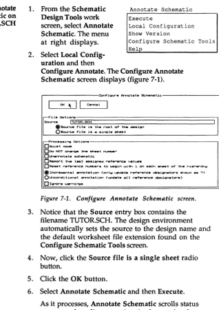
1. From the Schematic Design Tools screen, click the Draft button.
Draft Execute
Local Configuration
2. Select Configure Sche-matic Tools from the menu that displays.
Show Version
Configure Schematic Tools Help
The figure below shows the first part of the Configure Schematic Design Tools screen. The parameters you see may vary, because some of the configuration information depends on your system hardware. For more information about the Configure Schematic Design Tools screen, see Chapter 1: Configure Schematic Tools in the Schematic Design Tools Reference Guide.
OK ~
I I
Can<=_"'_l---l
r-~iv~~ti~---Driver F'o-e~ix Ic: 'ORC:::::AD!:::!:E=S:::...P'~[)RV'..~ _ _ _ _ _ _ _ _ _ _ _ _ _ _ _ _ _ _ _ _ _ ---J
Avai l a b t . Oispl~ Dr-i~
Resolution Color-s ~i: ... Name
640 )( 200 2 Color Graochics ~t..,.. G
~:~ ~ ~= ~~ ~;~':'~i~~er ~
640 )( 360 1 EGA 1100...J. 01 .... meni tor ~
640 )( 360 4 EGA (641( _>
640 )( 350 16 ECA Erl->anc:ed meni tor v ConT'igured Oi .. " I _ Drlv.rlvGA11S.0RV I
A ... aila~le F>rini:er Dri...-s
Manuf'ac:tL ... r Model Re.solution
AMT ACCEL-500 120 >< 120 G
g: r::~ ~~~~/B510 ~~ : i~ ~
~:!~rOc:k..lc:t .. 8012 1~ ~ 1~ @ E", .. on MX 120 )( 216 G
Conf'igured Printer Driver IEPSONMX.DRV I
Available Plott...- Dri...-s
M~f'~t~~~&~~~I~ ___________________ - ,
I
calC:omp (Into.llig&!nt)13
Calc: ... (Non-Int.lli_nt> IAl3. Pan to the Worksheet Options area (shown below).
Wor-kSkeRt O P t l . o n s - - - ,
DANSI t i t l .. blcx:k
DANSI g-id ... f' ... nQIr.
DU-altar-nata wor-kskeort ... f'i><
I .... I wi t p p. ,
DeT ... l t WCII'"'k_ .. t 4'11 .. "Ht .. nsion~
s.--.t .. iz.. ~
~t~ ~,=---~
Revision c::J
T i t l . ; = , = - - - ,
<lr-9."iz.tion ... ,
Qrganiz.tion ac:Ic:Ir_ .. : = , ============~
,
Worksheet Options area of Configure Schematic Design Tools screen.
4. Notice the Document number, Revision, Title, Organization name, and Organization address entry boxes. Any information entered in these fields becomes a part of your worksheet's title block. For this
tutorial, you enter information in the Title,
Organization name, and Organization address entry boxes.
Position the pointer within the Title entry box and press <Enter> or click the left mouse button. The pointer becomes a cursor inside the entry box. Enter the title: Digital clock schematic.
Press <Tab> to move to the next entry box, in this case, Organization name.
Press <Enter>.
5. Enter the name and address of your organization in the Organization name and Organization address entry boxes.
6. To update the configuration and return to the
Schematic Design Tools work screen, move the pointer to the top of the screen and click the OK button.
Running Draft
Now that you have selected the TUTOR design and set up your title block information, you are ready to begin learning about the schematic editor Draft.1. Click the Draft button. The Draft menu displays. 2. Select Execute.
Draft is now running. The top and left edges of the sheet are displayed. Because the screen is smaller than the worksheet, the right and bottom edges of the worksheet are not visible. You can think of the screen as a window into the larger worksheet area.
«<New Worksheet»>
DrCAD basics
Mouse basics
y
Display the main menu
Pop-up menus written in plain English guide you from step to step in OrCAD software. Draft organizes commands using menus and command lines. You can select a command by either clicking the mouse or pressing a key. (For complete command descriptions, refer to the Schematic Design Tools Reference Guide.)
.:.
Clicking the left mouse button is the same as pressing the <Enter> key. In this user's guide, when you are instructed to "press <Enter>," you can use either the keyboard or the mouse, whichever you prefer..:.
Clicking the right mouse button is the same aspressing the <Esc> key. In this user's guide, when you are instructed to "press <Esc> ," you can use either the keyboard or the mouse, whichever you prefer.
To display Draft's main menu, (shown at right) press <Enter> or press the left mouse button. To remove the main menu from the screen, press <Esc> or click the right mouse button.
Follow the steps below to display and remove the main menu. 1. To see the main menu, press
<Enter>.
2. To remove the main menu from the screen, press <Esc>.
3. To see the main menu, click the left mouse button.
4. To remove the main menu from
Again Block Conditions Delete Edit Find Get Hardcopy Inquire Jump Library Macro Place Quit Repeat Set Tag Zoom
Commands
Selecting commands
Menus
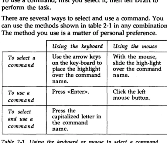
To use a command, first you select it, then tell Draft to perform the task.
There are several ways to select and use a command. You can use the methods shown in table 2-1 in any combination. The method you use is a matter of personal preference.
Using the keyboard Using the mouse To select a Use the arrow keys With the mouse, command on the key-board to slide the high-light
place the highlight over the command over the command name.
name.
To use a Press <Enter>. Click the left
command mouse button.
To select Press the
and use a capitalized letter in command the command name.
Table 2-1. Using the keyboard or mouse to select a command.
Draft responds to a command by either performing the command's function or displaying another menu or a command line.
All menus look and work just like the main menu. Draft displays the menu name on the top line of the screen. Press <Esc> or the right mouse button to return to the menu or command line that called the current menu.
1. Press <Enter> to display the main menu.
2. Select the BLOCK command. Notice that another menu displays. The BLOCK menu is shown at right.
3. Press <Esc> to return to the main menu.
Block
Move
Drag Fixup Get
Save
[image:47.507.171.446.78.314.2]Command lines
How command names are shown in this guide
Return to the main
menu
Command lines are a series of command names listed across the top of the screen. When a command line displays, you can move the pointer around the working area or select a command. Press <Esc> or the right mouse buttonto return to the menu orcommandline that called the command line.
1. Press <Enter> to display the main menu. 2. Select the EDIT command.
Notice a command line displays across the top of the screen. The EDIT command line is shown below.
IEdit Find Jump Zoom
3. Press <Esc> to return to the main menu.
In this guide, main menu command names are shown in uppercase letters. Other command names are shown with just the first letter capitalized. When you are asked to select a command, usually both the main menu command name and other command name are specified.
For example, the statement, "Select the PLACE Wire command" means, "Select the PLACE command from the main menu, and then from the resulting PLACE menu, select the Wire command."
Sometimes, when the context is clear, the main menu command is not specified. For example, if the PLACE menu is already displayed, and you are asked to select the Wire command, the instruction is simply, "Select the Wire command."
Setting up Draft's
work conditions
Disp lay work conditions settings
Auto Pan
Now that you understand how Draft's commands, menus, and command lines operate, you will use the SET
command to change the default work conditions that govern the way Draft displays and maintains schematics.
1. Press <Enter> to see the main menu.
2. Select SET from the main menu. The SET menu appears, as shown below.
Using the commands in the SET Set
.---~
menu, you can control features such as automatic backup of schematic files, the angles at which you can draw wires, and whether or not pin numbers display on component symbols. For more information about Draft's work conditions, see the SET command description in the
Schematic Design Tool Reference Guide.
The next few paragraphs de-scribe a few of Draft's work conditions and the commands controlling them.
Auto Pan YES Backup file YES Drag Buses NO Error Bell YES Left Button NO Macro Prompts YES Orthogonal YES Show Pins YES Title Block YES Worksheet Size A X,Y Display NO Grid parameters Repeat parameters Visible Lettering
Auto Pan is the first command in the SET menu. When you start work on a new worksheet, Auto Pan is set to Yes.
When Auto Pan is set to Yes, the worksheet follows the movement of the pointer. If part of a worksheet is off the screen and you move the pointer beyond the edge of the display, the hidden part of the worksheet pans into view.
Pan across the schematic
Redisplay the SET menu
X,Y Display
1. Press <Esc> to remove the SET menu from the screen. Auto Pan remains set to Yes.
2. Move the pointer to the lower right corner until the title block appears. The screen pans to keep up with the pointer. Notice the title block information that you entered earlier in this chapter.
3. Move the pointer toward the upper left-hand corner until the upper left comer of the worksheet displays.
1. Press <Enter> to recall the main menu. When the menu displays, you'll see the highlight bar is on the AGAIN command.
2. Press <Enter> to select AGAIN. This selects the main menu command you chose last-in this case, SET.
A coordinate system is used to locate points on the worksheet, as shown in the illustration below.
An X coordinate specifies horizontal location and a Y coordinate specifies vertical location.
0.00,0.00
+
2.00,1.00+
1.00,2.00x
...
Thus any point on the worksheet can be indicated by an X and Y coordinate
+ 4.00,3.00
pair in the form (X,Y). The (0.00,
0.00) point is always at the upper left of the worksheet.
Set X, Y display to YES 1. Select X,Y Display.
Worksheet size
Select worksheet size
"Display X,Y Coordinates of Cursor?" and a short menu appear.
2. Select Yes. The menu disappears.
3. Move the pointer in any direction and watch the X,Y coordinates in the upper right corner of the screen.
The units shown in the X,Y display are inches on the printed schematic. The upper left corner is (.00, .00) and the lower right corner is (9.50, 7.00). So, on a sheet 8.5 inches by 11 inches, the drawing area is 7 inches by 9.5 inches to allow borders around the drawings.
The Worksheet Size command selects one of five sizes for your schematic.
1. Display the main menu, then select AGAIN. The SET menu displays.
2. Select Worksheet Size. A Set Worksheet size
menu displays the five options (Area inside borders)
available for the size of a A 9.50 x 7.00
worksheet, as shown at right. B 15.00 x 9.50
3. Select C size.
4. Move the pointer to the edges and corners of the worksheet
C 20.00 x 15.00 D 32.00 x 20.00 E 42.00 x 32.00
to explore the size of the editable region of a C-size sheet. The dimensions shown in the Worksheet Size menu are the dimensions of the worksheet's borders. On a C-size sheet (actually 22 inches by 17 inches), the drawing area is 20 inches by 15 inches.
Changing
your
view of the
worksheet
ZOOM in and out
Draft can display worksheets at five different scales. You change the view using the ZOOM command. The
worksheet can be zoomed in or out to magnify or reduce its visible image.
When Draft is zoomed out, you can see a large portion of the worksheet. Zooming in enlarges a small portion of the worksheet and displays more details. You can zoom in to draw intricate portions of your worksheet with exacting detail and then zoom out to look at the finished
schematic.
To zoom out and see more of the worksheet on the screen at one time, follow these steps:
1. Move the pointer to lower right corner until the title block appears.
2. Select ZOOM from the main Zoom (present scale=1)
menu. The ZOOM menu at Center 1)
right appears. In 1)
Out 2)
3. Select Out. A view of the Select worksheet at one-half the
original scale displays.
4. Experiment with the scale using In, Out, and Select. If
you use Select you can choose the scale at which to view the worksheet, as shown in the figure below.
If you choose 1, you view the worksheet at full size. This shows the most detail ("zooms in" the farthest). If
you choose 2, you view the worksheet at one-half the original scale. If you choose 20, you view the worksheet
Zoom - Select Scale (present scale=1)
1
2 5
10 20
at one-twentieth the original scale. You see the maximum working area and the least detail.
Grid parameters
Display grid references
Stay on Grid
While working on a large worksheet, it is useful to have visual cues that tell you approximately where you are on the sheet.
The Grid Parameters com-mands on the SET menu let you set up some of these visual cues. Grid Parameters contains the three commands shown at right.
Set Grid Parameters Grid References No Stay On Grid Yes Visible Grid Dots No
Grid References turns grid reference guides along the top and left edges of the display on and off. The guides divide the worksheet into blocks. Horizontally, the grid guides divide the worksheet from 8 to 1. Vertically, the guides divide the worksheet from D to A. For example, the title block (lower right corner) is located at A-I. You use JUMP Reference to move to specific locations using these map-like coordinates.
1. Select SET from the main menu to change the grid display.
2. Select Grid Parameters.
3. Select Grid References, then select Yes. The grid reference bars appear at the top and left edges of the display.
NOTE: Schematic Design Tools can be set up to use ANSI
Y14.1 drawing standards. Refer to the Schematic Design
Tools Reference Guide for details.
Stay on Grid determines whether or not pointer movement is restricted to grid intersections. Stay On Grid is set to YES. Do not make any changes here.
Make the grid visible
Updating the
worksheet
Update the file
Visible Grid Dots turns the dots representing intersections on and off. The space between the dots represents 0.1 inch on the printed worksheet.
1. Select SET and Grid Parameters again.
2. Select Visible Grid Dots, then select Yes. Grid dots appear on the worksheet. You may want to adjust the intensity on your monitor to make the grid dots brighter or dimmer.
When you work on a schematic for a long time, it is important to save your work on disk periodically as a precaution against power failures and other unexpected events.
To save the worksheet without changing its filename, follow these steps:
1. Select QUIT from the main menu.
Quit TUTOR.SCH Enter Sheet Leave Sheet Update file
Draft displays the filename and the QUIT menu, as shown at right.
2. Select Update File. Draft saves the file.
Write to file Initialize
Suspend to System Abandon Edits
Creating a macro
Macros can record virtually anything you do in aprogram-so you can automate many repetitive tasks and speed up your work. Earlier in this chapter, you used the SET command to change work conditions parameters. To capture these commands in a macro that can be repeated each time you press <Ctrl> <A>, follow these steps: 1. Select MACRO from the main Macro
menu. The MACRO menu is shown at right.
, . . - - - -... Capture
Delete Initialize
2. Select Capture to record a List
macro. The prompt "Capture Read
macro?" appears. You can Write
'---...1
assign a number of keys and
key combinations to run macros. Single keys that can run macros are the function keys «Fl> - <FlO» and keys in the numeric keypad with text on them such as <Home>, <Page Up>, and <Page Down>. Key
combinations that can run macros include: .:. <Ctrl> + function keys
.:. <Ctrl> + alpha keys (except C, H, and M) .:. <AI t> + function keys
.:. <Alt> + alpha keys .:. <Shift> + function keys
If you choose a prohibited key combination, Draft rejects it.
3. To assign a keystroke to this macro, press <Ctrl><A>.
"A appears at the "Capture Macro?" prompt.
Save the macro
5. Type the commands in the left column below:
<Enter>
s
X YResponds to the "load file?" prompt
Commands to see the X, Y coordinates
S G G Y
S G V Y
Z S 1
Commands to see grid references
Commands to see the grid dots
Commands to set the viewing scale to full size ("zoom in" to the most detail).
6. Press <Ctrl><End> to end the macro definition. Draft confirms the macro definition is complete by
displaying:
I«<MACRO END»>
The macro is now stored in the computer's memory. You can run it anytime by pressing the key
combination you specified, <Ctrl><A>.
NOTE: Some keyboards have two keys labeled <End>. On a few of these, you must use the <End> key in the numeric keypad.
Now, save the macro in a file.
1. Select MACRO Write. Draft displays:
IWrite all macros to?
2. Enter tutor .mac.
Exiting Draft
3. To tell Draft to read macros from the TUTOR.MAC file, select MACRO Read. Draft displays:
IRead all macros from?
4. Enter tutor. mac.
5. To test the macro you just saved, change some of the work conditions parameters and press <Ctrl><A> to restore the work conditions.
You are nearly done with this chapter. To exit Draft, follow these steps:
1. Select QUIT from the main Quit TUTOR.SCH
menu.
Draft displays the filename and the QUIT menu shown at right.
2. Select Update File. Draft saves the file.
3. Leave Draft by selecting
Enter Sheet Leave Sheet Update file Write to file Initialize
Suspend to System Abandon Edits Run User Commands
Setting up
automatically
View the configuration
In addition to using SET to control Draft's work
conditions, you can automate the process of defining Draft work conditions parameters by configuring Schematic Design Tools so that the