Towards Implementation of Smart Grid: An Updated
Review on Electrical Energy Storage Systems
Md Multan Biswas1*, Md Shafiul Azim2, Tonmoy Kumar Saha2, Umama Zobayer3, Monalisa Chowdhury Urmi3
1Department of Electrical and Electronic Engineering, Bangladesh University of Engineering and Technology, Dhaka, Bangladesh; 2Department of Electrical and Electronic Engineering, Khulna University of Engineering and Technology, Khulna, Bangladesh; 3Department of Electrical and Electronic Engineering, Stamford University Bangladesh, Dhaka, Bangladesh.
Email: *[email protected]
Received November 27th, 2012; revised December 26th, 2012; accepted January 4th, 2012
ABSTRACT
A smart grid will require, to greater or lesser degrees, advanced tools for planning and operation, broadly accepted communications platforms, smart sensors and controls, and real-time pricing. The smart grid has been described as something of an ecosystem with constantly communication, proactive, and virtually self-aware. The use of smart grid has a lot of economical and environmental advantages; however it has a downside of instability and unpredictability introduced by distributed generation (DG) from renewable energy into the public electric systems. Variable energies such as solar and wind power have a lack of stability and to avoid short-term fluctuations in power supplied to the grid, a local storage subsystem could be used to provide higher quality and stability in the fed energy. Energy storage sys- tems (ESSs) would be a facilitator of smart grid deployment and a “small amount” of storage would have a “great im- pact” on the future power grid. The smart grid, with its various superior communications and control features, would make it possible to integrate the potential application of widely dispersed battery storage systems as well other ESSs. This work deals with a detailed updated review on available ESSs applications in future smart power grids. It also high- lights latest projects carried out on different ESSs throughout all around the world.
Keywords: Battery; Distributed Generation; Hybrid Energy Storage Systems; Power Quality; Smart Grid
1. Introduction
The world’s electricity systems face a number of chal- lenges, including aging infrastructure, continuous in- crease in demand, the integration of growing numbers of variable renewable energy DGs and electric and hybrid electric vehicles, the need to improve the security of power supply, and the need to lower carbon dioxide (CO2)
emissions [1-3]. These challenges must be addressed also with regard to each region’s unique technical, economic, and commercial regulatory environment [4]. Smart grid technologies offer ways not just to meet these challenges but also to develop a sustainable energy supply that is more energy efficient and more affordable.
Compared to other industries, our electrical grid has been largely bypassed by technological innovation until relatively recently, owing to the fact that historically it has been heavily regulated and modeled to keep the lights on and costs low. Partly for this reason, its mod- ernization by means of information-technology tools and
techniques has been somewhat of a back-burner priority. Like the telecom and internet revolutions that preceded it, technology holds the key to the smart grid and its realiza- tion. The smart grid and the technologies embodied with- in it are an essential set of investments that will help bring our electric grid into the 21st century using mega- bytes of data to move megawatts of electricity more effi- ciently, reliably, and affordably [5-9].
The smart grid will:
Provide power quality for the digital economy; Accommodate all generation and storage options; Enable new products, services, and markets; Optimize asset utilization and operate efficiently; Enable active participation by consumers; Anticipate and respond to system disturbances; Operate resiliently against attack and natural disaster.
Storage is perhaps the most important smart grid ad- vanced component because of its key role in comple- menting renewable generation. With the proper amount and type of storage broadly deployed and optimally con- trolled, renewable generation can be transformed from an energy source into a dispatchable generation source
[10-12]. And with the addition of energy storage, more wind and solar generation can be added to a typical po- wer system that employs a large percentage of slow-re-sponse fossil and nuclear generation. It is feasible that, the penetration of renewables can be significantly above 20 percent with the addition of sufficient energy storage technologies [13].
This paper is organized as follows. Section 2 presents a brief description of smart grid technology with its es- sential features. The necessity and prospect of energy storage systems in future smart power grid are broadly discussed in Section 3. Finally, Section 4 elaborately re- views the available energy storage technologies that are considered for use in smart grid applications with up- dated technologies, which is followed by some conclud- ing remarks in Section 5.
2. Smart Grid: Technology Description
Though there has been much debate over the exact defi- nition of smart grid, it actually comprises a broad range of technology solutions that optimize the energy value chain. Depending on where and how a specific utility operates across that chain, it can benefit from deploying certain parts of a smart grid solution set. Smart grid is a large electricity network that uses digital and other ad- vanced technologies to improve efficiency, reliability, and security of the electric system: from large generation, through the delivery systems to electricity consumers and a growing number of distributed-generation and energy storage resources [14-16]. Smart grids co-ordinate the needs and capabilities of all power generators, grid op- erators, end-users, and electricity market stakeholders to operate all parts of the system as efficiently as possible, minimising costs and environmental impacts while maxi- mising system stability, reliability, and resilience. Smart grids are an evolving set of technologies that will be de- ployed at different rates in a variety of settings around the world, depending on local commercial attractiveness, compatibility with existing technologies, regulatory de- velopments, and investment frameworks. Figure 1 de-monstrates the evolutionary character of smart power net- work [4].
Advanced metering infrastructure (AMI) is an ap- proach to integrating consumers based upon the devel- opment of open standards. It provides consumers with the ability to use electricity more efficiently and provides utilities with the ability to detect problems on their sys- tems and operate them more effectively [17,18]. AMI enables consumer-friendly efficiency concepts like “Prices to Devices” to work like this: Assuming that energy is priced on what it costs in near real-time—price signals are relayed to “smart” home controllers or end-consumer devices like thermostats, washer/dryers, and refrigera- tors—the home’s major energy-consumers [19-21]. The
devices, in turn, process the information based on con-sumers’ learned wishes and power accordingly. The house or office responds to the occupants, rather than vice-versa. Because this interaction occurs largely in the background with minimal human intervention, there’s a dramatic savings on energy that would otherwise be con- sumed [14]. Far more than “smart meters,” a fully-func- tioning smart grid will feature sensors throughout the transmission and distribution grid to collect data, real- time two-way communications to move that data be- tween utilities and consumers, and the computing power necessary to make that intelligence actionable and trans-active as shown in Figure 2. Indeed, only by bringing the
tools, techniques, and technologies that enabled the in- ternet to the utility and the electric grid is such a trans- formation possible [8].
Smart Grid’s Principal Characteristics
A smart power grid brings the power of networked, in- teractive technologies into an electricity system, giving utilities and consumer’s unprecedented control over en- ergy use, improving power grid operations, and ultima- tely reducing costs to consumers. In brief, the main fea- tures of smart grids are [9,22-26]:
1) A smart grid accommodates not only large, central- ised power plants, but also the growing array of custo- mer-sited distributed energy resources.
2) Not all commercial enterprises, and certainly not all residential customers, need the same quality of power. A smart grid supplies varying grades (and prices) of power.
3) Correctly designed and operated markets efficiently create an opportunity for consumers to choose among competing services.
4) A smart grid applies the latest technologies to opti- mize the use of its assets. For example, optimized capac- ity can be attainable with dynamic ratings, which allow assets to be used at greater loads by continuously sensing and rating their capacities.
5) Provides resiliency to disturbances, attacks, and na- tural disasters. Self-healing actions result in reduced in- terruption of service to consumers and help service pro- viders better manage the delivery infrastructure.
6) Consumers help balance supply and demand, and ensure reliability by modifying the way they use and pur- chase electricity.
3. Energy Storage—A Key Enabler of Smart
Grid
Figure 1. Smarter electricity systems.
Figure 2. Advanced communication and control in smart
grids. Figure 3. Distributed energy storage in a Windfarm.
High voltage power electronics, such as switches, rec- tifiers, inverters, and controllers, allow electric power to be precisely and rapidly controlled to support long dis- tance transmission [35,36]. Thus, energy storage and power electronics hold substantial promise for trans- forming the electric power industry [28]. This capability will allow the system to respond effectively to distur- bances and operate more efficiently, thereby reducing the need for additional infrastructure.
various ESSs can be controlled in order to guarantying proper applications. Further, in modern power distribu- tion systems, where a significant amount of the total electricity demand is met by renewable generation, ESSs can mitigate the uncertainties of energy sources (such as solar and wind) and can store the energy during high renewable production and/or low price periods, and de- liver when either necessary or convenient [28-31]. Based on the ESSs technologies, in [27] the applications of ESSs are classified in instantaneous, short-, mid- and long-term. Instantaneous and short-term applications are involved in real time regulations, for example aiming at ancillary services provision or integration of electric drive vehicles batteries in the networks [32,33].
4. Available Energy Storage Systems
The adoption of smart power grid devices throughout utility networks will effect tremendous change in grid operations and usage of electricity over the next two decades. Increased deployment of energy storage devices in the distribution grid will help make this process hap- pen more effectively and improve system performance. The energy storage systems (ESSs) applicable in power networks can be divided into two major categories [29] as shown in Figure 4. The first category being large-
scale storage systems that can be used in utility transmis- sion applications. The second group includes small-scale Energy storage systems improve the efficiency and re-
[image:3.595.64.541.90.425.2] [image:3.595.326.524.287.439.2]storage systems sited at the consumer’s premises. Some of the available energy storage systems are potentially discussed in the following sub-sections.
4.1. Battery
Battery is one or more electrochemical cells that convert chemical energy into electrical energy. Batteries have been using for energy storage purpose for over one-hun- dred years and possess some very important, unique, and desirable features. Battery energy storage systems (BESSs) are modular, quiet, and non-polluting [37]. Bat- teries are manufactured in a wide variety of capacities ranging from less than 100 watts to modular configura- tions of several megawatts. As a result, batteries can be used for various utility applications in the areas of gen- eration, transmission and distribution, and customer ser- vice and they can be installed relatively quickly. Battery has convenient size and voltage characteristics. The op- erating principle of a typical battery is shown in Figure 5.
A grid-scale BESS consists of a battery bank, control system, power electronics interfacing circuit for ac-dc power conversion, protective circuitry, and a transformer to convert the BESS output to the desired transmission or distribution system voltage level [38]. The battery bank consists of numerous batteries connected in a combina- tion series-parallel configuration to provide the desired energy and power capabilities for the application.
[image:4.595.343.503.351.503.2]The use of Lead Acid batteries for energy storage dates back to mid-1800s. There have been developed several new battery technologies to store more energy,
Figure 4. Energy storage systems in smart power networks.
last longer and less cost than the Lead Acid battery. Bat- tery technologies differ widely in terms of their energy and power densities, energy efficiencies, cycle-life, avai- lability, and operating conditions. Some of these new battery technologies are Lithium Ion, Lithium Polymer, Nickel Metal Hydride (Ni-MH), Vanadium Redox (VRB), Nickel Cadmium (Ni-Cd), Sodium Sulfur (NaS), and Zinc Bromide [39-41]. Table 1 summarizes the
characteristic parameters of different batteries [27,28, 42- 44].
4.2. Ultra-Capacitors
Ultra-capacitors (UCs), also known as super-capacitors, or electric double-layer capacitors (EDLCs), store energy in the electrical double layer at an electrode/electrolyte interface. There are no chemical reactions involved in the UC’s energy storage mechanism. The main parts of an electrochemical capacitor are electrodes and electrolyte. The electrical energy E accumulated in ultracapacitors is related to the capacitance C or the stored charges Q and voltage V by following formula:
[image:4.595.73.276.473.718.2]Figure 5. Working principle of a battery.
Table 1. Comparison of different types of batteries.
Type
Energy Density (Wh/kg)
Energy Efficiency
(%)
Power Density (W/Kg)
Cycle Life (Cycles)
Self Discharge (%/Month)
Lead-Acid 30 - 40 70 - 90 180 200 - 2000 3 - 4
Li-Ion 100 - 250 75 - 90 1800 500 - 2000 5 - 10
Li
Polymer 130 - 200 70 3000 >1200 4 - 8
Ni-MH 30 - 80 70 250 - 1000 500 - 100 30
Ni-Cd 40 - 60 60 - 90 140 - 180 500 - 2000 10 - 15
NaS 150 80 - 90 120 - 150 2500 -
VRB 25 - 40 80 100 - 150 >16,000 <1
Zinc
[image:4.595.310.537.535.734.2]2
1 1
2 2
E CV QV (1)
And,
A
Q CV V
d
(2)
As for the conventional capacitor, the capacitance is proportional to the area
C
A of the plates and the per- mitivity of the dielectric ε and is inversely proportional to the distance between the plates. UCs are designed to have a very high electrode surface area and use high permitivity dielectric. Due to the high permeability and close proximity of the electrodes, UCs have a low volt- age withstand capability (usually 2 - 3 V) [30]. The elec- trode surface area is maximized by using porous carbon as the current collector, allowing a relatively large amount of energy to be stored at the collector surface. Therefore, UCs attain very high capacitance ratings. Larger UCs have capacities up to 5000 farads [45].
d
Ultracapacitors store energy by physically separating unlike charges. UCs have a long cycle life due to the fact that there are no chemical changes on the electrodes ide- ally in normal operation and UCs have superior effi- ciency. UCs also provide exceptional power density, since the charges are physically stored on the electrodes. Conversely, energy density is low since the electrons are not bound by chemical reactions [30]. The UC is tem- perature resistant with an operating range between −40˚C to +65˚C and is also shock and vibration resistant [46, 47].
In order to be a viable alternative in a large scale en- ergy storage system they will need to be able to handle multiple kV. The ability of modular, non-polluting, quiet, quick charge and discharge capability, long life (10 to 12 years), and very high cycle life makes the UC a very de- sirable energy storage device. They can be use for short term ride through capabilities as well as voltage regula- tion, frequency control and other power quality issues [47,48]. UCs are currently available in many sizes. Two 3000 F capacitors are shown in Figure 6. There is even a
startup company that claims to be able to create ultra capacitors with higher energy densities than lead-acid, Nickel metal hydride and even lithium ion batteries [49]. There have also been advances in the design of the ultra-capacitors using nano-tube technology to improve the surface area of the capacitor. This “nano-tube ultraca- pacitor” would improve the ultracapacitor’s energy den- sity to be compatible with again that of a chemical bat- tery [46,50,51].
4.3. Flywheel
During the past decade, flywheel energy storage systems (FESSs) have been rediscovered by the power industry
due to their advantages in comparison with other energy storage systems. FESSs have found an important techni- cal role on the application of enhancing the electric power quality, grid voltage and frequency support, and unbal- anced load compensation. By virtue of their high dy- namics, long lifetime, and good efficiency, FESSs are well suited for short-term storage systems [52-54].
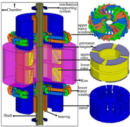
[image:5.595.321.526.313.472.2]FESS consists of a flywheel coupled to permanent magnets synchronous machine (PMSM) as shown in
Figure 7. Flywheels store energy in the form of momen-
tum in a rotating wheel or cylinder. A FESS stores en- ergy through accelerating a rotor up to a high rate of speed and maintaining the energy in the system as iner- tial energy. Advanced composite materials are sometimes used for the rotor to lower its weight while allowing for the extremely high speeds. The flywheel releases the energy by reversing the process and using the motor as a generator. As the flywheel releases its stored energy, the
[image:5.595.309.534.497.718.2]
Figure 6. 3000 farad ultracapacitors.
flywheel’s rotor slows until it is fully discharged. The energy that can be stored depends on its rotational veloc- ity and moment of inertia , as in (3). They have high power density and more energy can be stored if the flywheel rotates at higher rotational speed [55]. Power electronics are used to ensure that output voltage has ap- propriate amplitude and frequency characteristics.
I
2
1 2
E I (3)
Flywheel energy storage systems using superconduct- ing magnetic bearing (SMB) together with a permanent magnet bearing (PMB) is one of the most promising elec- tro-mechanical energy storage systems consisting long life, high energy density, high efficiency, with no pollu- tion or toxic material disposal problems, and low rota- tional loss by non-contact superconductor bearing [55- 57].
Flywheels have seen most commercial success tar- geted for power delivery capabilities typically in the 150 kW-1MW range [50,58]. Recently, a 20 MW FESS plant has been successfully established in Stephentown, New York by Beacon Power Corp. under a pilot project of the Department of Energy (DOE), New York State Energy Research and Development Authority (NYSERDA) and currently 40 MW FESS plant project is under develop- ment [59].
4.4. Superconducting Magnetic Energy Storage (SMES)
Superconducting magnetic energy storage (SMES) sys- tems store energy in the magnetic field produced by cur- rent flowing through a superconducting coil. The SMES principle is based on inductive energy storage in the magnetic field produced by current flowing through a su- perconducting coil.
A SMES system consists of four major subsystems [60], plus miscellaneous equipment for system control, data collection, and so on. The major subsystems are: 1) superconducting coil with magnet (SCM); 2) power con- ditioning system (PCS) that controls the flow of current into and out of the coil to charge and discharge the SMES; 3) cryogenic system (CS) that maintains the coil at a low enough temperature to maintain superconductiv- ity; and 4) the control unit (CU), as shown in Figure 8.
For a SMES system, the inductively stored energy
E and the rated power
P are commonly the given specifications for SMES devices, and can be expressed as follows:2
1 d d
2 ; d d
E I
E LI P LI V
t t
I (4)
where L is the inductance of the coil, I is the dc current flowing through the coil, and V is the voltage across the
coil. During SMES operation, the magnet coils have to remain in the superconducting status. A refrigerator in the cryogenic system maintains the required temperature for proper superconducting operation [61].
Among the different variants of flexible alternating current transmission system (FACTS) devices and ESSs
currently available, static synchronous compensators (STATCOM) integrated with SMES has been proposed as the most adequate for participating of the primary frequency control because of SMES has high efficiency (95% to 98% [61]) and rapid response to power demand [62-64]. Depending on the control loop of its power conversion unit and switching characteristics, the SMES system can respond very rapidly (MWs/milliseconds). The ability of injecting/absorbing real or reactive power can increase the effectiveness of the control, and enhance system reliability and availability. Comparing with other storage technologies, the SMES technology has a unique advantage in two types of applications: Power system transmission control and stabilization, and power quality improvement [65].
Several SMESs in the range of kWh to MWh scale have been already implemented for compensation of load/ generation fluctuation as well as energy storage [66]. Recently, 10 MVA/20 MJ SMES prototype has been test- ed at an actual power system including hydro power ge- nerators in order to compensate the fluctuating power load for a metal rolling factory [67].
4.5. Compressed Air Energy Storage System (CAES)
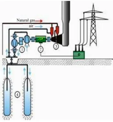
Compressed air energy storage system (CAES) is a hy- brid technology of long term power storage and genera- tion. A CAES plant mainly consists of 1) compressor train; 2) motor-generator unit; 3) gas turbine; and 4) un- derground compressed air storage tank (see Figure 9).
[image:6.595.340.502.600.724.2]During low-cost off-peak load periods, air is compressed and stored in large underground salt caverns [68]. Upon demand, the process is reversed; the compressed air is returned to the surface; this air is used to burn natural gas in the combustion chambers. The resulting combustion gas is then expanded in the two-stage gas turbine to spin
Figure 9. Major components of a CAES plant.
the generator and produce electricity.
CAES can be placed near consumers and in large, small, and micro scale smart power networks. As in many countries, the potentials of installing new hydro- storage plants with pumping facilities are limited and many other energy storage devices are far from being economic, CAES may be an attractive investment op- portunity for such purposes. The first such plant was built in Huntorf, Germany, in 1978 with a capacity of 290 MW [68]. In 1991, the first U.S. CAES facility was built in McIntosh, Alabama, by the Alabama Electric Cooperative and EPRI, and has a capacity rating of 110 MW [69]. Liu et al. [70] has proposed a novel hybrid- fuel CAES system for China. The design is based on us- ing standard, industry proven equipment components to deliver a reliable and economic compressed air energy cycle. The resulting CAES plant consists of 410 MW ge- neration, 205 MW of compression, and 2050 MW of sto- rage.
In the past few years, research has been conducted to improve the efficiency of the turbines and heat transfer mechanisms used to pump and retrieve compressed air [71-73]. In an adiabatic CAES, the air’s heat energy is stored separately and recovered before the compressed air is expanded in an air turbine. Such plants are cur- rently under development and promise higher efficien- cies and zero direct CO2-emissions [71].
4.6. Pumped Hydroelectric Storage
Pumped hydroelectric storage (PHS) is the oldest kind of large-scale energy storage technology [74]. Since 1904, they are in active operation and new ones are still being built because of their operational flexibility and ability to provide rapid response to changes in system loading or spot price of electricity.
Conventional pumped hydroelectric storage consists of two large reservoirs, one is located at base level and the other is situated at a different elevation. Water is pumped to the upper reservoir where it can be stored as potential energy. Upon demand, water is released back into the lower reservoir, passing through hydraulic turbines which generate electrical power as high as 1000 MW. Pumped hydroelectric storage has huge energy and power capac- ity. Recently [75-77] examined the impact of pumped storage units together with large renewable penetration. They focused on reducing system operating costs and maximizing usage of renewable energy based on unit commitments and dispatches. Currently, efforts aimed at increasing the use of pumped hydro storage are focused on the development of underground facilities. Modern pumped storage plants are often designed to have fast start, load ramping and unloading capabilities. They can respond to load changes within seconds.
4.7. Hybrid Energy Storage System
The selection of the energy storage system for a particu- lar application in power grid sometimes depends on a suitable combination of the power and energy ratings, energy, power density, cost, weight, volume, and operat- ing temperature etc of ESSs. These requirements may not be achievable from a single energy storage source. To implement such optimal applications, hybrid energy stor- age devices (HESDs) have been proposed. In a HESD, two or more different energy storage systems with com- plementary characteristics can be combined together elec- tronically. For future grid application proposed HESDs are listed next, with the energy-supplying device listed first, followed by the power-supplying device:
1) battery and ultracapacitor [78-81]; 2) battery and flywheels [82];
3) CAES and battery or ultracapacitor [83]; 4) battery and SMES [84].
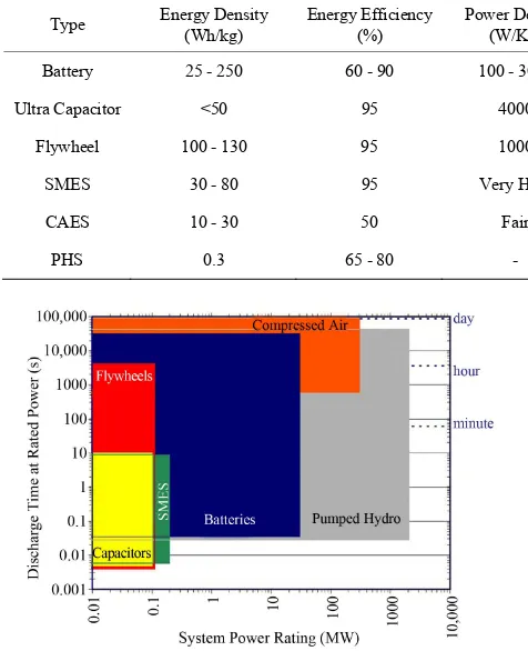
Figure 10 demonstrates the relationship between po-
wer operational range and discharge time at rated power for various energy storage systems such as battery, ultra- capacitors, flywheel, SMES, CAES, and pumped hydro.
Table 2 summarizes the characteristic parameters of dif-
ferent energy storage technologies [30,42-44,59,83].
5. Concluding Remarks
Table 2. Comparison of various energy storage systems.
Type Energy Density (Wh/kg) Energy Efficiency (%) Power Density (W/Kg) Life Time (Cycles) Self Discharge (%/Month) Environmental Effect
Battery 25 - 250 60 - 90 100 - 3000 150 - 3000 3 - 30 Toxic
Ultra Capacitor <50 95 4000 10 k - 100 k High Benign
Flywheel 100 - 130 95 1000 >125,000 High Benign
SMES 30 - 80 95 Very High - Negligible Benign
CAES 10 - 30 50 Fair 40 Years Negligible Benign
[image:8.595.55.293.104.397.2]PHS 0.3 65 - 80 - 75 Years Negligible Benign
Figure 10. The relationship between power rating and dis- charge time for different storage technologies.
grids in the future will take advantage of storage to deal with more dynamic loads and sources. As market rules are adjusted to take advantage of the benefits of bulk and distributed storage devices, the overall capabilities and reliability of more complex electricity networks should continue to improve as fully integrated smart grids.
REFERENCES
[1] K. Moslehi and R. Kumar, “A Reliability Perspective of the Smart Grid,” IEEE Transactions on Smart Grid, Vol. 1, No. 1, 2010, pp. 57-64.
doi:10.1109/TSG.2010.2046346
[2] P. Zhang, F. Li and N. Bhatt, “Next-Generation Monitor- ing, Analysis, and Control for the Future Smart Control Center,” IEEE Transactions on Smart Grid, Vol. 1, No. 2, 2010, pp. 186-192. doi:10.1109/TSG.2010.2053855 [3] S. M. Amin and B. F. Wollenberg, “Toward a Smart Grid:
Power Delivery for the 21st Century,” IEEE Power En- ergy Magazine, Vol. 3, No. 5, 2005, pp. 34-41.
doi:10.1109/MPAE.2005.1507024
[4] International Energy Agency, “Technology Roadmap: Smart Grids,” 2011.
http://www.iea.org/publications/freepublications/publicati on/name,3972,en.html
[5] US Department of Energy, “How the Smart Grid Pro-
motes a Greener Future,” 2010.
http://energy.gov/oe/downloads/how-smart-grid-promotes-greener-future
[6] H. Gharavi and R. Ghafurian, “Smart Grid: The Electric Energy System of the Future,” IEEE Proceedings, Vol. 99, No. 6, 2011, pp. 917-921.
[7] J. Xia and Y. Wang, “Secure Key Distribution for the Smart Grid,” IEEE Transactions on Smart Grid, Vol. 3, No. 3, 2012, pp. 1437-1443.
[8] A. Molderink, V. Bakker, M. G. C. Bosman, J. L. Hurink and G. J. M. Smit, “Management and Control of Domes- tic Smart Grid Technology,” IEEE Transactions on Smart Grid, Vol. 1, No. 2, 2010, pp. 109-119.
doi:10.1109/TSG.2010.2055904
[9] A. Bose, “Smart Transmission Grid Applications and Their Supporting Infrastructure,” IEEE Transactions on Smart Grid, Vol. 1, No. 1, 2010, pp. 11-19.
doi:10.1109/TSG.2010.2044899
[10] B. P. Roberts and C. Sandberg, “The Role of Energy Sto- rage in Development of Smart Grids,” IEEE Proceedings, Vol. 99, No. 6, 2011, pp. 1139-1144.
doi:10.1109/JPROC.2011.2116752
[11] M. S. Whittingham, “History, Evolution, and Future Sta- tus of Energy Storage,” IEEE Proceedings, Vol. 100, No. , 2012, pp. 1518-1534.
[12] G. D. Rodriguez, “A Utility Perspective of the Role of Energy Storage in the Smart Grid,” 2010 IEEE Power and Energy Society General Meeting,Minneapolis, 25-29 July 2010, pp. 1-2. doi:10.1109/PES.2010.5589870 [13] US Department of Energy, “Energy Storage—A Key
Enabler of the Smart Grid,” 2009.
http://www.netl.doe.gov/smartgrid/refshelf.html#White% 20Papers
[14] US Department of Energy, “The Smart Grid: An Intro- duction, 2008.
http://energy.gov/oe/downloads/smart-grid-introduction-0 [15] F. Li, W. Qiao, H. Sun, H. Wan, J. Wang, et al., “Smart
Transmission Grid: Vision and Framework,” IEEE Tran- sactions on Smart Grid, Vol. 1, No. 2, 2010, pp. 168-177. doi:10.1109/TSG.2010.2053726
[17] S. S. S. R. Depuru, L. Wang, V. Devabhaktuni and N. Gudi, “Smart Meters for Power Grid—Challenges, Issues, Advantages and Status,” 2011 IEEE/PES Power Systems Conference and Exposition (PSCE),Phoenix, 20-23 March 2011, pp. 1-7. doi:10.1109/PSCE.2011.5772451
[18] D. Rua, D. Issicaba, F. J. Soares, P. M. R. Almeida, R. J. Rei and J. A. P. Lopes, “Advanced Metering Infrastruc- ture Functionalities for Electric Mobility,” 2010 IEEE PES Innovative Smart Grid Technologies Conference Eu- rope (ISGT Europe),Porto, 11-13 October 2010, pp. 1-7. [19] H. Suleiman, K. A. Ahmed, N. Zafar, et al., “Inter-Do- main Analysis of Smart Grid Domain Dependencies Us- ing Domain-Link Matrices,” IEEE Transactions on Smart Grid, Vol. 3, No. 2, 2012, pp. 692-709.
doi:10.1109/TSG.2011.2176151
[20] Microsoft Power and Utilities, “Smart Energy Reference Architecture (SERA),” 2009.
[21] A. P. S. Meliopoulos, G. Cokkinides, R. Huang, E. Faran- tatos, S. Choi, et al., “Smart Grid Technologies for Auto- nomous Operation and Control,” IEEE Transactions on Smart Grid, Vol. 2, No. 1, 2011, pp. 1-10.
doi:10.1109/TSG.2010.2091656
[22] A. Ipakchi and F. Albuyeh, “Grid of the Future,” IEEE Power Energy Magazine, Vol. 7, No. 2, 2009, pp. 52-62. doi:10.1109/MPE.2008.931384
[23] R. A. F. Currie, G. W. Ault, C. E. T. Foote, N. M. Mc- Neill, et al., “Smarter Ways to Provide Grid Connections for Renewable Generators,” IEEE PES General Meeting, Minneapolis, 25-29 July 2010, pp. 1-6.
[24] Q. Pang, H. Gao and M. Xiang, “Design of Intelligent Terminal Unit for Smart Distribution Grid,” Proceedings of the IEEE China International Conference on Electric- ity Distribution (CICED), Nanjing, 13-16 September 2010, pp. 1-6.
[25] F. Rahimi and A. Ipakchi, “Demand Response as a Mar- ket Resource under the Smart Grid Paradigm,” IEEE Tran- sactions on Smart Grid, Vol. 1, No. 1, 2010, pp. 82-88. doi:10.1109/TSG.2010.2045906
[26] E. Santacana, G. Rackliffe, L. Tang and X. Feng, “Gett- ing Smart,” IEEE Power Energy Magazine, Vol. 8, No. 2, 2010, pp. 41-48. doi:10.1109/MPE.2009.935557
[27] K. C. Divya and J. Østergaard, “Battery Energy Storage Technology for Power Systems: An Overview,” Electric Power System Research, Vol. 79, No. 4, 2009, pp. 511- 520. doi:10.1016/j.epsr.2008.09.017
[28] M. M. Chowdhury, M. E. Haque, M. Aktarujjaman, M. Negnevitsky and A. Gargoom, “Grid Integration Impacts and Energy Storage Systems for Wind Energy Applica- tions—A Review,” Proceedings of the IEEE PES General Meeting,San Diego, 24-29 July 2011, pp. 1-8.
[29] S. C. Smith, P. K. Sen and B. Kroposki, “Advancement of Energy Storage Devices and Applications in Electrical Power System,” IEEE PES General Meeting, Pittsburgh, 20-24 July 2008, pp. 1-8.
[30] S. Vazquez, S. M. Lukic, E. Galvan, L. G. Franquelo, et al., “Energy Storage Systems for Transport and Grid Ap- plications,” IEEE Transactions on Industrial Electronics, Vol. 57, No. 12, 2010, pp. 3881-3895.
doi:10.1109/TIE.2010.2076414
[31] A. A. Thatte and L. Xie, “Towards a Unified Operational Value Index of Energy Storage in Smart Grid Environ- ment,” IEEE Transactions on Smart Grid, Vol. 3, No.3, 2012, pp. 1418-1426.
[32] W. Kempton and J. Tomic, “Vehicle-to-Grid Power Fun- damentals: Calculating Capacity and Net Revenue,” Jour- nal of Power Sources, Vol. 144, No. 1, 2005, pp. 268-279. doi:10.1016/j.jpowsour.2004.12.025
[33] A. Bracale, P. Caramia and D. Proto, “Optimal Operation of Smart Grids Including Distributed Generation Units and Plug in Vehicles,” International Conference on Re- newable Energies Power Quality (ICREPQ’11), Las Pal- mas de Gran Canaria, 13-15 April 2011, pp. 553-558. [34] M. M. Biswas, K. K. Das, I. A. Baqee, M. A. H. Sadi and
H. M. S. Forhad, “Prospects of Renewable Energy and Energy Storage Systems in Bangladesh and Developing Economics,” Global Journal of Researches in Engineer- ing (GJRE), Vol. 11, No. 5, 2011, pp. 23-31.
[35] Y. M. Cheng, Y. C. Liu, S. C. Hung and C. S. Cheng, “Multi-Input Inverter for Grid-Connected Hybrid PV/ Wind Power System,” IEEE Transactions on Power Elec- tronics, Vol. 22, No. 3, 2007, pp. 1070-1076.
doi:10.1109/TPEL.2007.897117
[36] J. M. Carrasco, L. G. Franquelo, J. T. Bialasiewicz, E. Galvan, R. C. P. Guisado, et al., “Power Electronic Sys- tems for the Grid Integration of Renewable Energy Sources: A Survey,” IEEE Transactions on Power Elec- tronics, Vol. 53, No 4, 2006, pp. 1002-1016.
doi:10.1109/TIE.2006.878356
[37] R. B. Schainker, “Executive Overview: Energy Storage Options for a Sustainable Energy Future,” IEEE PES General Meeting, Palo Alto, June 2004, Vol. 2, pp. 2309- 2314.
[38] C. A. Hill, M. C. Such, D. Chen, J. Gonzalez, et al., “Bat- tery Energy Storage for Enabling Integration of Distrib- uted Solar Power Generation,” IEEE Transactions on Smart Grid, Vol. 3, No. 2, 2012, pp. 850-857.
doi:10.1109/TSG.2012.2190113
[39] J. McDowall, “Nickel-Cadmium Batteries for Energy Sto- rage Applications,” The 14th Annual Battery Conference on Applications and Advances, Long Beach, 12-15 Janu- ary 1999, pp. 303-308.
[40] J. P. Barton and D. G. Infield, “Energy Storage and Its Use with Intermittent Renewable Energy,” IEEE Trans- actions on Energy Conversion, Vol. 19, No. 2, 2004, pp. 441-448. doi:10.1109/TEC.2003.822305
[41] P. C. Symons, “Opportunities for Energy Storage in Stressed Electrical Supply Systems,” IEEE PES Summer Meeting, Vancouver, July 2001, Vol. 1, pp. 448-449.
[42] D. Y. Goswami and F. Kreith, “Energy Conversion,” CRC Press, Boca Raton, 2007.
doi:10.1201/9781420044324
[44] B. R. Williams and T. Hennessy, “Energy Oasis [Vana- dium Redox Battery System in Power Distribution Ap- plication],” IEEE Power Engineer, Vol. 19, No. 1, 2005, pp. 28-31. doi:10.1049/pe:20050105
[45] Nesscap Ultracapacitors Products, “(EDLC) Electric Dou- ble-Layer Capacitor,” 2012.
http://www.nesscap.com/product/edlc_large1.jsp
[46] D. Halber, “Researchers Fired Up over New Battery,” MIT Tech Talk, Vol. 50, No. 16, 2006, pp. 1-5.
http://web.mit.edu/newsoffice/2006/batteries-0208.html [47] Maxwell Technologies, “An Overview of Ultracapacitor
Technology,” 2012.
http://www.maxwell.com/ultracapacitors/
[48] R. D. Weir and C. W. Nelson, “Utilization of Poly (Eth- ylene Terephthalate) Plastic and Composition-Modified Barium Titanate Powders in a Matrix that Allows Polari- zation and the Use of Integrated-Circuit Technologies for the Production of Lightweight Ultrahigh Electrical En- ergy Storage Units (EESU),” US Patent No. 7466536, 2008.
[49] H. Pan, J. Li and Y. P. Feng, “Carbon Nanotubes for Su- percapacitor,” Nanoscale Research Letters,Vol. 5, No. 3, 2010, pp. 654-668. doi:10.1007/s11671-009-9508-2 [50] H. Zhang, G. P. Cao, Y. S. Yang and Z. N. Gu, “Com-
parison between Electrochemical Properties of Aligned Carbon Nanotube Array and Entangled Carbon Nanotube Electrodes,” Journal of Electrochemical Society,Vol. 155, No. 2, 2008, pp. 19-22. doi:10.1149/1.2811864
[51] R. Hebner, J. Beno and A. Walls, “Flywheel Batteries Come Around Again,” IEEE Spectrum, Vol. 39, No. 4, 2002, pp. 46-51. doi:10.1109/6.9 93788
[52] G. Cimuca, C. Saudemont, B. Robyns and M. M. Radu- lescu, “Control and Performance Evaluation of a Fly- wheel Energy Storage System Associated to a Variable- Speed Wind Generator,” IEEE Transactions on Industrial Electronics, Vol. 53, No. 4, 2006, pp. 1074-1085. doi:10.1109/TIE.2006.878326
[53] G. Cimuca, S. Breban, M. Radulescu, C. Saudemont, et al., “Design and Control Strategies of an Induction-Ma- chine-Based Flywheel Energy Storage System Associated to a Variable-Speed Wind Generator,” IEEE Transactions on Energy Conversion, Vol. 25, No. 2, 2010, pp. 526-534. doi:10.1109/TEC.2010.2045925
[54] M. Subkhan and M. Komori, “New Concept for Flywheel Energy Storage System Using SMB and PMB,” IEEE Transactions on Applied Superconductivity, Vol. 21, No. 3, 2011, pp. 1485-1488.
doi:10.1109/TASC.2010.2098470
[55] J. Lee, S. Jeong, Y. H. Han and B. J. Park, “Concept of Cold Energy Storage for Superconducting Flywheel En- ergy Storage System,” IEEE Transactions on Applied Superconductivity, Vol. 21, No. 3, 2011, pp. 2221-2224. doi:10.1109/TASC.2010.2094177
[56] T. Ichihara, K. Matsunaga, M. Kita, I. Hirabayashi, et al., “Application of Superconducting Magnetic Bearings to a 10 kWh-Class Flywheel Energy Storage System,” IEEE Transactions on Applied Superconductivity, Vol. 15, No. 2, 2005, pp. 2245-2248. doi:10.1109/TASC.2005.849622
[57] N. Hamsic, A. Schmelter, A. Mohd, et al., “Stabilising the Grid Voltage and Frequency in Isolated Power Sys- tems Using a Flywheel Energy Storage System,” The Great Wall World Renewable Energy Forum, Beijing, 23-27 October 2006, pp. 1-6.
[58] E. Ortjohann, N. Hamsic, A. Schmelter, et al., “Increasing Renewable Energy Penetration in Isolated Grids Using a Flywheel Energy Storage System,” International Confe- rence on Power Engineering, Energy and Electrical Drives, Setubal, 12-14 April 2007, pp. 195-200.
[59] M. Lazarewicz and J. Judson, “Performance of First 20 MW Commercial Flywheel Frequency Regulation Plant,” ESA 2011 Annual Meeting, Beacon Power Corporation, San Jose, June 2011.
[60] D. Sutanto and K. W. E. Cheng, “Superconducting Mag- netic Energy Storage Systems for Power System Applica- tions,” International Conference on Applied Superconduc- tivity and Electromagnetic Devices,Chengdu, 25-27 Sep-tember 2009, pp. 377-380.
[61] IEEE Task Force and T&D Committee, “Detailed Mode- ling of Superconducting Magnetic Energy Storage (SMES) System,” IEEE Transactions on Power Delivery, Vol. 21, No. 2, 2006, pp. 699-710.
doi:10.1109/TPWRD.2005.864075
[62] V. Karasik, K. Dixon, C. Weber, B. Batchelder, G. Camp- bell and P. Ribeiro, “SMES for Power Utility Applica- tions: A Review of Technical and Cost Considerations,” IEEE Transactions on Applied Superconductivity, Vol. 9, No. 2, 1999, pp. 541-546. doi:10.1109/77.783354 [63] M. G. Molina and P. E. Mercado, “Comparative Evalua-
tion of Performance of a STATCOM and SSSC both In- tegrated with SMES for Controlling the Power System Frequency,” 2004 IEEE/PES Transmission and Distribu- tion Conference and Exposition: Latin America, São Paulo, 8-11 November 2004, pp. 535-541.
[64] M. G. Molina and P. E. Mercado, “New Energy Storage Devices for Applications on Frequency Control of the Power System Using FACTS Controllers,” Proceedings of X ERLAC, Iguazú, 18-22 May 2003, pp. 1-6.
[65] Y. Tatusuta, S. Koso, H. Abe, M. Urata, H. Ohsaki, et al., “Development of SMES for Power System Control,” IEEE Transactions on Applied Superconductivity, Vol. 14, No. 2, 2004, pp. 693-698.
doi:10.1109/TASC.2004.830033
[66] S. Nomura, T. Shintomi, S. Akita, T. Nitta, R. Shimada and S. Meguro, “Technical and Cost Evaluation on SMES for Electric Power Compensation,” IEEE Transactions on Applied Superconductivity, Vol. 20, No. 3, 2010, pp. 1373- 1378. doi:10.1109/TASC.2009.2039745
[67] Q. Li, “Status and Future Prospect of SMES for Grid Applications,” Advanced Microgrid Concepts and Tech- nologies Workshops, Brookhaven National Laboratory, Washington DC, 2012.
[68] F. Crotogino, K. U. Mohmeyer and R. Scharf, “Huntorf CAES: More than 20 Years of Successful Operation,” The Solution Mining Research Institute Spring Meeting, Or- lando, 23-25 April 2001.
ergy Storage: 1994,” EPRI Brochure BR-102936. [70] W. Liu, Y. Yang, W. Zhang, G. Xu and Y. Wu, “A Novel
Hybrid-Fuel Compressed Air Energy Storage System for China’s Situation,” Proceedings of the International Con- ference of Efficiency, Cost, Optimization, Simulation En- vironmental Impact Energy Systems, Perugia, 26-29 June 2012, pp. 1-16.
[71] C. Bullough, C. Gatzen, C. Jakiel, M. Koller, et al., “Ad- vanced Adiabatic Compressed Air Energy Storage for the Integration of Wind Energy,” Proceedings of European Wind Energy Conference, EWEC,London, 22-25 Novem- ber 2004, pp. 1-8.
[72] C. Linnemann and M. W. Coney, “The Isoengine: Reali- zation of a High-Efficiency Power Cycle Based on Iso- thermal Compression,” International Journal of Energy Technology and Policy, Vol. 3, No. 1-2, 2005, pp. 66-84. doi:10.1504/IJETP.2005.006740
[73] Ridge Energy Storage & Grid Services L. P., “The Eco- nomic Impact of CAES on Wind in TX, OK and NM,” Texas State Energy Conservation Office, Austin, 2005. [74] P. Breeze, “Power Generation Technologies,” Elsevier,
Boston, 2005.
[75] P. Brown, J. Lopes and M. Matos, “Optimization of Pumped Storage Capacity in an Isolated Power System with Large Renewable Penetration,” IEEE Transactions on Power Systems, Vol. 23, No. 2, 2008, pp. 523-531. doi:10.1109/TPWRS.2008.919419
[76] J. G. Gonzalez, R. D. L. Muela, L. Santos and A. Gonza- lez, “Stochastic Joint Optimization of Wind Generation and Pumped-Storage Units in an Electricity Market,” IEEE Transactions on Power Systems, Vol. 23, No. 2, 2008, pp. 460-468. doi:10.1109/TPWRS.2008.919430 [77] A. Tuohy and M. O’Malley, “Impact of Pumped Storage
on Power Systems with Increasing Wind Penetration,” IEEE Power & Energy Society General Meeting, Calgary,
26-30 July 2009, pp. 1-8.
[78] W. Henson, “Optimal Battery/Ultracapacitor Storage Com- bination,” Journal of Power Sources, Vol. 179, No. 1, 2008, pp. 417-423. doi:10.1016/j.jpowsour.2007.12.083 [79] H. Yoo, S. K. Sul, Y. Park and J. Jeong, “System Integra-
tion and Power Flow Management for a Series Hybrid Electric Vehicle Using Super-Capacitors and Batteries,” IEEE Transactions on Applied Superconductivity, Vol. 44, No. 1, 2008, pp. 108-114. doi:10.1109/TIA.2007.912749 [80] L. Shuai, K. A. Corzine and M. Ferdowsi, “A New Bat-
tery/Ultracapacitor Energy Storage System Design and Its Motor Drive Integration for Hybrid Electric Vehicles,” IEEE Transactions on Vehicular Technology, Vol. 56, No. 4, 2007, pp. 1516-1523. doi:10.1109/TVT.2007.896971 [81] M. B. Camara, H. Gualous, F. Gustin and A. Berthon,
“Design and New Control of DC/DC Converters to Share Energy between Supercapacitors and Batteries in Hybrid Vehicles,” IEEE Transactions on Vehicular Technology, Vol. 57, No. 5, 2008, pp. 2721-2735.
doi:10.1109/TVT.2008.915491
[82] O. Briat, J. M. Vinassa, W. Lajnef, S. Azzopardi and E. Woirgard, “Principle, Design and Experimental Valida- tion of a Flywheel-Battery Hybrid Source for Heavy-Duty Electric Vehicles,” IET Electric Power Applications, Vol. 1, No. 5, 2007, pp. 665-674.
doi:10.1049/iet-epa:20060458
[83] S. Lemofouet and A. Rufer, “A Hybrid Energy Storage System Based on Compressed Air and Supercapacitors with Maximum Efficiency Point Tracking (MEPT),” IEEE Transactions on Industrial Electronics, Vol. 53, No. 4, 2006, pp. 1105-1115. doi:10.1109/TIE.2006.878323 [84] T. Ise, M. Kita and A. Taguchi, “A Hybrid Energy Stor-