970
©IJRASET: All Rights are Reserved
Effect of Cutting Forces in Single Point HSS Tool
while Turning
Arun M S1, Ananthakrishnan T S2, Balagopal P B3, Georgy S Samuel4, S. Sarath5
1, 2, 3, 4,
Student, B-Tech Mechanical Engineering, St Thomas College of Engg. And Technology, Chengannur 5
Asst Professor, B-Tech Mechanical Engineering, St Thomas College of Engg. And Technology, Chengannur
Abstract: High speed steel material tools are frequently used to machine products which finds frequent applications in machining process mainly by turning operation. Hence it is necessary to know various stress levels and possibilities of failures during machining process. A method is proposed with finite element analysis to determine vulnerable regions of the HSS tool by determining its stress contours through its geometry. Cutting forces must be determined by strain gauge dynamometer and also feed rate ,spindle speed, depth of cut and cutting velocities are used to determined experimentally for the purpose. With various influential parameters, finite element analysis is done with the help of solid works and maximum shear stresses are calculated to determine the weak regions.
Keywords: Turning, Cutting forces, Von misses stress, FEM, SOLIDWORKS
I. INTRODUCTION
Machining is a regular manufacturing approach where material eliminated from a part employing a tool with a small, hard point. In order to fabricate a part promptly, a high cutting speed preferred. This higher velocity may cause faster degradation of the tool point, which may cause tool to change regularly. There are many models amd theories pertaining to calculate this period. It is very necessary to predict the tool wear according to input machining parameters. It is desired to determine the stress on turning tool materials so that the particular tool must use for a threshold operation. Surface quality and tool wear in various turning treatments were specified by Pavel et al. [1].Dawson and Kurfess [2], mentioned experimental and theoretical roughness values for high feed values. The impact of soothing on flank wear was analyzed by Zhao et al. [3]. Chang-Xue et al. [4] described the numerous constraints influencing surface roughness of the turned surface. Chou and Evans [5] presented the properties of different work pieces and cutting conditions. The optimal tool life period of tools was analyzed by Negishi et al. [6]. The method of orthogonal metal cutting is examined by Shih [7] considering the finite element method under plane strain circumstances. Baker and Rouch[8] shows finite element modelling of a cutting tool just before its fracture and able to predict the failure conditions. By this analysis and study we develop a method to study stresses occurring on tool tip while machining. It also offers to determine shear stress at weak regions of tool, life of the cutting tool local stresses and effects of cutting forces to that spindle speed, feed rate, depth of cut and cutting velocity.
II. EXPERIMENTALSETUP
The experimental set-up was prepared by using cutting parameters and test conditions that are advised by the tool manufacturer. In order to measure main cutting force Fc, feed force Ff, and thrust force Ft, a 2D turning dynamometer was used. Workpiece material
is taken to be of mild steel bar of 50 mm. in diameter. After taking the readings of the cutting forces the diameter decreases and noted accordingly for variable cutting velocity. The tool with geometry 6-8-10-10-20-45-0.6 is selected.
The cutting tests were carried in single-point turning operations. Three process parameters namely feed rate, cutting speed and depth of cut were considered to perform turning operations keeping all other parameters constant. The radial cutting force (Fy) is not detected by the dynamometer as it a 2D strain gauge dynamometer. The radial cutting force is dependent on tangential cutting force and it is calculated by the formula below which is mentioned by A.K. Dutta[9], Fy = 0.14 x Fz
1) Fy1 = 0.14×58.3=8.16N
2) Fy2 =0.14×69.04=9.66N
3) Fy3=0.14×82.4=11.536N
4) Fy4=0.14×312.2=43.70N
971
©IJRASET: All Rights are Reserved
III.FINITEELEMENTANALYSIS(FEA)
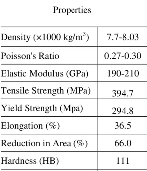
[image:2.612.156.470.113.273.2]The solid works 13 simulation (SWS13) is used to analyze stresses in turning process. It is a computer-based numerical technique which makes the structure under analysis in to finite elements and calculates its strength individually. So the results will be more accurate. It can be used to calculate the effects on tools by the application of stresses which causes the phenomena like deflection, stress, vibration, buckling behavior etc. A cutting tool is usually subjected to multi-axial stresses in a cutting process such that each face may be subjected to the total force. Relatively lower tensile strength of modern cutting tools (i.e., carbide tools) makes them prone to brittle failure due to chipping and fracture. Premature failure often results due to improper selection of cutting parameters, which causes excessive stress on the cutting edge. Generally when the induced stress in a cutting tool reaches a critical value, tool failure will occur. In cutting process, the surface is influenced by changes in tool geometry, chip flow, temperature generation, heat flow and tool wears. The understanding of these interactions during the cutting process is done by static and dynamic analyses with the help of finite element analysis software, called SOLIDWORKS. . Table II showing the material properties of HSS, the density, poissons ratio, shear modulus, tensile strength, yield strength, hardness is mentioned.
TABLE II
Material Properties Of Hss Tool
[image:2.612.237.385.482.654.2]972
[image:3.612.183.443.81.194.2]©IJRASET: All Rights are Reserved
Fig.1 load and fixtures applied
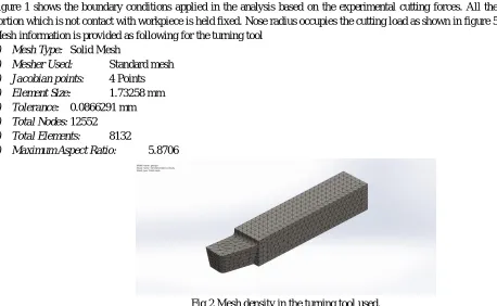
Figure 1 shows the boundary conditions applied in the analysis based on the experimental cutting forces. All the area except the portion which is not contact with workpiece is held fixed. Nose radius occupies the cutting load as shown in figure 5.1.
Mesh information is provided as following for the turning tool
1) Mesh Type: Solid Mesh
2) Mesher Used: Standard mesh
3) Jacobian points: 4 Points
4) Element Size: 1.73258 mm
5) Tolerance: 0.0866291 mm
6) Total Nodes: 12552
7) Total Elements: 8132
[image:3.612.48.506.221.503.2]8) Maximum Aspect Ratio: 5.8706
Fig 2 Mesh density in the turning tool used.
Figure 2 shows the mesh density in the turning tool used. A static analysis calculates the effects of steady loading conditions on a structure, while ignoring inertia and damping effects. In a static analysis a rigidity matrix is calculated for each element according to the given specifications. These matrices are aggregated and the rigidity matrix of the system is generated. The solution is the zero displacements of the nodes that are fixed to the tool holder. In this research, free meshes are used for the FEM of the cutting tool. Experimental data shows that if the calculated stress of the cutting tool is much above the material yield strength, the tool fractures under the critical forces. Since these forces are the measured forces when the tool breaks, the result shows that the metal cutting process predicted by the finite elements model agreed well with experimental results.
IV.RESULTSANDDISCUSSION
973
©IJRASET: All Rights are Reserved
The finite element and numerical analysis results of equivalent von misses stress are carried out and it’s approximately equal to the numerical breaking stress. The FEA analysis of single point cutting tool showing the stress analysis of the single point cutting tool with 2 different feeds and 3 different cut from the finite element analysis maximum breaking stress is 45.819 MPa (0.50mm gap and 290 rpm).
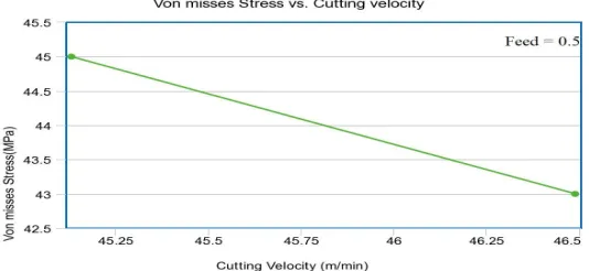
The following graphs show how the three cutting forces and vonmises maximum stress are related with the cutting velocity when the other parameters like feed rates, spindle speeds and depth of cuts are varied.
Fig.3 Graph showing relation between cutting force v/s cutting velocity
974
©IJRASET: All Rights are Reserved
[image:5.612.180.447.81.204.2]Fig 5 Graph showing relation between cutting velocity v/s max Von mises stress
Fig.6 Graph showing relation between cutting force v/s cutting velocity
V. CONCLUSION
The goal of this work is to present a method in order to determine tool forces and temperatures for use in finite element simulations of metal cutting processes. From the experimental set up, it is clearly observed that as depth of cut increases, the temperature generated in the tool at the tool tip also increases. It is also observed that, as the depth of cut increases, tool forces are also increases. It is main reason of tool failure. At this condition more heat is dissipated at the tool, due to which tool blunt. The values obtained from dynamometer were used to analyse stress in the tool. This analysis helps us to determine maximum stress occurred in tool with the set of input parameters. It is understood that if the maximum von Mises stress is higher than the yield strength 380 MPa (HSS) , it will result in tool wear and hence decreased tool life.
REFERENCES
[1] Pavel R et al (2001) Surface quality and tool wear in interrupted hard turning of 1137 steel shafts. Dana company, MIME Department, Advanced Technoplogy Resource Group, Technical Resource Park, Ottawa Lake, MI 49267, pp 1–6
[2] Dawson TG, Kurfees TR (2000) An investigation of tool wear and surface quality in hard turning. In: Transactions of 28th annual North American Manufacturing Research Institution of SME, University of Kentucky, Lexington, May 24–26, pp 215–220
[3] Zhao H, Barber GC, Zou Q (2002) A study of flank wear in orthogonal cutting with internal cooling. Wear 253:957–962
[4] Feng C-X (2001) An experimental study of the impact of turning parameters on surface roughness. In: Proceedings of the International Conference on Industrial Engineering Research, Bradley university, USA, Institute of Industrial Engineers, Norcross, GA, March 27–28, pp 1–11
[5] Chou Y, Evans CJ (1996) Microstructural effects in precision hard turning. ASME J Manuf 4:237–242
[6] Negishi H, Aoki A, Sata T (1980) Study of tool failure of carbide tools in interrupted cutting. Ann CIRP 29:57–60
[7] Shih, (2002) “A finite element study of the effect of friction in orthogonal metal cutting”, Finite Elements in Analysis and Design. Vol. 38, Issue 9, pp. 863 – 883.
[8] Baker and Rouch, (2005 )“Finite element analysis of cutting tools prior to fracture in hard turning operations”, Materials and design, Vol. 26, Issue 2, pp. 105-112.