University of Twente Department of Computer Science
Software Engineering Group
A Metamodeling Approach to
Incremental Model Changes
by
D.P.L. van der Meij
Master thesis
September 2008 to July 2009
Graduation committee:
I
A
BSTRACT
For the next step in raising the level of abstraction in software development, Kent (Kent, 2002) proposed an approach for Model Driven Engineering (MDE). With MDE it is possible to raise the level of abstraction such that decisions can be made regardless the implementation language. Business rules can be defined on a higher level so in fact programming happens at the level of models. Model transformations allow models to be turned into other models, for instance models of source code or other less abstract models.
This thesis is about model‐to‐model and model‐to‐text transformations. Usually model‐ to‐text aspects of thoughts are omitted because the text to be generated can also be modeled and thus a model‐to‐model transformation should be sufficient. Because in this thesis we focus on incremental model changes and also incremental changing the files in the file system, we explicitly studied model‐to‐text transformation approaches to keep model and text synchronized. In this thesis we use different terms for model‐to‐ model and model‐to‐text transformations. We use the term transformation when we are dealing with models as logical entities, we use the term generation when we are dealing with files as physical entities. For instance, in a model‐to‐text transformation the model will be transformed and the output will be generated files; the generation of files is due to the transformation of a model. We studied the possibilities to perform specific file generation and file modification based on a set of changes to a model.
II
A
BBREVIATIONS
Abbreviation Full description
ANTLR ANother Tool for Language Recognition
AST Abstract Syntax Tree
ATL Atlas Transformation Language CIM Computational Independent Model CRM Customer Relationship Management DSL Domain Specific Language
EBNF Extended Backus Naur Form EMF Eclipse Modeling Framework MDA Model Driven Architecture MDE Model Driven Engineering MOF Meta Object Facility
OCL Object Constraint Language
OMG Object Management Group
OO Object Oriented
PIM Platform Independent Model
PHP Hypertext Preprocessor
POC Proof of Concept
PSM Platform Specific Model QVT Query / View / Transformation
RFP Request for Proposal
UML Unified Modeling Language
III
L
IST OF FIGURES
Figure 1: Thesis outline ... 21
Figure 2: MDA transformation, PIM to PSM [21]... 24
Figure 3: MOF metamodeling stack [22]... 25
Figure 4: Comparison of the MOF stack to a program in C... 26
Figure 5: The basic model transformation pattern [18]... 27
Figure 6: Relationships between QVT metamodels [23] ... 28
Figure 7: Overview of ATL transformational approach [13] ... 29
Figure 8: Re‐transformation [11] ... 30
Figure 9: Live transformation [11] ... 31
Figure 10: Coarse‐grained transformation... 32
Figure 11: Fine‐grained transformation... 32
Figure 12: Transformation impact ... 38
Figure 13: Venn diagram of delta ... 39
Figure 14: Subset of delta that contains two additions ... 40
Figure 15: Subset of delta that contains a change... 41
Figure 16: Subset of delta that contains a deletion ... 41
Figure 17: Example source model... 55
Figure 18: Delta with an addition ... 55
Figure 19: Example resulting model after the transformation ... 56
Figure 20: Metamodel for models in the computer’s memory ... 61
Figure 21: Metamodel for entities in the file system... 62
Figure 23: Impact scale of model transformations ... 67
Figure 24: Entire model transformation map ... 67
Figure 25: Coarse‐grained model transformation map ... 68
Figure 26: Fine‐grained model transformation map... 69
Figure 27: Screenshot of the Novulo Architect... 73
Figure 28: Distribution of model revisions against number of nodes... 75
Figure 29: Total distribution of timings of 1000 experiments ... 80
Figure 30: Trimmed distribution of timings of 1000 experiments... 81
Figure 31: Benchmarks 1 to 5: nr of pages vs. time ... 82
Figure 32: Benchmarks 6 to 10: nr of fields vs. time... 83
Figure 33: Benchmarks 11 to 15: nr of pages vs. time... 84
Figure 34: Benchmarks 16 to 20: nr of fields vs. time... 85
Figure 35: Benchmarks 21 to 25: nr of pages vs. time ... 86
Figure 36: Benchmarks 26 to 30: nr of fields vs. time... 87
Figure 37: Class diagram of PoC... 99
IV
L
IST OF TABLES
Table 1: Properties of state of the art model transformation techniques... 50
Table 2: Additional mappings between metamodels ... 64
Table 3: Model‐to‐text approaches ... 67
Table 4: Properties of entities in the file system ... 78
Table 5: Addition benchmarks ... 81
Table 6: Changes benchmarks ... 84
V
L
IST OF LISTINGS
Listing 1: Example addition in QVT Relations... 42
Listing 2: Example change in QVT Relations ... 43
Listing 3: Example deletion in QVT Relations... 44
Listing 4: Example addition in QVT Operational Mappings... 46
Listing 5: Example change in QVT Operational Mappings ... 46
Listing 6: Example deletion in QVT Operational Mappings... 47
Listing 7: Example start of transformation ... 47
Listing 8: Example addition in ATL ... 49
Listing 9: Example change in ATL ... 49
Listing 10: Example deletion in ATL ... 50
Listing 11: Transforming additions and changes... 53
Listing 12: Transforming deletions... 53
Listing 13: Transforming additions, changes and deletions... 54
Listing 14: List with deltas... 100
Listing 15: Start of transformation... 101
Listing 16: Entire model transformation... 101
Listing 17: Coarse‐grained model transformation ... 102
Listing 18: Fine‐grained model transformation ... 102
VI
C
ONTENTS
I Abstract... 3
II Abbreviations... 5
III List of figures... 7
IV List of tables... 9
V List of listings... 11
VI Contents... 13
1 Introduction... 17
1.1 Introduction ... 17
1.2 Problem statement ... 18
1.3 Research questions ... 18
1.4 Approach... 19
1.5 Contributions ... 20
1.6 Thesis outline ... 20
2 Background... 23
2.1 Introduction ... 23
2.2 Model Driven Architecture ... 23
2.3 Metamodeling... 25
2.4 Model Transformations ... 27
2.5 Query / View / Transformation... 28
2.6 Atlas Transformation Language ... 29
2.7 Incremental model transformations... 30
2.9 Related work... 34
2.10 Conclusion... 35
3 Incremental model change approaches... 37
3.1 Introduction ... 37
3.2 Model transformations ... 38
3.3 State of the art model transformation techniques... 40
3.3.1 Example transformations... 40
3.3.2 QVT Relations... 41
3.3.3 QVT Operational Mappings... 45
3.3.4 ATL ... 48
3.3.5 Summary ... 50
3.4 Our proposal ... 51
3.4.1 Pseudo code fragments ... 52
3.4.2 Example transformation ... 55
3.5 Conclusion... 57
4 Different implementations of transformations... 59
4.1 Introduction ... 59
4.2 Model‐to‐model transformation ... 59
4.3 Model‐to‐text transformation ... 60
4.3.1 Entire model transformations... 60
4.3.2 Fine‐grained model transformation... 60
4.3.3 Coarse‐grained model transformation... 65
4.3.4 Summary ... 66
4.4 Conclusion... 69
5.1 Introduction ... 71
5.2 Novulo Architect ... 72
5.2.1 Metamodel / Domain Specific Language ... 73
5.2.2 Code generation... 74
5.3 Applications ... 74
5.3.1 Small CRM System... 75
5.3.2 Vacancy System... 76
5.3.3 Database Migration Tool... 76
5.4 Conclusion... 76
6 Benchmarking the implementations... 77
6.1 Introduction ... 77
6.2 Transformations... 77
6.2.1 Base models ... 78
6.2.2 Proof of concept... 78
6.2.3 General remarks... 79
6.2.4 Additions benchmarks ... 81
6.2.5 Changes benchmarks ... 83
6.2.6 Deletions benchmarks ... 85
6.3 Conclusion... 87
7 Conclusions... 89
7.1 Summary... 89
7.2 Research questions ... 90
7.3 Generalization... 91
7.4 Final conclusion... 93
1
I
NTRODUCTION
Since the beginning of the computer era people write software. This chapter gives a brief history to software development and introduces our problem statement. Furthermore we define our research questions and our approach to solve them. Next we give a summary of the contributions we made to cope with our problems and in the end the outline of the thesis is described.
1.1
I
NTRODUCTION
The first programming languages were very low‐level; instructions directly invoked the computer's hardware. One of the first languages was the assembly language. Assembly is a language that represented in a symbolic way the instructions supported by the hardware. Assembly programs have to be assembled before they can be executed. An assembler is a translator that translates source instructions (in symbolic language) into target instructions (in machine language), on a one‐to‐one basis (Salomon, 1993).
When programs became larger, the assembly language wasn't suitable anymore because it became too complex. New languages were invented to reduce the complexity on the level of programming language. Of course the software itself still was complex. Compilers were introduced to translate programs written in these more abstract languages into machine‐readable instructions. Besides the fact that new programming languages were more maintainable due to the fact that they were less complex to understand than their predecessors, programming languages also became more structured. General structures were invented to support all issues that could possibly be encountered (Dahl, Dijkstra, & Hoare, 1972). Over time more and more general structures were added (Moon, 1986) and even today new languages are still being invented.
This thesis is about model‐to‐model and model‐to‐text transformations. Usually model‐ to‐text aspects of thoughts are omitted because the text to be generated can also be modeled and thus a model‐to‐model transformation should be sufficient. Because in this thesis we focus on incremental model changes and also incremental changing the files in the file system, we explicitly studied model‐to‐text transformation approaches to keep model and text synchronized. In this thesis we use different terms for model‐to‐ model and model‐to‐text transformations. We use the term transformation when we are dealing with models as logical entities, we use the term generation when we are dealing with files as physical entities. For instance, in a model‐to‐text transformation the model will be transformed and the output will be generated files; the generation of files is due to the transformation of a model. We studied the possibilities to perform specific file generation and file modification based on a set of changes to a model.
1.2
P
ROBLEM STATEMENT
Suppose we use MDE to create models that represent complete applications. A transformation will for example generate code in a certain lower‐level programming language. The generated code will be stored as files in the file system. When the model is modified the affected code within these files should be synchronized. One naive solution to synchronize the files with the model is to execute the transformation on the modified model again. However, for large models this may be time consuming, especially when there is a long chain of model refinements and compositions (Kurtev, State of the Art of QVT: A Model Transformation Language Standard, 2008). Some files will not change after regeneration and thus the generation of those files is superfluous. Besides the fact that regenerating files that will not be changed is superfluous, it is also time consuming and thus inefficient. Consider a system consisting of 100 files, the smaller the amount of files to be changed, the less efficient the transformation will be. Incremental transformations seem to provide the solution for this problem, but current approaches only consider models and not physical representations in, for example, the file system. This comes also with a synchronization problem (unidirectional from model to files).
The general problem is that we want to synchronize a model with its representation in the file system. There are several possibilities and we are looking for the most efficient implementation.
1.3
R
ESEARCH QUESTIONS
changes that have to be done have to be collected in such a way that an incremental transformation based on those changes can be performed.
The main problem leads to the following research questions:
RQ1: Which files have to be synchronized when a model is changed and is it possible to only affect those files?
First we have to research if it is possible to only generate files that are affected by a change. If this fails, we can conclude that full regeneration of all files is the most efficient implementation.
RQ2: If specific file generation is possible, how to perform such a transformation?
When succeeding in finding a possibility of regenerating specific files, an algorithm to perform such a transformation remains to be researched.
RQ3: Which transformation method performs better for various source models and changes to the model?
Consider a large source model and a very small change. Intuitively an in‐place incremental transformation would be most efficient here. When considering a small source model and a very large change, intuitively a retransformation of all elements would be more efficient than performing an in‐place incremental transformation. We need to study the dependency between the time for performing the generation and the type of changes.
1.4
A
PPROACH
This thesis studies an approach to perform a transformation that only processes the files that are affected by the changes in the model. We have researched several implementations and benchmarked them against full regeneration of all files. It is also possible that some files are affected by all elements of the model. We suggest an approach to cope with those problems.
Per research question we defined an approach. Here we state how we researched our questions.
RQ1:
We first investigate the current model transformation techniques. We look for results that may support our goal to perform a so‐called incremental model change.
RQ2:
First we will discuss an algorithm how an incremental model change could be performed. We will also discuss several approaches to implement the proposed algorithm.
RQ3:
We will research the performance by benchmarking the proposed algorithm against the several implementation approaches and full regeneration of all files. As a reference to base the benchmark tests we used a case study of a commercial product.
1.5
C
ONTRIBUTIONS
The contribution of this thesis is a solution to the problem of incremental model changes in the file system. We proposed several implementations of the solution and with that we made a proof of concept (PoC) to demonstrate it. With the PoC we also benchmarked the several implementations of the solution. With this benchmarking results, we concluded that our approach is performing the way we expected it to be. With the results of this thesis, we hope incremental model changes, where the duration of the transformation is dependent on the size of the changes, will be supported by new or refined model transformation techniques.
1.6
T
HESIS OUTLINE
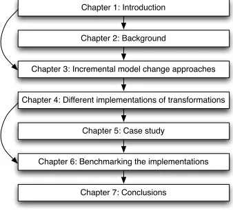
Figure 1: Thesis outline
Readers with experience in the field of MDA, metamodeling, model‐to‐model approaches, model‐to‐text approaches and incremental modeling techniques may skip chapter 2. Readers may also skip chapter 5 when not interested in the background information for the benchmarking of chapter 6.
Chapter 1: Introduction
Chapter 2: Background
Chapter 3: Incremental model change approaches
Chapter 4: Different implementations of transformations
Chapter 5: Case study
Chapter 6: Benchmarking the implementations
2
B
ACKGROUND
This chapter describes the background information about the subject of MDE and incremental model changes. We discuss model‐to‐model transformations and model‐to‐text transformations. In the end we also discuss state of the art MDE techniques and their capabilities of supporting incremental model changes.
2.1
I
NTRODUCTION
An approach for software development is model driven engineering (MDE). In MDE models are not only the basis of the software under development, but also the source code, in terms of traditional software development. Models are the leading artifacts in software development when using MDE. There are several implementations of MDE. This chapter gives more background information about the domain of MDE.
2.2
M
ODEL
D
RIVEN
A
RCHITECTURE
Figure 2: MDA transformation, PIM to PSM [21]
Figure 2 is intended to be suggestive and generic; the PIM and other information are combined into a PSM and there are many ways in which such a transformation may be done (Object Management Group (OMG), 2003). Whereas the PIM is defining the subject on an abstract level, the PSM is, next to defining the same subject as the PIM, also defining more details about the specific platform; more details about the environment. Next to the PIM to PSM transformation, MDA also describes the CIM to PIM transformation, were CIM is the Computational Independent Model. In general can be said, the lower the level of abstraction, the more details are needed for defining the subject. Most of those lower level details are more related to the external properties of the lower level abstraction than the subject itself. The higher the level of abstraction, the less details about the environment we need so we can be more focused on the subject itself.
Next to the PIM and PSM models, the transformations to transform a PIM to a PSM can also be modeled in MDA. The OMG proposed Query / View / Transformation (QVT) (Object Management Group (OMG), 2007) as a transformation standard. Because of the fact that transformations themselves aro also models, they can thus also be transformed into lower level transformations. In this way, the same transformation can be performed on each level of abstraction. Within QVT rules are described by the Object Constraint Language (OCL) (Object Management Group (OMG), 2005) also standardized by the OMG.
PSM
PIM
2.3
M
ETAMODELING
[image:25.612.208.406.314.619.2]
Another way of describing MDE in a more pragmatic way is as follows. Suppose we want to make a software application with a database to store information about customers. Then the first step is to make a definition of the domain of the application we want to make. When we completed our domain we created a metamodel for our application. Metamodels define the concepts of models to be made, they propose the structure of the models. In fact metamodels define a modeling language for models in a specific domain. Now we can make a model of our application within the just created metamodel. A metamodel defines the structure of an application and the model contains the specific details. When the model is completed, the application should be able to run in the real world.
Figure 3 shows the concepts of metamodeling which is called the MOF metamodeling stack. MOF is a language defined by OMG in which metamodels can be described (Object Management Group (OMG), 2002). MOF was first defined to facilitate all elements of the UML specification language.
Figure 3: MOF metamodeling stack [22]
Level M0 describes the real world objects. So when a program is to be executed, all objects that are within the computer memory are actual entities in the real world. Level M1 is a representation of the real world objects containing all details needed for the
Metametamodel level
Metamodel level
Model level
Real world
M3:
M2:
M1:
M0:
<< instance of >>
<< instance of >>
application to be executed in the real world. Level M2 describes the boundaries of the model in M1 and level M3 defines the concepts of metamodeling, which is self‐ descriptive. So in level M2 a domain specific language (DSL) is created whereas level M1 describes the application itself.
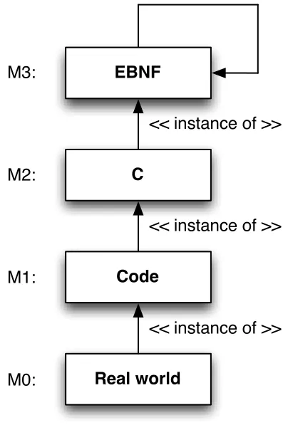
Figure 4 makes a comparison of MDE to the way a program written in C is constructed.
Figure 4: Comparison of the MOF stack to a program in C
As shown in Figure 4, the programming language is bound to an implementation in EBNF. The EBNF here restricts the programmer to only use the syntax that is specific to C. The actual code is written in the C language and the real world is the compiled application. When we look at this example, the concepts of MDE are not new but are used in many other (older) ways of software development.
Apart from performing vertical transformations in MDE, transforming models into lower level models, it is also possible to perform horizontal transformations. For example, when refining a model on level M1, a transformation can be invoked to transform the old model into the new model staying in level M1. Both models, the old and the refined model, are still instances of the M2 level. But if there were already transformations from the old model to level M0, then the model in M0 is not an instance of our new refined model. A new transformation has to be made to create a model in M0 which is an instance of the new refined model. This thesis focuses on transforming the model in M0
EBNF
C
Code
Real world M3:
M2:
M1:
M0:
<< instance of >>
<< instance of >>
which is an instance of the old model, to a model that is an instance of the new refined model, discarding the old model in M0. In other words, we synchronize the model in M0 to the new refined model in M1.
2.4
M
ODEL
T
RANSFORMATIONS
In MDE model transformations form the cornerstone in a software development process. Czarnecki and Helsen (Czarnecki & Helsen, 2003) made a classification of model transformation approaches which we wil briefly summarize here:
There are two major categories, namely model‐to‐model and model‐to‐text. In model‐ to‐text Czarnecki and Helsen define visitor‐based approaches and template‐based approaches. In template‐bases approaches templates contain already most of the text. There are some patterns of metadata that will be replaced by data from a model. In visitor‐based approaches the visitor design pattern of Gamma et al. (Gamma, Helm, Johnson, & Vlissides, 1995) is used to transform complete models into text using, for example, a text stream. In the model‐to‐model category Czarnecki and Helsen define direct‐manipulation approaches, relational approaches, graph‐transformation‐bases approaches, structure‐driven approaches, hybrid approaches and some other model‐to‐ model approaches. We are not discussing the model‐to‐model approaches here but this thesis focuses on the relational and the direct‐manipulation approaches. We refer to the paper of Czarnecki and Helsen for more information.
Kurtev and van den Berg (Kurtev & van den Berg, 2005) came up with a basic model transformation pattern as illustrated in Error! Reference source not found.5.
[image:27.612.118.507.453.659.2]Figure 5: The basic model transformation pattern [18]
Transformation Language
Transformation Specification
Metamodel A Metamodel B
Transformation Engine
Model A Model B
source target
written in
uses uses
instance of executed by instance of
On the left hand side of Error! Reference source not found.5 we see metamodel A, on the right hand side we see metamodel B. A metamodel is a definition of a domain in which models can be instantiated. Model A and model B represent the same data, but both in their own way. Suppose we already have model A and we want to get model B, then we need to transform our model, which is an instance of metamodel A, into a model instance of metamodel B. Since we know metamodel A, and we know metamodel B, it is possible to make transformation rules, a transformation specification, written in a certain transformation language to process models of metamodel A and instantiate models of metamodel B. The actual work is done by a transformation engine.
It is also possible to transform models from a certain metamodel into an instance of the same metamodel. In that way it is possible to perform model changes in an automated way.
2.5
Q
UERY
/ V
IEW
/ T
RANSFORMATION
In the previous section we briefly described the QVT standard of the OMG (Object Management Group (OMG), 2007). This subsection decribes in more detail the backgrounds of QVT. QVT is within the relational model‐to‐model approaches of Czarnecki and Helsen (Czarnecki & Helsen, 2003). QVT comes with a two‐layer declarative architecture, a user‐friendly metamodel and language called Relations and a more specific metamodel and language called Core. Next to the declarative approaches QVT also comes with an imperative implementation called Operational Mappings. Other (imperative) approaches to cope with the same models as QVT are within a so called Black Box. Figure 6 illustrates an overview of the relationships between QVT metamodels (Object Management Group (OMG), 2007).
Figure 6: Relationships between QVT metamodels [23]
The concepts of the QVT standards are based on the MOF standard of OMG (Object Management Group (OMG), 2002). MOF is the metametamodel for metamodels in QVT. In other words, all models ever made within an instance of MOF (the most popular
Relations
Core Operational
Mappings
Black Box RelationsToCore
metamodel instance of MOF is UML (Object Management Group (OMG), 2003)), are able to be transformed using QVT into another model in another metamodel.
In chapter 3 of this thesis we will use the Operational Mappings part and the Relations part of QVT to try to perform an incremental model change.
2.6
A
TLAS
T
RANSFORMATION
L
ANGUAGE
Another approach to metamodeling, next to the QVT standard, is ATL (Jouault & Kurtev, Transforming Models with ATL, 2006). ATL is intended to be a transformation level going beyond the QVT RFP (Object Management Group (OMG), 2002) and thus is not a direct response to that. Where QVT describes more a general approach to MDE, for example, Figure 6 does noy suggest any particular implementation of a QVT transformation engine, ATL is more broad in terms of implementation suggestions (Jouault & Kurtev, 2005). Therefore QTL is not to be placed in the Black Box area of Figure 6. Figure 7 shows an overview of the ATL transformational approach (Jouault & Kurtev, Transforming Models with ATL, 2006).
[image:29.612.111.501.331.616.2]Figure 7: Overview of ATL transformational approach [13]
The overview of Figure 7 looks very similar to the basic transformation pattern of Error! Reference source not found. 5. In ATL the transformation specification is a model instance of the metamodel (language) ATL. In ATL the notion instance of is called
conforms to because they state that models are not real instantiations of their ATL
mmA2mmB.atl
Metamodel A Metamodel B
Model A source target Model B
MOF conforms to
metamodel (like objects are of classes in OO development), but models are conforming to a specification; both the metamodels and models are instances themselves (Bézivin, 2005).
ATL is a hybrid transformation language in which it is possible to use both declarative and imperative constructs. It can be compared to QVT Operational Mappings. ATL is, just as QVT, within the relational model‐to‐model approaches of Czarnecki and Helsen (Czarnecki & Helsen, 2003).
In chapter 3 of this thesis we will use ATL to try to perform an incremental model change. There we will conclude wheter or not the transformation language is suitable for our purpose.
2.7
I
NCREMENTAL MODEL TRANSFORMATIONS
Hearnden et al. (Hearnden, Lawley, & Raymond, 2006) states that there are two approaches to incremental updates, which we call incremental model changes. Figure 8 and Figure 9 illustrate those two approaches.
[image:30.612.209.405.343.551.2]Figure 8: Re‐transformation [11]
First we map Figure 8 on a real life example. This example also holds for Figure 9, Figure 10 and Figure 11. We define S as the source model and T as the instance of that model in the file system of a computer, so called files. With delta S we transform the source model to its successor. The transformation to the file system is called t. In the next figures we also have delta T which transforms T to its successor.
be updated incrementally is the source model. All model elements will be transformed into files in the file system where merging has to take place to perform an incremental update. On first sight this could cause a lot of overhead because not all files have to be re‐generated with a particular delta. We will take a closer look to this approach in chapter 4.
[image:31.612.205.404.148.357.2]Figure 9: Live transformation [11]
Another approach Hearden et al. (Hearnden, Lawley, & Raymond, 2006) mentioned is the live transformation illustrated in Figure 9. This approach uses a continuous transformation to directly update the file system if a single change has happened at the source model. The delta of the source model will be transformed into a delta for the file system and the files that are concerned with this change will be updated. A disadvantage of this approach is that there must be a constant link with the file system, which is in some cases not always possible, for instance when working via a network or internet. Another disadvantage is that a lot of transformations have to be maintained, which is not always preferred. Because of both disadvantages we do not take a closer look at this approach in this thesis.
Figure 10: Coarse‐grained transformation
Figure 10 and Figure 11 both transform the delta of the source model into a delta of the file system, but only when invoked by the user. In that way, more updates can be combined in one single delta and update. In Figure 10 the transformation of the file system also contains elements of the source model that are not affected by a change whereas in Figure 11 the delta of the source model is translated directly in instructions to change the files in the file system.
Figure 11: Fine‐grained transformation
2.8
M
ODEL
TO
TEXT TRANSFORMATIONS
In the previous sections we talked about model transformations, those are actually model‐to‐model transformations. In this section we introduce model‐to‐text transformations. In model‐to‐text a model is being transformed to a textual representation, for example, to files in a file system.
When using models to develop software we need to have some platform to be able to execute the software. An approach is to have a runtime environment in which models can be executed (executable models), another approach is to generate code from the models (model‐to‐text) that can be compiled using traditional programming tools. The difference between the two is that in model‐to‐text a programmer has full control over the generated code before it is being compiled. This is a huge advantage over the executable model approach because a runtime environment needs to give full support for all behaviour of the application. When in model‐to‐text some behaviour cannot be modeled, a programmer can add the behaviour afterwards by changing the generated code. With executable models a programmer does not only have to add behaviour to the runtime environment, but also to the metamodel of the model that has to be executed. Next to that, also in the model itself the behaviour has to be added so it can be executed. Here we see that at three different levels changes have to be made to support new behaviour. In the model‐to‐text approach we only need to change the generated code. When the same behaviour is added over and over again afterwards, one could think of adding the behaviour to the metamodel and code generator to support the behaviour for the next time. This gives flexibility to the user. For the same reason tool vendors in the industry use code generation rather than executable models (Novulo, 2009).
2.9
R
ELATED WORK
Könemann (Könemann, Kindler, & Unland, 2009) defined an approach for model synchronization in a similar way as we will present in this thesis. Like our approach, they use deltas to perform transformations. Where we try to keep the model and generated code synchronized, they try to keep an analysis model and a design model synchronized. The analysis model is the model that will be changed where in our approach we only have one model and that model will be changed.
An important difference in the approach of Könemann and ours is the construction of the delta. We state that the elements of delta will be collected as an ongoing process while a modeler changes a source model. The tool that provides the modeling environment should monitor the changes in the source model and collect them in a delta. Könemann states that there are already two different versions of one model (which then are of course two models, but they represent the same application) and the delta will be extracted from both versions. They also distuinguish between symmetric and directed deltas. Symmetric deltas are able two perform a bi‐directional transformation, this means that when, for example, a delta is constructed of a model version 1 and version 2, we could perform a transformation to obtain version 2 from version 1 and also version 1 from version 2. A directed delta will only be able to obtain version 2 from version 1, which is uni‐directional. In our thesis we are only interested in the uni‐directional approach (e.g., from version 1 to version 2) since in our approach we perform code generation and a modeler is always allowed to open a previous version of the model and perform an entire model transformation to generate the code of that version (again).
Another difference between the approaches of Könemann and ours is the set of operations. We state that there are three distinct types of transformation operations (atomic changes called by Könemann), namely additions, changes and deletions. Könemann states that there are four, namely additions, changes, deletions and movements. We perform a movement by performing an addition and a deletion subsequently. Properties and references of the entity to be deleted will be copied and the id‐values of the entities referring to the entity to be deleted will be changed to the added entity.
An important similarity in the approach of Könemann and ours is the distinction between model‐dependent and model‐independent deltas as stated by Könemann. We do not emphasize this distinction since in our case is not very important. In Könemann’s approach they want to obtain a design model from a previous version of the design model with a delta. In their case it is important to know whether the delta needs the original analysis model for the transformation or not. When it does, they call this model‐ dependency, when it doesn’t, they call it model‐independency. In our case we have two model‐dependent approaches and one semi‐model‐independent approach. We state semi, because in some cases it is model‐dependent. In section 4.4 of chapter 4 we will clarify our statement since by then the concepts of our three approaches are clear.
2.10
C
ONCLUSION
3
I
NCREMENTAL MODEL CHANGE
APPROACHES
“Problems with the waterfall model have been recognized for a long time. The emphasis in the waterfall model is on documents and writing. Fred Brooks (The Mythical Man Month, Anniversary Edition, 1995, page 200): “I still remember the jolt I felt in 1958 when I first heard a friend talk about building a program, as opposed to writing one”. The “building” metaphor led to many new ideas: planning; specification as blueprint; components; assembly; scaffolding; etc. But the idea that planning preceded construction remained. In 1971, Harlan Mills (IBM) proposed that we should grow software rather than build it. We begin by producing a very simple system that runs but has minimal functionality and then add to it and let it grow. Ideally, the software grows like a flower or a tree; occasionally, however, it may spread like weeds. The fancy name for growing software is incremental development.”
(Paquet, 2009)
3.1
I
NTRODUCTION
We start this chapter with the background information define the boundaries of the subject. Next we give examples of model‐to‐model transformations within state of the art model transformation techniques and in the end we conclude this chapter with an own incremental model‐to‐model and model‐to‐text transformation algorithm.
3.2
M
ODEL TRANSFORMATIONS
When performing a model transformation we always have a source model and a target model. The complexity of the transformation depends on the changes in hierarchy that have to be made. This is of course depending on the metamodel. When both source and target models are within the same metamodel, the transformation will be very straightforward. In case of different metamodels the transformation could get more complex.
The transformations we want to perform will in fact refine a model within the same metamodel. The source and target models are the same. The transformation actually exists out of the difference between the source and the target. One could say that a transformation introduces a new revision of a model. Figure 12 shows the impact of a transformation with respect to the models.
Figure 12: Transformation impact
Now we know how the models will be transformed, the question remains how to structure the transformations themselves. First we define the different types of operations. There are three distinct types of transformation operations (Alanen & Porres, 2003):
• Additions; • Changes; • Deletions.
In a lot of cases a model is a graph. Graphs can be represented as tree structures, preserving the graph connections (vertices that make cycles) as data instead of structure (for example in XML). Elements in trees, and thus in models, are also called nodes. Nodes can be added to a tree or deleted from a tree. Nodes can also be changed within a tree. Those are typical operations of nodes within tree structures.
A transformation exists of a set of operations. There is no order needed for the operations. This set of operations could be implemented in several ways. To prevent
Model rev. n
Model rev. n-1
Model rev. n+1
transformation
transformation
Metamodel
instanceOf
confusion we refer to this set as delta. The question is how to model these operations to perform a complete and correct transformation. One approach could be to use the same metamodel for the delta as the models themselves. With this we don't have to take care of different structures in hierarchy. The delta in fact will be a subset of the union of the source and target model. Figure 13 shows this in a Venn diagram.
[image:39.612.161.453.147.349.2]Figure 13: Venn diagram of delta
When working with subsets of different models it is difficult to separate the deletions and changes. Additions are easy to identify because they exist in the delta and not in the source model. Changes are in both the source model and the delta. Also deletions are within the source model and the delta. Of course deletions are not within the target model and changes are within the target model, but we don't yet have the target model so we have to identify the different operations based on what we have: the source model and the delta.
An approach to cope with this problem is to have a delta existing of two separate models: one existing of the additions and changes and one existing of only the deletions. For the deletions we could also say that only the leaf nodes within a tree‐based model will be deleted, knowing that all underlying nodes will also be deleted. All other nodes are just there to navigate to the node to be deleted. The advantage of this solution is that the metamodel does not have to be changed. The main disadvantage is that it takes two separate iterations over the target model.
Another approach is to extend the metamodel with a flag that defines if the node has to be changed or deleted. The advantage here is that it only takes a single iteration over the whole model but the disadvantage is that we need to change our metamodel.
deletions changes additions
! !
3.3
S
TATE OF THE ART MODEL TRANSFORMATION TECHNIQUES
State of the art model transformation techniques are currently a heavy topic of research due to, for example, the Query/View/Transformations (QVT) request for proposal (RFP) by the OMG (Object Management Group (OMG), 2002). Another contribution is for example the Atlas Transformation Language (ATL) (Jouault & Kurtev, Transforming Models with ATL, 2006). This section discusses approaches of incremental model changes in QVT and ATL. In QVT we used QVT Relations and QVT Operational Mappings because of the different paradigms. QVT Relations is a declarative language and QVT Operational Mappings is both declarative and imperative.
In both QVT and ATL it is possible to define a transformation that is able to transform a model that conforms to a certain metamodel, into a model that conforms to another metamodel. We are concerned about making a transformation within the same metamodel which keeps the transformation straightforward.
3.3.1
E
XAMPLE TRANSFORMATIONS
Within the next sections 3.3.2, 3.3.3 and 3.3.4 we discuss how several types of deltas could be processed in state of the art model transformation techniques. This section introduces the deltas that will be used in the next sections.
Figure 14: Subset of delta that contains two additions
Within Figure 14 node 5 and node 6 will be added. Node 4 should already exist in the source model because the rules will check whether the current node that is processed contains an attribute id with its value set to 4. For the example it does not matter what the model looks like above the level of node 4.
5
Figure 15: Subset of delta that contains a change
Within Figure 15 the only node 2 will be changed. Node 2 should already exist in the source model because the rules will check whether the current node that is processed contains an attribute id with its value set to 2.
Figure 16: Subset of delta that contains a deletion
Within Figure 16 the only node 3 will be deleted. Node 3 should already exist in the source model because the rules will check whether the current node that is processed contains an attribute id with its value set to 3.
3.3.2
QVT R
ELATIONS
One way to perform model transformations is by using QVT Relations (Object Management Group (OMG), 2007). In QVT Relations the transformation itself is also a model. In a transformation in QVT Relations there is always an input model and an output model. A transformation is a set of rules that could map onto different elements of an input model. Because QVT Relations is a declarative language, it is not possible to construct rules that apply to specific context of certain nodes. Every rule maps onto a certain construction in the input model and creates nodes in the output model. Before and after a rule application several conditions can be set that may block a mapping or invoke another mapping. In QVT Relations it is not possible to navigate over the output model. This means that in‐place updates are not possible. When we look to our definition of a delta in section 3.2, we are not able to perform direct changes or deletions in a certain model because of the fact that we are not able to navigate over an output model. Changes and deletions should also de modeled as create‐rules within QVT Relations to perform certain behavior. A change should be a create‐rule that copies a certain node and changes the content to the desired situation. A deletion should be a create‐rule that will not be invoked when a certain node will be processed.
2 ...
The create‐rule should block and continue with the next node. This means that the transformation needs context information about nodes to know which node should be skipped.
In this section we discuss example implementations of additions, changes and deletions in QVT Relations that conforms to the examples as stated in section 3.3.1.
1: relation Node2Node { _id:Integer; _name:String;
5: checkonly domain di i:dom::Node { nodes = _node_in:dom::Node {
id = _id, name = _name }
10: };
enforce domain do o:dom::Node { nodes = _node_out:dom::Node {
id = _id,
15: name = _name
} };
where {
20: Node2Node( _node_in, _node_out ); addPage5( _node_in, _node_out); }
}
25: relation addPage5 {
checkonly domain di i:dom::Node { id = 4
};
30: enforce domain do o:dom::Node { nodes = _node_out:dom::Node {
id = 5,
name = ’node5’
nodes = _node_out:dom::Node {
35: id = 6,
name = ’node6’ }
} }; 40: }
Listing 1: Example addition in QVT Relations
id and name is created with the values stored in the local variables before. The where clause invokes besides a call to Node2Node to process the next node, a call to
addPage5. The relation addPage5 checks in the section checkonly domain whether the incoming node has the attribute id set to the value 4. When this holds the section
enforce domain will create a dom::Node as a child of the current node (with id equal to
4) together with a new name and a child of its own. So in fact two nodes are added here to an existing model. It is also possible to make the function addPage5 more general with three parameters to make a variable checkonly domain and variable attributes for the newly created node(s) in enforce domain, but for simplicity we only present the specific implementation. Figure 14 shows the delta that conforms to this transformation.
1: relation Node2Node { _id:Integer; _name:String;
5: checkonly domain di i:dom::Node{ nodes = _node_in:dom::Node {
id = _id, name = _name }
10: };
enforce domain do o:dom::Node{ nodes = _node_out:dom::Node {
id = _id,
15: name = if ( id = 2 ) then ’changed_name’ else _name endif
} };
20: where{
Node2Node( _node_in, _node_out ); }
}
Listing 2: Example change in QVT Relations
Listing 2 shows an example of a change transformation within QVT Relations. The
checkonly domain here is exactly the same as for an addition. The difference is within the enforce domain and within the where clause. Within the enforce domain a new
dom::Node will be created but when the attribute name will be filled, an OCL expression is made to check if the current node we handle has its attribute id set to 2. When this is the case, the name attribute will not be copied from the input model but instead, the value "changed_name" will be assigned. Within the where clause only a call to
Node2Node will be made to process the next node. Figure 15 shows the delta that conforms to this transformation.
1: relation Node2Node { _id:Integer; _name:String; _next_id:Integer; 5:
checkonly domain di i:dom::Node { nodes = _node_in:dom::Node {
id = _id, name = _name,
10: nodes = _next_node_in:dom::Node { id = _next_id
} }
}; 15:
enforce domain do o:dom::Node { nodes = _node_out:dom::Node {
id = _id, name = _name
20: }
};
primitive domain del:Integer;
25: when {
if ( del = 3 ) then false else true endif; }
where{
30: Node2Node( _node_in, _node_out, _next_id ); }
}
Listing 3: Example deletion in QVT Relations
Listing 3 shows an example of a deletion transformation within QVT Relations. The delete operation in QVT Relations is slightly more difficult than an addition or a change. Within the checkonly domain besides the values of the current node that will be stored locally, we also store the attribute id of one of the child nodes of the current node. The
enforce domain section just creates a new node with the values of the current node. The
where clause invokes a call to Node2Node to process the next node. In contrast to the addition and the change here we pass three parameters instead of two. The third parameter is _next_id which is the attibute id of one of the child nodes of the current node. We need this value to block a certain mapping before it will be mapped onto the
In listing 1, listing 2 and listing 3 we included sample code in QVT Relations that perform actions that could be in a delta. When performing such a transformation the result is a separate model so we do not perform a real incremental model change because we don't actually change an existing model. As stated before, in QVT Relations it is not possible navigate over the output model and that is a prerequisite to perform an incremental model change.
3.3.3
QVT O
PERATIONALM
APPINGS
Another approach next to QVT Relations but still within the QVT concept is QVT Operational Mappings (Object Management Group (OMG), 2007). QVT Operational Mappings is both a declarative and an imperative language, in contrast to QVT Relations, which is only a declarative language.
In this section we discuss example implementations of additions, changes and deletions in QVT Operational Mappings that conforms to the examples as stated in section 3.3.1.
1: mapping Node::Node::traverse() : Node::Node init {
var x : OrderedSet(Node::Node) := self.getNodes();
5: x := if ( self.id = 4 ) then x->append(
createNode( 5, 'node' ) )->asOrderedSet()
else
10: x
endif; }
id := self.id; 15: name := self.name;
nodes := x; }
helper createNode( _id:Integer, _name:String ) : Node::Node
20: {
var x : OrderedSet(Node::Node) := null;
x := if ( _id = 5 ) then if ( x = null ) then
25: createNode( 6, 'node' )->asOrderedSet() else
x->append( createNode( 6, 'node' ) ) endif
else
30: x
endif;
return object Node::Node { id := _id;
nodes := x; }
}
40: query Node::Node::getNodes() : OrderedSet(Node::Node) { return self.nodes->asOrderedSet()->collect( s | s.map
traverse() )->asOrderedSet(); }
Listing 4: Example addition in QVT Operational Mappings
Listing 4 shows an example of an addition in QVT Operational Mappings. The actual rule mapping happens in the mapping section. This is a function on which all nodes of the type Node::Node map. The first step in the rule mapping is the collection of all child nodes of the current node. The function getNodes collects those child nodes and is declared in the first query section. It also invokes the traverse function on all child nodes. When a node passes which has its id attribute set to 4 then the collection of child nodes will be extended with a new node constructed by createNode. Within the helper section createNode is declared and implemented. The helper looks similar like the
mapping section but here it returns a newly constructed Node::Node object. It also does a recursive call to construct a new child node directly in the node to be constructed. The stop‐case for the recursive call is the if‐statement that checks whether the id attribute of the to be constructed node is equal to 5, which is only the case in the first call. Figure 14 shows the delta that conforms to this transformation.
1: mapping Node::Node::traverse() : Node::Node init {
var n : String := self.name;
n := if self.id = 2 then 'changed_name' else n
5: endif;
var x : OrderedSet(Node::Node) := self.getNodes();
}
10: id := self.id; name := n; nodes : x; }
15: query Node::Node::getNodes() : OrderedSet(Node::Node) { return self.nodes->asOrderedSet()->collect( s | s.map
traverse() )->asOrderedSet(); }
Listing 5: Example change in QVT Operational Mappings
the current value of the mapped node. In the end the name attribute of the node that will be present in the output model will be assigned to n. Figure 15 shows the delta that conforms to this transformation.
1: mapping Node::Node::traverse() : Node::Node when { not (self.id = 3) } { init {
var x : OrderedSet(Node::Node) :=
5: self.getNodes();
}
id := self.id; name := self.name; 10: nodes := x;
}
query Node::Node::getNodes() : OrderedSet(Node::Node) { return self.nodes->asOrderedSet()->collect( s | s.map 15: traverse() )->asOrderedSet();
}
Listing 6: Example deletion in QVT Operational Mappings
Listing 6 shows an example of a deletion in QVT Operational Mappings. Also the
mapping section of a deletion looks very similar like an addition and a change. For a deletion a node will be copied exactly the same as the mapped node but only when the
id attribute is equal to 3 the whole mapping will not be invoked. So in this way a node will be not available in the output model and thus deleted. Figure 16 shows the delta that conforms to this transformation.
1: main( inout inNode:Node::Node ) {
inNode.nodes := inNode.nodes->collect( s | s.map traverse() )->asOrderedSet();
}
Listing 7: Example start of transformation
Listing 7 shows an example of a start of a transformation. Notice the keyword inout, this means that a model will be an input and output model at the same time. In other words we can navigate over an output model, in contrast to QVT Relations. Another difference with QVT Relations is in the main section, here we invoke the traverse function as a start of the transformation. This is an imperative construction. In this example we skip the root node of the model. The root node will not be affected within the transformation. When we choose to skip other nodes besides the root, the nodes will be deleted from the input model. In listing 6 we show that a deletion can be performed by blocking the
function will also be deleted. We can conclude that all nodes in the input model will be affected in the transformation, also those that are blocked by a when clause. With this property it is impossible to perform an incremental model change with only affecting those elements that are actually changed.
According to the final adopted specification of QVT (Object Management Group (OMG), 2007), QVT Operational Mappings supports the ability to remove nodes from a model with the so called removeElement function. This would only be meaningful when performing a model transformation where the input and output models are the same, using the keyword inout, because then we can only delete the nodes we desire, and leave the rest untouched. But since all nodes have to be visited when performing a model transformation, even when using the keyword inout, the removal of nodes can also be inferred by skipping the visitation of certain nodes, as shown in listing 6.
3.3.4
ATL
ATL (Jouault & Kurtev, Transforming Models with ATL, 2006) is like QVT Relations a hybrid imperative and declarative language. Function calls are either blocked or allowed. When blocked, the node will be deleted in the output model. In ATL it is possible to use the same input file as the output file, just like QVT Operational Mappings.
In this section we discuss example implementations of additions, changes and deletions in ATL that conforms to the examples as stated in section 3.3.1.
1: rule Node { from
i : Node!Node to
5: o : Node!Node (
id <- i.id, name <- i.name,
nodes <- if i.id = 4 then
i.nodes->including(
10: thisModule.NewNode(
5, 'node 5' )
) else
15: i.nodes
endif )
}
20: rule NewNode ( _id : Integer, _name : String ) { to
o : Node!Node ( id <- _id, name <- _name,
Set {
thisModule.NewNode( 6, 'node 6' )
30: }
else
Set {} endif
) 35: do {
o; }
}
Listing 8: Example addition in ATL
Listing 8 shows an example of an addition in ATL. The initial rule that will be mapped is
Node. In the from section we define the type of nodes that may enter the rule as input. In the to section we also define the type of nodes that will be in the output model. Besides defining the output nodes we also define the values that will be represented by the node. We assign the attributes of the current output node. To perform an addition in ATL we have to check the current node that we are transforming. The if expression checks whether the id attribute of the current node is equal to 4, if so, we assign all child nodes to the nodes attribute including a new node that will be produced by the rule NewNode. Else we just assign the same set of child nodes to the output model as in the input model. As stated before, the rule NewNode produces a new node. In the to section it constructs a node the same way as the to section in the rule Node. Here�
![Figure 2: MDA transformation, PIM to PSM [21]](https://thumb-us.123doks.com/thumbv2/123dok_us/1220787.646077/24.612.172.441.58.353/figure-mda-transformation-pim-to-psm.webp)

![Figure 5: The basic model transformation pattern [18]](https://thumb-us.123doks.com/thumbv2/123dok_us/1220787.646077/27.612.118.507.453.659/figure-the-basic-model-transformation-pattern.webp)
![Figure 7: Overview of ATL transformational approach [13]](https://thumb-us.123doks.com/thumbv2/123dok_us/1220787.646077/29.612.111.501.331.616/figure-overview-of-atl-transformational-approach.webp)
![Figure 8: Re‐transformation [11]](https://thumb-us.123doks.com/thumbv2/123dok_us/1220787.646077/30.612.209.405.343.551/figure-re-transformation.webp)
![Figure 9: Live transformation [11]](https://thumb-us.123doks.com/thumbv2/123dok_us/1220787.646077/31.612.205.404.148.357/figure-live-transformation.webp)


