warwick.ac.uk/lib-publications
Original citation:
Asiatici, Mikhail, George, Nithin, Vipin, Kizheppatt, Fahmy, Suhaib A. and Ienne, Paolo.
(2017) Virtualized execution runtime for FPGA accelerators in the cloud. IEEE Access, 5. pp.
1900-1910.
Permanent WRAP URL:
http://wrap.warwick.ac.uk/86937
Copyright and reuse:
The Warwick Research Archive Portal (WRAP) makes this work by researchers of the
University of Warwick available open access under the following conditions. Copyright ©
and all moral rights to the version of the paper presented here belong to the individual
author(s) and/or other copyright owners. To the extent reasonable and practicable the
material made available in WRAP has been checked for eligibility before being made
available.
Copies of full items can be used for personal research or study, educational, or not-for profit
purposes without prior permission or charge. Provided that the authors, title and full
bibliographic details are credited, a hyperlink and/or URL is given for the original metadata
page and the content is not changed in any way.
Publisher’s statement:
“© 2017 IEEE. Personal use of this material is permitted. Permission from IEEE must be
obtained for all other uses, in any current or future media, including reprinting
/republishing this material for advertising or promotional purposes, creating new collective
works, for resale or redistribution to servers or lists, or reuse of any copyrighted component
of this work in other works.”
A note on versions:
The version presented here may differ from the published version or, version of record, if
you wish to cite this item you are advised to consult the publisher’s version. Please see the
‘permanent WRAP URL’ above for details on accessing the published version and note that
access may require a subscription.
Virtualized Execution Runtime for
FPGA Accelerators in the Cloud
Mikhail Asiatici, Nithin George, Kizheppatt Vipin, Suhaib A. Fahmy and Paolo Ienne
Abstract—FPGAs offer high performance coupled with energy effi-ciency, making them extremely attractive computational resources within a cloud ecosystem. However, to achieve this integration and make them easy to program, we first need to enable users with varying expertise to easily develop cloud applications that leverage FPGAs. With the growing size of FPGAs, allocating them monolithically to users can be wasteful due to potentially low device utilization. Hence, we also need to be able to dynamically share FPGAs among multiple users. To address these concerns, we propose a methodology and a runtime system that together simplify the FPGA application development process by providing (i) a clean abstraction with high-level APIs for easy application development, (ii) a simple execution model that supports both hardware and software execution, and (iii) a shared memory-model which is convenient to use for the programmers. Akin to an operating system on a computer, our lightweight runtime system enables the simultaneous execution of multiple applications by virtualizing computational resources, i.e., FPGA resources and on-board memory, and offers protection facilities to isolate applications from each other. In this paper, we illustrate how these features can be developed in a lightweight manner and quantitatively evaluate the performance overhead they introduce on a small set of applications running on our proof of concept prototype. Our results demonstrate that these features only introduce marginal performance overheads. More importantly, by sharing resources for simultaneous execution of multiple user applications, our platform improves FPGA utilization and delivers higher aggregate throughput compared to access-ing the device in a time-shared manner.
I. INTRODUCTION
Virtualisation has enabled the efficient scaling and sharing of compute resources in the cloud, adapting to changing user needs at runtime. Users are offered a view of an application service with management of resources hidden from view, or alternatively abstracted development platforms for deploying applications that can adapt to changing needs. The flexibility, scalability, and affordability offered by cloud computing are fundamental to the massively connected compute paradigm of the future. However, virtualisation of resources, complex communication, and fluctuations in computational demands can make running complex applications challenging [1]. And, as the performance of server class processors has stuttered, alternative strategies for scaling performance have been explored [2].
FPGAs have emerged as a contender in this area, combining significant computational capabilities, similar to GPUs, with an architecture more amenable to virtualisation, and a lower power footprint. A number of architectural developments in server platforms are enabling better integration of FPGAs. The Intel Xeon+FPGA platform integrates an FPGA with a Xeon processor in a single chip package [3], and Intel recently acquired Altera with this in mind. The IBM POWER8 Coherent Accelerator Processor Interface (CAPI) [4] allows tight coupling between the main processor and a co-processing peripheral with a coherent view of memory. Microsoft recently presented a comprehensive demonstration of the benefits of FPGAs in a production datacenter application by accelerating the Bing search algorithm [5].
Research efforts have so far focused on accelerating datacenter applications, and integration of accelerators with server hardware. Most published work considers the FPGA as a fixed function accelerator
This research is partially supported by Intel Corp.
tightly coupled with the host platform. The more general case of a virtualised hardware resource for shared use has yet to be fully explored. A key strength of FPGAs is the ability to modify their operation at runtime, as well as the ease with which they can be safely partitioned for sharing. To enable this, novel techniques for managing FPGAs as shared compute resources are required. In Fahmy et al. [6], a simple proof of concept accelerator management platform was discussed. However, the architecture is optimized for streaming applications, and no on-board memory virtualisation is performed. Moreover, the flow to develop custom accelerators targeting the platform was not discussed, and no tools are provided to simplify the development of accelerators without extensive hardware expertise.
In this paper, we present a complete methodology and resource management framework that allows design and dynamic mapping of accelerators onto FPGAs in a cloud setting. FPGA accelerators can be designed based on the users’ expertise levels, either using domain specific languages (DSLs), high-level synthesis (HLS) tools, or at the register transfer level (RTL). Furthermore, these accelerators can execute simultaneously and can be managed dynamically by the runtime system, which offers both virtualisation and protection facilities and which can dynamically adjust the area and memory resources attributed to each application depending on the workload. Although these concepts are not intrinsically new, in previous work they have been demonstrated separately and/or in simulation, at least partially [7], [8], [9], [10]. In this paper, we instead develop an end-to-end implementation as a proof of concept of the proposed approach, we are able to demonstrate its feasibility and to measure the performance overhead of implementing these features on a off-the-shelf platform. Additionally, by sharing the FPGA, we show that this setup can deliver improved aggregate performance from a single device.
Following this introduction, Section II details the features we identify as required for our system and describes the programming and execution model that supports them. Section III presents the hardware infrastructure. Section IV focuses on the runtime manager architecture and features. Section V describes the design flow we offer to allow users to easily target our infrastructure. Section VI discusses experimental results. Section VII reviews related work on integration of FPGAs in datacenters, dynamic management and sharing of FPGA resources. Finally, Section VIII concludes the paper.
II. GOALS
A. Features Required for the Cloud
To enable virtualization of FPGAs in the cloud we took inspiration from the system features used to virtualize CPUs. Here we propose the minimum set needed to share FPGAs in the cloud:
• Memory management
— Virtual memory
— Dynamic memory allocation and deallocation
• Shared execution
High-bandwidth link
(PCIe, QPI, ...)
[image:3.612.323.560.56.415.2]Local processor
Figure 1. Block diagram of the system on which we developed our methodology.
— Multi-user
— Workload-dependent resource allocation
• Protection
— Memory and hardware protection — Protection rings
• Application execution
— Loader — Scheduler
• Code portability
— Hardware abstraction layer
Our objective in this work is to provide a complete implementation that includes a development and an execution environment to evaluate the benefits and measure the overheads of sharing an FPGA among multiple users. By using a complete implementation, we avoid potential inaccuracies that might arise from a model-based evaluation. The following sections will discuss how each of these features are implemented and how the benefits are evaluated.
Previously, various implementations of subsets of these features have been proposed. For instance, SysAlloc [9] provides hardware dynamic memory management to multiple masters in a system-on-a-chip. However, it does not consider any of the other aspects above. ReconOS [8] is an RTOS that enables both hardware and software threads to communicate and synchronise between them and with the OS. But it does not provide sharing or protection facilities to support the simultaneous execution of multiple independent applications. Finally, the work in Chen et al. [10] addresses sharing an FPGA among multiple users in a cloud setting, and the related security issues. However, it does not explore the design flow needed to enable users with varying expertise to easily develop their own accelerators. Moreover, dynamic attribution of a variable number of accelerator slots to each application depending on the workload is not considered.
B. Programming and Execution Model
Our methodology targets a system organized as in Fig. 1. It includes a host computer in a cloud environment with an FPGA board connected via a high-bandwidth link. The FPGA is initialized with a hardware system which contains 1) a number of regions where
accelerators can be instantiated at runtime without reprogramming
nor suspending the rest of the system and 2) alocal processor, which
can interact with the accelerators and access FPGA resources with
lower latency than the host CPU. Aruntime managerruns on the
local processor and is responsible for managing FPGA resources and communicating with the host via PCIe.
We decided to introduce a local processor for the runtime manager and for critical sections of user code following a series of preliminary latency tests we performed. As an example, to perform a simple write to an FPGA peripheral which causes an interrupt and the acknowledgement of the same interrupt, we measured a latency of
success inquire
success download
success write input data
success
create success
start
success
system call return data terminated application
terminated interrupt
read output data
data
t
Host FPGA
VERT
HostUserThread ManagerThread RuntimeManager Memory
FPGAUserThread:
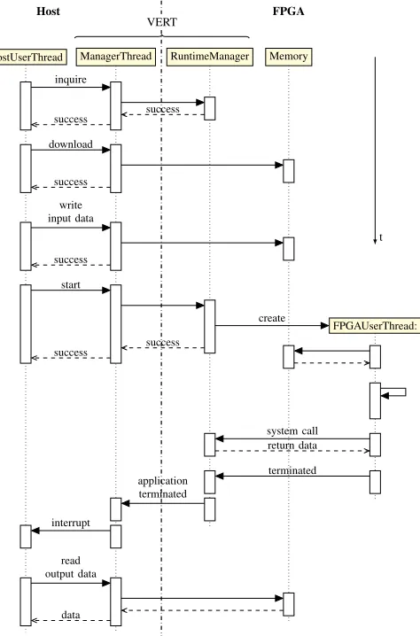
Figure 2. Sequence diagram for the lifetime of a typical application.
35µs if the operation is performed on the host, in contrast to2.9µs
if we use a local processor. By providing a local processor we thus offer the user the benefit of lower latency access to the memory which is shared with the accelerators. Moreover, by running the runtime manager on the local processor, we also reduce the latency associated with all hardware accesses, such as accelerator instantiation and execution control.
Users write applications for the host CPU where part of the
computations can be accelerated by the FPGA. To do so, our
toolchain generates anFPGA application packagewhich includes
the specifications of the hardware accelerators and code to be run on the local processor. This code is responsible for orchestrating accelerator execution and for performing serial computations with low-latency access to data on the FPGA memory shared with the accelerators.
Fig. 2 provides an example of how, when, and where the different parts of the application are executed. In order to start the FPGA application, the user thread on the host CPU passes the package to themanager thread, which deploys it to the FPGA. On the FPGA side, the runtime manager is responsible for allocating the resources
required by the FPGA user application, creating an FPGA user
[image:3.612.47.307.56.156.2]Hardware Module 0
Hardware Module N
...
Local processor
Local Memory Interrupt
Controller
Timer Control
Interface UART
PCIe Controller
Mas
ter/Sla
ve
Unit
Connec
on
Hub
Processor Sub-System Mutex
Clock gen.
[image:4.612.51.299.53.198.2]Clock gen.
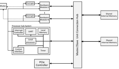
Figure 3. Structure of a basic hardware system to interface hardware accelerators on an FPGA with an application running on a host machine.
Prot. Checker
Prot. Checker
[image:4.612.49.300.234.385.2]Local processor
Figure 4. Overview of our hardware system, based on Fig. 3 with the addition of virtualisation hardware, partial reconfiguration (darker boxes), and message boxes for asynchronous communication (white boxes).
III. HARDWARESYSTEMDESIGN
Fig. 3 shows an example of a basic hardware system required to run an application on an FPGA connected to a host machine. The masters
in this system include the processor subsystem(local processor – a
MicroBlaze in the current implementation – and its peripherals), one or morehardware acceleratorsand aPCIe interfaceto communicate with the host machine, whereas the slaves are the shared internal (on
chip)memoryand shared external memory which, in our case, is the
DRAM on the FPGA board. Masters and slaves are interconnected
using the sharedbus.
In order to support the execution model described in Section II-B, we expanded the basic system shown in Fig. 3, resulting in that shown in Fig. 4. We replace the fixed hardware modules with a number of
partially reconfigurable(PR) regions, where user accelerators can be loaded at runtime. Using PR means the fixed infrastructure required
to manage accelerators is always present, in the static region of
the design, while accelerators can be loaded at runtime in the PR
slots.Isolatorsare used in order to disconnect the PR regions during
reconfiguration.
ID markermodules mark every bus transaction with an ID which identifies the application to which the corresponding master (PR
region or local processor) has been currently assigned1. The ID is
used to perform the virtual-to-physical address translation and to implement memory protection. In the current implementation, the on-chip memory available on the FPGA enables us to use a fully hardware
1In the current implementation, based on the AXI4 bus, AXI AxUSER lines
are used for this purpose.
page tablefor address translation and memory protection. Using the FPGA BRAM to store the page table makes TLBs unnecessary as the address translation latency (1 cycle on all transactions, 1 additional cycle in the case of page change) is already negligible compared to the latency of memory accesses (20 and 60–80 cycles for shared internal and external memory respectively), especially when burst accesses are used. We also leverage the MicroBlaze internal memory protection infrastructure to prevent user code from executing privileged instructions (such as disabling the interrupts) and from accessing the runtime manager code and data, as well as system peripherals. Our current system offers basic hardware virtualization and protection for this first experimental evaluation of the impact of these features on the performance of a complete working system. However, it is worth noting that these features in the static system can be easily updated in a manner that is completely transparent to the user. For instance, the hardware page table can be replaced by a TLB for every master to reduce FPGA BRAM usage and to increase flexibility in terms of page size.
Since users are given complete control of communication with their accelerators, we must ensure that faulty or malicious accelerators cannot cause downstream interconnect to fail due to a non-compliant
protocol implementation. To achieve this goal, aprotocol checker
actively checks the connections to the PR region for protocol violations. If a violation occurs, an interrupt to the local processor is raised and the module which caused the violation is removed. The corresponding application task running on the local processor is then killed and an error notification is sent to the host. In future, we plan to add a module which performs bus recovery in case a transaction leads to a hanged bus.
Finally, we providemessage boxmodules, through which
acceler-ators can raise an interrupt to the local processor in order to request services from the runtime manager (e.g., memory allocation and deallocation) and to communicate asynchronously with user code. The PCIe module can use the same mechanism to interrupt the runtime manager to, e.g., request the allocation of a new application or interact with user code running on the local processor. We also provide a
hardwaremutexwhich applications can use to synchronize multiple
accelerators.
IV. RUNTIMEMANAGER
The runtime manager is built on top of the MicroBlaze port of FreeRTOS, a simple open-source, multi-threading real-time operating system [11].
Specifically, our runtime manager consists of 4 FreeRTOS tasks, each of them responsible for the low level management of one of the hardware resources (memory, PCIe interface, partial reconfiguration, and accelerators). Tasks do not consume any processor time until the respective request queue is not empty. Requests can be generated
by other system tasks, interrupt service routines (ISRs), or user
applications via system calls. The local processor software provided by each user is also wrapped in a FreeRTOS task with lower priority than system tasks. This allows the FreeRTOS scheduler to allocate processor time among all active applications.
The only way user applications can access the hardware (accel-erators included) and request services from the runtime manager is by performing a system call. Examples of supported system calls include instantiating an accelerator in one of the PR locations, starting and stopping an accelerator, deallocating a previously allocated PR location, allocating and deallocating memory, obtaining a timestamp, and communicating with the application running on the host. In future, FreeRTOS’ facilities such as mutexes, semaphores and queues could be easily exposed via system calls in order to implement synchronisation and message passing between processes.
A. Host Interface
All host-runtime manager communication occur via a modified version of the DyRACT platform [12]. From the host side, the user can interact with the runtime manager via an API that invokes the manager thread, which in turn communicates with the FPGA via the DyRACT driver. Examples of supported operations include initializing and controlling the application running on the FPGA and performing high speed memory transfers from/to the FPGA memory.
B. PR Region Allocation
The PR task is responsible for serving PR requests from the applications. As for other shared resources (memory, processor time), we virtualise PR locations by only providing the users with a minimum number of locations that each application is guaranteed to receive
(MIN_LOC) and a maximum number of locations that can possibly
be allocated depending on the workload on the FPGA (MAX_LOC).
In this way, we provide a lower bound on the performance that each application can expect and at the same time give the opportunity to dynamically benefit from additional resources if and when available. These parameters can be different for each application and can be considered as in an advanced billing model.
Because all the applications share a single PR controller and a finite number of PR locations, the runtime manager might not be able to serve all PR requests immediately. In this case, requests are placed in a queue and served as soon as both the PR controller and one PR location become available. When an application does not require an accelerator any more, the corresponding location is simply flagged as free.
In the current implementation, all PR locations have the same size. However, it is straightforward to extend the methodology to support differently sized PR regions, as long as PR regions are always assigned as a whole. For example, the set of PR regions where each accelerator can be instantiated can be restricted based on accelerator resource requirements. At runtime, the PR task attempts to satisfy accelerator instantiation requests with the smallest available PR region in order to maximize resource utilization. Even when the PR regions all have the same size, it is still possible to scale the area and performance of an application by partitioning accelerators into multiple smaller replicas that operate in parallel [13], instantiated in different PR regions.
Since each PR operation requires a non-negligible time2, minimizing
the number of PR operations can result in a tangible reduction in the total execution time of an application. Hence, whenever an accelerator instantiation is requested, the PR task first checks if a previous instance of the same accelerator is already available in a location that has been flagged as available. If so, the PR task simply assigns the location to the application and returns immediately, thus saving the PR time. If not, the PR task randomly chooses a free location and proceeds with the PR operation. Loops containing sequential instantiations of different accelerators are an example of a situation where location
2In our experiments, 2–5 ms depending on accelerator resource utilization.
Local processor Local processor Host
[image:5.612.314.563.54.313.2]Static system
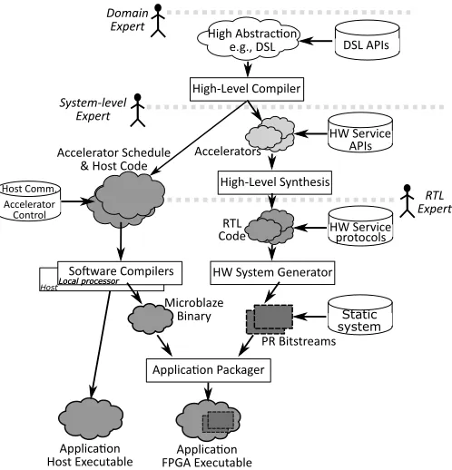
Figure 5. Design flow for our methodology. We define three entry points, depending on the user’s expertise, which eventually converge to the same type of output.
reuse can be advantageous; re-using accelerators still available from previous iterations can save considerable time for high iteration counts.
C. Memory Management
We implemented two levels of memory management. The memory management system task is responsible for the coarse memory administration, which consists of mapping or unmapping full memory pages (currently 1 MB) to/from each application’s virtual memory space. For instance, the memory management task is invoked to allocate the initial memory required for a new application to store partial bitstreams and user code.
Each application is also assigned a heap, which is a memory region dedicated to fine grained memory allocation and deallocation. For this purpose, we provide each application with a dedicated heap manager task. The heap manager is responsible for serving the dynamic memory allocation and deallocation requests within each application’s heap and for invoking the system memory manager to request an expansion of the heap if needed. We implement the heap manager as a separate task in order to be able to serve requests from local processor user code, accelerators, or host CPU user code, independently from the execution of the local processor user code. The heap manager features a message exchange area, that is a memory region guarded by a mutex, which the task itself uses to specify the parameters of a system call or to receive a message from other tasks (e.g., a new memory request). The mechanism used to implement the heap manager in the current version of the system can be extended and generalized to support multithreaded applications which share the same memory space and which can communicate with other application threads, accelerators, or host CPU code.
V. DESIGNFLOW
the cloud, we need to provide a design flow that facilitates users with varying expertise to develop applications targeting this infrastructure. Hence, our toolchain, illustrated in Fig. 5, offers three different entry points based on the user’s expertise and produces a package which can be deployed to the runtime manager.
A domain expert only needs to provide high-level DSL code. Similarly to George et al. [14], we use the Delite compiler [15] to decompose the application into sequential and parallel kernels and to infer the control flow graph. Parallel kernels are used to generate an HLS description, which is processed by the HLS tool (Vivado HLS 2015.4.2 in our case) to generate an RTL description of the hardware accelerators. Separately, the control flow graph is used to guide the generation of the local processor software which is responsible for running the sequential kernels and orchestrating execution of the accelerators. It also generates the additional software to be run on the host CPU which negotiates with the runtime manager the resources needed on the FPGA, sends the input data and retrieves the output data.
A user who needs more control of the HLS process can directly provide an HLS description of the accelerators. The design must match the specified interface specification and an API is exposed to allow interaction with the runtime manager (to, e.g., perform dynamic memory allocations).
Lastly, a third approach supports direct RTL description of acceler-ators, bypassing the HLS generation stage. This low-level approach is suitable for users with extensive hardware design expertise who require full control of accelerator design for performance maximization. As for the HLS case, an HDL interface and low level control specification for data access and interaction with the runtime manager are provided. HLS and RTL users must also provide the software which controls the execution of these hardware accelerators and performs any software computations required. Another API is provided to allow users to interact with their accelerators via system calls to the runtime manager, as detailed in Section IV. In our current implementation, the programs to be run on the local and the host CPU must be provided separately by partitioning the application as described in Section II-B. However, a parser can generate the two programs by decomposing a single piece of code based on user-specified directives or on the pattern of access to the FPGA memory and of interaction with the hardware accelerators.
Once the RTL description of the accelerators is available, the standard FPGA tool is invoked using a custom script. A set of partial bitstreams to implement the accelerators at runtime via partial reconfiguration is generated. To allow each accelerator to be instantiated in any of the PR regions, one partial bitstream per accelerator per PR region is generated. These partial bitstreams are based on the static system which we generated and downloaded to the FPGA offline and which contains the static part of the system. The partial bitstreams are in turn packaged together with the binaries for the local processor in a single file. This file contains all the information the runtime manager needs to properly allocate resources to the application (e.g., the number and size of each partial bitstream and the size of the local processor code) and all the data to be transferred to the FPGA. By using the APIs we provide, the software running on the host CPU can deploy the application to the FPGA by passing this package to the manager thread, which forwards it to the runtime manager, as described in Section II-B.
VI. RESULTS
A. Experimental Setup and Benchmarks
We evaluate the overhead of our proposed approach, by implement-ing the hardware and software infrastructure described in Section III
and IV, including 3 PR regions, on a Xilinx VC709 development board that hosts a XC7VX690T FPGA and has 8 GB of DDR3 memory, adapting the DyRACT framework [12]. Each application is
guaranteed to receive at least one PR region (MIN_LOC= 1) and can
potentially be assigned all the regions (MAX_LOC= 3). The following
applications have been used as benchmarks:
• PageRank (PRank)is a popular graph algorithm used in search
engines that iteratively computes the weights of each node in the graph based on the weights of the nodes with edges leading to it. We used a graph with 100,000 nodes and performed 10 iterations, each iteration consisting of two hardware accelerators invoked sequentially.
• Triangle Counter (TCount)counts the number of triangles in
a graph with 1,000,000 nodes. It is based on a single hardware accelerator, with the local processor only used to instantiate the accelerator and performing no computationally-intensive operation.
• Outlier Detector (Outl), a common kernel in machine learning applications [16], counts the number of outliers in a set of 100,000 2D points according to the criterion proposed by Knorr and Ng [17]. Similarly to TCount, it consists of a single accelerator design performing all the computationally-intensive operations. However, the workload can be parallelised among multiple clones of the accelerator, if available, similarly to the work done by George et al. [13]. The software tries to instantiate up to 5 such clones then starts all the accelerators that the runtime manager can provide.
• 1D Autocorrelation (ACorr), a common kernel in image processing applications, computes the autocorrelation of a 15,000-element floating-point vector. It consists of a 14,999-iteration loop where 3 accelerators with short execution time are invoked sequentially and the local processor performs 5 single and double-precision floating point operations.
Table I summarizes the properties and the parameters of each benchmark.
Benchmark Parameters Distinct accelerators
Accelerator invocations
Software workload
PRank 100,000 nodes 10 iterations
2 20 medium TCount 1,000,000
nodes
1 1 low
Outl 100,000 points
1 1-5 (in parallel)
low ACorr 15,000
points
3 47,997 high Table I
All the applications have been written in a high level DSL similarly to George et al. [14]. This allows us to demonstrate the entire toolchain. To simulate a scenario where only a critical part of the code of an application is executed on the FPGA, we closely followed the flow shown in Fig. 2. Specifically, the input data was generated by the host CPU on the host RAM and transferred to the FPGA RAM over PCIe. Similarly, the output data was retrieved from the FPGA to the host RAM, and the host CPU was used to verify the correctness of
the results. In the following, we callsetup timethe time required to
perform such data transfer operations, to negotiate with the runtime manager the resources required by the FPGA application, to download the application package to the FPGA, and to eventually free the allocated FPGA resources.
IEEE ACCESS 6
B R B R B R B R
0 20 40 60 80
PRank TCount Outl ACorr
Ex
ecution
time
(s)
PR Accelerators User code Runtime manager
B→Basic system
R→Runtime manager
B R
B R
B R
B R
0
20
40
60
80
PRank
TCount
Outl
ACorr
Ex
ecution
time
(s)
PR
Accelerators
User code
Runtime manager
B
→
Basic system
R
→
Runtime manager
B R
B R
B R
B R
0
20
40
60
80
PRank
TCount
Outl
ACorr
Ex
ecution
time
(s)
PR
Accelerators
User code
Runtime manager
B
→
Basic system
R
→
Runtime manager
B R
B R
B R
B R
0
20
40
60
80
PRank
TCount
Outl
ACorr
Ex
ecution
time
(s)
PR
Accelerators
User code
Runtime manager
B
→
Basic system
R
→
Runtime manager
B R
B R
B R
B R
0
20
40
60
80
PRank
TCount
Outl
ACorr
Ex
ecution
time
(s)
PR
Accelerators
User code
Runtime manager
B
→
Basic system
[image:7.612.53.302.57.222.2]R
→
Runtime manager
Figure 6. Breakdown of overhead components due to our infrastructure for all benchmarks. Except for ACorr, the total overhead is always less than 3%. The different structure of ACorr results in additional overhead due to the currently unoptimized implementation and is not an intrinsic limitation of the approach.
hardware accelerators. For this reason, we concentrate on the analysis of the features and requisite overheads of the infrastructure rather than on comparison with software implementations of the benchmarks.
All the measurements reported represent the average of the execution times for 5 runs; the standard deviation was always less than 1%.
B. Overheads
To evaluate the overhead associated with our virtualisation infras-tructure, we first run each benchmark separately and compare the execution time on our platform compared to that achievable with the basic system shown in Fig. 3. We divide the total runtime into four components:
• Accelerator execution: overall time spent by the application waiting for one or more accelerators to terminate.
• User code: local processor time spent in the user application.
• PR: overall time spent by the PR controller to perform PR
operations for the application.
• Runtime manager: local processor time spent in the runtime
manager code during application lifetime and setup time. For all applications, the setup time accounted for 8–40 ms depending on the size of the input and output data and on the number of partial bitstreams.
Results are shown in Fig. 6. For PRank, TCount and Outl, our approach introduces a total overhead of between 1% and 3%, mostly due to the additional latency that the page table and the second interconnect impose on every bus transaction. On the other hand, the overhead for ACorr reaches 54%. This is primarily due to a number of causes associated with the peculiar structure of ACorr compared to the other benchmarks:
1) A high count of short accelerator executions (about 45000, each of them lasting 1.35 ms on average), in contrast with a single (TCount, Outl) or a small number (20, for PRank) of longer accelerator executions.
2) A correspondingly high count of system calls, one per accelerator invocation.
3) A much more computationally intensive local processor workload on the MicroBlaze, consisting of 75000 floating point operations overall.
The higher overhead over the accelerator’s execution time is due to the shorter runtime of each accelerator invocation. Indeed, the execution of all accelerators generated by our toolchain from DSLs
S R S R S R S R S R S R
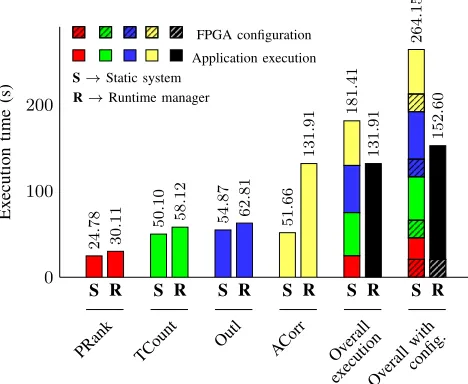
0 100 200 131 . 91 131 . 91 131 . 91 152 . 60 51 . 66 51 . 66 131 . 91 131 . 91 51 . 66 181 . 41 51 . 66 264 . 15 54 . 87 54 . 87 62 . 81 62 . 81 50 . 1 50 . 10 58 . 12 58 . 12 24 . 78 24 . 78 30 . 11 30 . 11
PRank TCount Outl ACorr Overall
executionOverall with config. Ex ecution time (s) FPGA configuration Application execution
S→Static system
R→Runtime manager
Figure 7. Comparison between simultaneously sharing the FPGA among multiple applications and providing exclusive use of the FPGA in a serial manner. Parallelising multiple applications reduces the overall execution time and, if the FPGA configuration time is taken into account, the performance improvement is even more significant.
starts with an initialisation sequence, consisting of several single-word reads to retrieve parameters and addresses of the input data. This represents a fixed-length overhead on accelerator execution time and could become relevant if the processing time is short, and the impact of the additional latency due to the page table is greater on these short reads compared to burst reads/writes that are mostly used during processing.
The high count of system calls, each of them requiring
approxi-mately185µson the MicroBlaze, is instead the cause of the increased
runtime manager overhead. The system call overhead could be reduced by introducing new system calls that can perform multiple accelerator instantiations with a single call.
Finally, the increased execution time for the user code is due to the current implementation, where the user code resides in the DRAM, a high-latency memory, in contrast to the basic system where all the code is executed from a local memory with a single-cycle latency. Indeed, the other applications suffered from increased code execution time, but because of the simpler operations completed by the local processor, user code execution time was still negligible compared to total execution time. We expect this overhead to be reduced by moving the user application code to a dedicated on-chip memory with reduced latency.
Importantly, in the case of the basic system, the FPGA must be reconfigured prior to starting application execution. This additional
step results in an increased effective execution time3 for the static
system. If the FPGA configuration is taken into account, the overhead of our infrastructure decreases and might even be negative, which is the case for all the benchmarks we consider here except ACorr.
In terms of area overhead, we measured a 3–5% increase in utilised LUTs, FFs and BRAMs, a 1% increase in memory LUTs and no impact on DSP utilisation.
C. Benefits of Sharing
To analyse the benefits of simultaneously sharing the FPGA compared to giving exclusive access to the whole FPGA to each application sequentially, we analysed the overall execution time of
[image:7.612.316.550.61.253.2]a workload comprising the 4 benchmark applications. By running more applications than PR regions (3), we also evaluated whether the overhead associated with continuous PR region allocation and partial reconfiguration can offset any gain obtained by simultaneously sharing the FPGA.
As shown in Fig. 7, even without considering the static FPGA configuration time, our approach reduces total execution time. This is due to the limited overhead that FPGA sharing imposes on the execution of each application, which is smaller than the sum of the execution times for all applications, and is a clear indication of the underutilization of FPGA resources if each application is given exclusive access to the whole FPGA. The gain resulting from FPGA sharing is even more significant if we take into account FPGA
configuration time4. Moreover, our approach is beneficial even when
the number of applications, each of them potentially requesting one PR location at the same time, is greater than the total number of PR locations physically available (in this example, 4 and 3 respectively). This demonstrates the validity of our resource allocation methodology, with no application suffering from resource starvation nor hogging all available resources.
D. Benefits of Dynamic Management
We also evaluated the advantages of the dynamic slot management we perform, compared to statically allocating tasks to slots as in other pieces of work [18], [10]. To do so, we compared the execution time of ACorr and Outl alone on a system with 1, 2, or 3 physical PR locations, where 1 PR location essentially represents the case of a static accelerator slot allocation [18]. The execution time of the other benchmarks did not show any dependence on the number of physical PR locations and thus is not reported here.
The results in Fig. 8 show that the performance of both applications scales according to the available resources. Outl can benefit from an underutilized FPGA by deploying multiple instances of the same accelerator on as many locations as the runtime manager can provide. ACorr, containing a loop where multiple hardware kernels have to be executed sequentially, can benefit from the location reuse feature described in Section IV-B with increased probability as the number of locations increases. These performance boosts for some applications directly result from the dynamic resource partitioning performed by the runtime manager in a manner completely transparent to the user, which would not be possible without resource virtualisation or with static allocation. Moreover, the software overhead required to implement these features was found to have a negligible impact on applications that cannot benefit from dynamic resource management because the PR time is in any case negligible or because the workload cannot be partitioned across multiple accelerators, as in the case of the other benchmarks.
VII. RELATEDWORK
FPGAs are being investigated for a variety of applications in the cloud and datacentre. They have been offered as a way to improve security and privacy by moving sensitive data processing into hard-ware to reduce possible attack vectors [19], [20]. High throughput complex data filtering and compression/decompression have also been demonstrated [21]. The Microsoft Catapult architecture [5] represents the first detailed application of FPGAs in an enterprise-level datacentre application. They are used to accelerate the document ranking part of the Bing search engine with hardware split across 8 FPGAs within a rack. The authors report almost doubled throughput in search ranking
4In the shared FPGA scenario, the FPGA configuration is performed only
once during boot, resulting in no actual overhead once the system is running.
1 2 3 1 2 3
0 100 200
7
.
78
226
.
70
8
179
.
78
8
.
37
79
.
92
1
.
96
·
10
−
3
56
.
25
0
.
22
29
.
46
0
.
22
21
.
14
ACorr Outl
Ex
ecution
time
(s)
[image:8.612.313.551.72.239.2]PR Accelerators User code Runtime manager
Figure 8. Breakdown of execution time for ACorr and Outl with differing numbers of available locations. When the FPGA is underutilized, the dynamic partitioning performed by our runtime manager can transparently boost the performance of some applications.
at a cost of only 10% increased power consumption and 30% increased total cost of ownership. Baidu have also presented FPGA-accelerated neural networks for recognition applications offering an order of magnitude better performance at minimal additional power cost [22]. All these represent fixed-function deployments.
More recent efforts have explored how FPGAs can be integrated into the cloud and shared among multiple users [18], [10]. These efforts partition FPGA resources into reconfigurable regions and use partial reconfiguration to dynamically deploy accelerators as we do. In Byma et al. [18], on-board memory is statically partitioned among accelerators making it impossible for regions to work in a producer-consumer fashion, a frequently occurring computational model, which is also used in two of our benchmark applications (ACorr and PRank). The work in Chen et al. [10] overcomes this limitation, but does not perform any dynamic management of accelerator slots. The ability to dynamically manage accelerator slots depending on runtime-varying workloads has been shown to be useful in applications such as ACorr and Outl in our evaluation. Additionally, in the architecture proposed by Chen et al., accelerators only access memory via DMA units in the FPGA static logic, which can be detrimental to the performance of accelerators that require sparse small irregular accesses. Our approach avoids this limitation and enables the memory interface of each accelerator to be customized based on its memory access pattern.
There have been previous efforts in the area of dynamic manage-ment of FPGA resources in embedded systems. This has included managing partial reconfiguration within Linux [23], abstracting partial reconfiguration control for adaptive systems [24], extending an RTOS to manage hardware tasks [8], and accessing the programmable logic in hybrid FPGAs from a microkernel hypervisor [25]. However, these are all system-on-chip scenarios with more tightly coupled communication that is not the case in a cloud-based deployment. Furthermore, the sharing and protection needed in a cloud setting are not considered. Another line of work dealing with FPGAs for high performance computing focuses more on optimising communication between a host and accelerator for maximum performance, in some cases offering reconfiguration of the accelerators [26]. However, these scenarios consider a single application requiring multiple accelerator tasks and do not consider sharing.
approach and overcome the memory wastage introduced by the fixed size pages we use. Other efforts, such as LEAP [27] and CoRAM [28] have investigated the creation of custom memory hierarchies to provide high performance memory systems to accelerators. We can utilize these techniques in conjunction with our approach to improve the performance of our memory system in the future. But our main objective in this work was to empirically study the performance overheads introduced by our memory virtualisation and protection techniques.
Recent open source FPGA interface frameworks have simplified integration of FPGAs with host PCs. RIFFA [29] is an established framework for integrating static accelerators with support for a range of boards and high PCIe throughput. However, it does not support partial reconfiguration, thereby requiring the full interface to be compiled into each accelerator design. DyRACT combines communication and reconfiguration over a single PCIe interface [12]. This overcomes the need for the extra cabling and drivers required to configure FPGAs in the traditional manner, which can be problematic in a tightly managed datacenter environment. It also virtualises the PCIe interface to allow a varying number of accelerators to exploit available bandwidth. We uses a modified version of DyRACT for host-FPGA communication.
VIII. CONCLUSIONS
FPGAs are an attractive computing platform for the cloud because of their energy efficiency and flexibility. To make FPGAs suitable for the cloud environment, we propose a methodology which enables developers to view FPGAs as a computational resource similar to CPUs, providing facilities such as memory management, virtualisation and a hardware abstraction layer. We also provide a design flow that enables developers to write FPGA-accelerated applications at differ-ent levels of abstraction, up to high-level DSLs where CPU-FPGA partitioning and interaction are done seamlessly. By implementing a simple but fully functional system, we have demonstrated that FPGAs can be virtualised with limited overhead, in terms of both area and execution time. Secondly, simultaneously sharing an FPGA among multiple applications is beneficial both in terms of overall execution time and effective device utilisation. Finally, dynamic partitioning of reconfigurable slots enables applications to benefit from additional resources whenever available. Therefore, this methodology represents a valid and feasible approach for integrating FPGAs in the cloud as a first class compute resource.
REFERENCES
[1] K. R. Jackson, L. Ramakrishnan, K. Muriki, S. Canon, S. Cholia, J. Shalf, H. J. Wasserman, and N. J. Wright, “Performance analysis of high performance computing applications on the Amazon Web Services cloud,”
inIEEE International Conference on Cloud Computing Technology and
Science (CloudCom), 2010, pp. 159–168.
[2] G. Lee, B.-G. Chun, and R. H. Katz, “Heterogeneity-aware resource allocation and scheduling in the cloud,”Proceedings of HotCloud, 2011. [3] P. K. Gupta, “IntelRXeonR+FPGA platform for the data center,” 2015, talk presented at FPL’15 Workshop on Reconfigurable Computing for the Masses. [Online]. Available: http://reconfigurablecomputing4themasses.net/files/2.2 PK.pdf
[4] J. M. Tendler, “An introduction to the POWER8 processor,” Presented at the IBM POWER User Group, Jan. 2014.
[5] A. Putnam et al., “A reconfigurable fabric for accelerating large-scale datacenter services,” in International Symposium on Computer
Architecture (ISCA), 2014.
[6] S. A. Fahmy, K. Vipin, and S. Shreejith, “Virtualized FPGA accelerators for efficient cloud computing,” inIEEE International Conference on
Cloud Computing Technology and Science (CloudCom), 2015, pp. 430–
435.
[7] H. Sidiropoulos, P. Figuli, K. Siozios, D. Soudris, and J. Becker, “A platform-independent runtime methodology for mapping multiple applications onto FPGAs through resource virtualization,” in2013 23rd
International Conference on Field programmable Logic and Applications,
Sept 2013, pp. 1–4.
[8] E. L¨ubbers and M. Platzner, “ReconOS: An RTOS supporting hard-and software threads.” in 2007 International Conference on Field
Programmable Logic and Applications. IEEE, 2007, pp. 441–446.
[9] Z. Xue and D. B. Thomas, “SysAlloc: A hardware manager for dynamic memory allocation in heterogeneous systems,” in25th International
Conference on Field Programmable Logic and Applications (FPL). IEEE,
2015, pp. 1–7.
[10] F. Chen, Y. Shan, Y. Zhang, Y. Wang, H. Franke, X. Chang, and K. Wang, “Enabling FPGAs in the cloud,” inProceedings of the ACM Conference
on Computing Frontiers, 2014.
[11] R. Barry,FreeRTOS reference manual: API functions and configuration
options. Real Time Engineers Limited, 2009.
[12] K. Vipin and S. A. Fahmy, “DyRACT: A partial reconfiguration enabled accelerator and test platform,” in24th International Conference on Field
Programmable Logic and Applications (FPL), 2014.
[13] N. George, H. Lee, D. Novo, M. Owaida, D. Andrews, K. Olukotun, and P. Ienne, “Automatic support for multi-module parallelism from computational patterns,” in 25th International Conference on Field
Programmable Logic and Applications (FPL), 2015, Sept 2015, pp.
1–8.
[14] N. George, H. Lee, D. Novo, T. Rompf, K. J. Brown, A. K. Sujeeth, M. Odersky, K. Olukotun, and P. Ienne, “Hardware system synthesis from domain-specific languages,” in24th International Conference on
Field Programmable Logic and Applications (FPL), 2014. IEEE, 2014,
pp. 1–8.
[15] H. Lee, K. J. Brown, A. K. Sujeeth, H. Chafi, K. Olukotun, T. Rompf, and M. Odersky, “Implementing domain-specific languages for heterogeneous parallel computing,”IEEE Micro, no. 5, pp. 42–53, 2011.
[16] V. J. Hodge and J. Austin, “A survey of outlier detection methodologies,”
Artificial intelligence review, vol. 22, no. 2, pp. 85–126, 2004.
[17] E. M. Knorr and R. T. Ng, “A unified notion of outliers: Properties and computation.” inKDD, 1997, pp. 219–222.
[18] S. Byma, J. G. Steffan, H. Bannazadeh, A. Leon-Garcia, and P. Chow, “FPGAs in the cloud: Booting virtualized hardware accelerators with OpenStack,” inProceedings of the IEEE International Symposium on
Field-Programmable Custom Computing Machines (FCCM), 2014, pp.
109–116.
[19] J.-A. Mondol, “Cloud security solutions using FPGA,” inIEEE Pacific Rim Conference on Communications, Computers and Signal Processing
(PacRim), 2011.
[20] K. Eguro and R. Venkatesan, “FPGAs for trusted cloud computing,”
in22nd International Conference on Field Programmable Logic and
Applications (FPL), 2012.
[21] P. Franciscoet al.,The Netezza Data Appliance Architecture: A Platform
for High Performance Data Warehousing and Analytics. IBM Redbooks,
2011.
[22] J. Ouyang, S. Lin, W. Qi, Y. Wang, and B. Yu, “SDA: Software-defined accelerator for large-scale DNN systems,” inHOT CHIPS, 2014. [23] J. A. Williams and N. W. Bergmann, “Embedded Linux as a platform
for dynamically self-reconfiguring systems-on-chip,” inInternational Conference On Engineering of Reconfigurable Systems and Algorithms
(ERSA), 2004.
[24] K. Vipin and S. A. Fahmy, “ZyCAP: Efficient partial reconfiguration management on the Xilinx Zynq,”IEEE Embedded System Letters (ESL), vol. 6, no. 3, pp. 41–44, 2014.
[25] A. K. Jain, K. D. Pham, J. Cui, S. A. Fahmy, and D. L. Maskell, “Virtualized execution and management of hardware tasks on a hybrid ARM-FPGA platform,”Journal of Signal Processing Systems, 2014. [26] E. El-Araby, I. Gonzalez, and T. El-Ghazawi, “Exploiting partial runtime
reconfiguration for high-performance reconfigurable computing,”ACM
Transactions on Reconfigurable Technology and Systems (TRETS), vol. 1,
no. 4, p. 21, 2009.
[27] M. Adler, K. E. Fleming, A. Parashar, M. Pellauer, and J. Emer, “Leap scratchpads: automatic memory and cache management for reconfigurable logic,” inACM/SIGDA International Symposium on Field Programmable
Gate Arrays. ACM, 2011, pp. 25–28.
[28] E. S. Chung, J. C. Hoe, and K. Mai, “CoRAM: an in-fabric memory architecture for FPGA-based computing,” in19th ACM/SIGDA
interna-tional symposium on Field programmable gate arrays. ACM, 2011, pp.
97–106.
[29] M. Jacobsen and R. Kastner, “RIFFA 2.0: A reusable integration framework for FPGA accelerators,” in23rd International Conference on