INTERTEC'S
5UPE~BRAlNTM
VIDEO COMPUTER SYSTEM. IMPORTANT NOTICE
This version of the SuperB rain Users Manual is intended for use with the .. SuperBrain or Sup~rBrain OD Video Computer Systems. However,.this manual is applicable only for those unfts with .Revision-Ot of the· Keyboarq/d~u module, and version 3.0 or.h ighe,rof the DOS and boot loader. If-ypu hav~ a Revision-OO :, .. Keyboard/CPU module, then use only the First or Second Edition of this manual.
Docum~nt No.68~1010 . . September 19?O
*** IMPORTANT ***
Do not attempt to write or save programs on your system diskette. It has been 'write protected' by placing a small adhesive aluminum strip over the notch on the right hand side of the diskette. Such attempts will result in a 'WRITE' or 'BAD SECTOR' error.
Before using your SuperBrain please copy the System Diskette onto a new blank diskette -an (ntertec 1121010 diskette. If you do not have such a diskette, contact you local dealer. He should be able to supply you with one. If you have any questions concerning this procedure please contact your dealer before proceeding. Failure to do so may result in permanent damage to your System Diskette.
AND
PROPRIETARY INFORMATION
Information presented in this manual is furnished for customer reference only and is subject to change.
This document is the property of Intertec Data Systems Corporation, Columbia, South Carolina, and contains confidential and trade secret information. This information may not be transferred from the custody or control of I ntertec except as authorized by I ntertec and then only by way of loan for limited purposes. It must not be reproduced in whole or in part and must be returned to Intertec upon request and in all events upon completion of the purpose of the loan.
Neither this document nor the information it contains may be used or disclosed to persons not having a need for such use or disclosure consistent with the pu rpose of the loan without the prior express written consent of I ntertec.
COPYRIGHT 1980
The following is a trademark of I ntertec Data Systems Corporation, Columbia, South Carol ina:
SUPERBRAIN
VIDEO COMPUTER SYSTEM
Your new SuperBrain Video Computer was manufactured at I ntertec's new 120,000 square foot plant in Columbia, South Carolina under stringent quality control procedures to insure trouble-free operation for many years. If you should encounter difficulties with the use or operation of your terminal, contact the dealer from whom the unit was purchased for instructions regarding the proper servicing techniques. I f service cannot be made available through your dealer, contact Intertec's Customer S.ervice Department at (803) 798-9100.
As with all Intertec products, we would appreciate any comments you may have regarding your evaluation and application for this equipment. For your convenience, we have enclosed a customer comment card at the end of this manual. Please address your comments to:
Product Services Manager I ntertec Data Systems Corporation
2300 Broad River Road Columbia, South Carolina 29210
The SuperBrain is distributed worldwide through a network of dealer/OEM vendors and through I ntertec's own marketing facilities. Contact us at (803) 798-9100 (TWX - 810-666-2115) regarding your requirement for this and other I ntertec products.
WILL THE MICROCOMPUTER YOU BUY TODAY STILL BE THE BEST MICROCOMPUTER BUY TOMORROW?
Probably the best test in determining how to spend your microcomputer dollar wisely is to consider the overall versatility of your terminal purchase over the next three to five years. In the fast-paced, ever-changing world·· of data communications, new features to increase operator and machine efficiency are introduced into the marketplace daily. We at Intertec are acutely aware of this rapid infusion of new ideas into the small systems business. As a result, we have designed the SuperBrain in such a manner as to virtually eliminate the possibility of obsolescence.
Many competitive alternatives to the SuperB rain available today provide only limited capability for high level programming and system expansion. Indeed, most low-cost microcomputer systems presently available quickly become outdated because of the inability to expand the system. Intertec, however, realizes that increased demands for more efficient utilization of programming makes system expansion capability mandatory. That means a lot. Because the more you use your SuperBrain, the more you'll discover its adaptability to virtually any small system requirement. Extensive use of "software-oriented" design concepts instead· of conventional "hardware" designs assure you of compatibility with almost any application for which you intend to use the SuperB rain.
Once you read our operator's manual and tryout some of the features described herein, we are confident that you too will agree with our "top performance -bottom dollar" approach to manufacturing. The SuperBrain offers you many more extremely flexible features at a lower cost than any other microcomputer we know of on the market today. The use of newly developed technologies, efficient manufacturing processes and consumer-oriented marketing programs enables us to be the first and only major manufacturer to offer such an incredible breakthrough in the microcomputer marketplace.
Browse through our operator's manual and sit down in front of a SuperBrain for a few hours. Then, let us know what you think about our new system. There is a customer comment card enclosed in· the rear section of this manual for your convenience.
INTRODUCTION
MAJOR COMPONENTS
SYSTEM OPERATION
INTRODUCTION TO CP/M FEATURES & FACILITIES
OPERATION OF THE CP/M CONTEXT EDITOR
CP/M 2.0 USER'S GUIDE FOR CP/M 1.4 OWNERS
OPERATION OF THE CP/M DEBUGGER
OPERATION OF THE CP/M ASSEMBLER
THE CP/M 2.0 INTERFACE GUIDE
THE CP/M 2.0 SYSTEM ALTERATION GUIDE
MICROSOFT BASIC 80 REFERENCE MANUAL
MICROSOFT UTILITY SOFTWARE MANUAL
SERVICE INFORMATION
HARDWAREADDENDUMS
SOFTWAREADDENDUMS
Section 1
Section 2
Section 3
Section 4
Section 5
-Section 6
Section 7
Section 8
Section 9
Section 10
Section 11
Section 12 I
Section 13
Section 14
•
INTRODUCTION
The SuperBrain Video Computer System represents the latest technological advances in the microprocessor industry. The universal adaptability of the SuperBrain CP/M* Disk Operating System satisfies the general purpose requirement for a low cost, high performance microcomputer system.
From the standpoint of human engineering, the SuperBrain has been designed to minimize operator fatigue through the use of a typewriter-oriented keyboard and a remarkably clear display. The SuperBrain displays a total of 1,920 characters arranged in 24 lines with 80 characters per line. The video display is usually crisp and sharp due to Intertec's own specially designed video driver circuitry. And, the high quality, non-glare etched CRT face plate featured on every SuperBrain assures ease of viewing and uniformity of brightness throughout the entire screen.
The SuperBrain's unique internal design assures users of exceptional performance for just a fraction of what they would expect to pay for such "big system" capabilities. The SuperBrain utilizes a single board "microprocessor" design which combines all processor, RAM, ROM, disk controller, and communications electronics on the same printed circuit board. This type of design engineering enables the SuperBrain to deliver superior, competitive performance.
Standard features of every SuperBrain include: two double-density, single-sided mini-floppies with a total of over 350,000 bytes formatted disk storage, 32K of dynamic RAM memory - expandable to 64K (in one 32K increment), a universally recognized CP/M* Disk Operating System featuring its own text editor, an assembler for assembly language programming, a program debugger and a disk formatter. Also standard are dual universal RS232 communications ports for serial data transmission between a host computer network via modem or an auxiliary serial printer. A number of transmission rates up to 9600 baud are available and selectable under program control.
Other standard features of the SuperBrain include: special operator convenience keys, dual "restart" keys to insure simplified user operation, a full numeric keypad complement, and a high quality typewriter compatible keyboard. An optional low cost S-100 bus adaptor is available to convert the Supel"Brain Z80A data bus into an S-100 data and address compatible protocol. The S-100 adaptor accommodates one S-100 printed circuit board which can be mounted internally.
For reliability, the SuperBrain has been designed around 4 basic modules packaged in an aesthetically pleasing desk-top unit. These major components are: the Keyboard/CPU module, the power supply module, the CRT assembly, and the disk drives themselves. Failure of any component within the terminal may be corrected by simply replacing only the defective module. Individual modules are fastened to the chassis in such a manner to facilitate easy removal and reinstallation. Terminal down-time can be greatly minimized by simply "swapping-out" one of the modules and having component level repair performed at one of Intertec's Service Centers. Spare modules may be purchased from an Intertec marketing office to support those customers who maintain their own "in-house" repair faci I ities.
The SuperB rain's cover assembly is exclusively manufactured "in-house" by I ntertec. A high-impact structural-foam material is covered with a special "felt-like" paint to enhance the overall appearance. Since the cover assemblyrs injected-molded, there is virtually no possibility of cracks and disfigurations in the cover itself. And, by manufacturing and finishing the cover assembly in-house, Intertec is able to specify only high quality material on the external and internal cover components of your SuperBrain to insure unparalleled durability over the years to come.
INTRODUCTION (continued)
A wide variety of programming tools and options are either planned or available for the SuperBrain. Standard software development tools available from I ntertec include Basic, Fortran and Cobol programming languages. A wide variety of applications packages (general ledger, accounts receivable, payroll, inventory, word processing, etc.) are available to operate under SuperBrain CP/M Disk Operating System from leading software vendors in the industry. Disk storage may be increased by adding SuperBrain's S-100 bus adaptor and connecting other auxiliary disk devices, including hard disk drives. And, another model of the SuperBrain - SuperB rain QD - features double density, double-sided disk drives which provide over 700,000 bytes of formatted data.
The price/performance ratio of the SuperBrain has rarely been equalled in this industry. By employing innovative design techniques, the SuperBrain is not only able to offer a competitive price advantage but boasts many features found only in systems costing three to five times as much. SuperBrain's twin Z80A microprocessors insure extremely fast program execution even when faced with the most difficult programming tasks. And, each unit must pass a grueling 48 hour burn-in before it is shipped to the Customer. By combining advanced microprocessor technology with in-house manufacturing capability and stringent quality control requirements, your SuperBrain should provide unparalleled reliability in any application into which it is placed.
FEATURE
CPU
Microprocessors
Word Size Execution Time
Mach ine Instructions I nterrupt Mode
Floppy Disk
Storage Capacity
Data Transfer Rate Average Access Time Media
Disk Rotation
Internal Memory Dynamic RAM
Static RAM
ROM Storage
CRT
Display Size Display Format Character Font Display Presentation
SYSTEM SPECIFICATIONS
DESCRIPTION
Twin Z80A's with 4MHZ Clock Frequency. One Z80A (the host processor) performs all processor and screen related functions. The second Z80A is "down-Ioaded" by the host to execute disk I/O.
8 bits
1.0 microseconds register to register 158
All interrupts are vectored and reserved.
Over 350K (700K + on SuperB rain aD) total bytes of unformatted data on two double density drives. Optional external hard disk storage can be connected using the optional S-100 bus adaptor.
250K bits/second
250 milliseconds. 35 milliseconds track-to-track 514 inch mini-disk
300 RPM
32K (64K on Superbrain aD) bytes dynamic RAM. Expandable to 64K in one 32K increment. Optional 32K is socketed.
1 K bytes of static RAM is provided in addition to the main processor RAM. This memory is used for program and/or data storage for the auxiliary processor.
2K bytes standard. Allows ROM "bootstrapping" of system at power-on.
12-i nch, P4 phosphor.
24 lines x 80 characters per line.
5x7 character matrix on a 7x 1 0 character field
Light characters· on a dark background.
*Specifications subject to chango without notice or liability.
SYSTEM SPECIFICATIONS (continued)
FEATURE Bandwidth Cursor Commu nications
Screen Data Transfer
Main Interface
Auxiliary Interface
Z80A Data Bus S-100 Bus
Parity
Transmission Mode Addressable Cursor System Utilities
Disk Operating System DOS Software Optional Software FORTRAN COBOL BASIC DESCRIPTION 15 MHZ.
Reversed image (block cursor)
Memory-mapped at 38 kilobaud. Serial transmission of data at rates up to 9600 bps.
RS-232C asynchronous. Synchronous interface optional.
Simplified RS-232C asychronous. Synchronous inter-face optional.
40-pin Data Bus connector.
Connector provided for connection of optional S-100 bus adaptor.
Choice of even, odd, marking, or spacing - under program control.
Half or Full Duplex. One or two stop bits. Direct Positioning by absolute x, yaddressing.
CP/M 2.2
An 8080 disk assembler, debugger, text editor and file handling utilities.
ANSI standard. Relocatable, random and sequential disk access.
ANSI standard. Relocatable, sequential, relative and indexed disk access.
Sequential and random disk access. Full string manipulation, interpreter.
Application Packages Extensive software development tools are available from leading software vendors including software for the following applications: Payroll, Accounts Receivable, Accounts Payable, Inventory Control, General Ledger and Word Processing.
Keyboard
Alphanumeric Character Set Generates all 128 upper and lower case ASCII characters.
SYSTEM SPECIFICATIONS (continued)
FEATURE
Special Featu res
Numeric Pad
Cursor Control Keys
I nternal Construction Cabinetry
Component Layout
Mounting
Environment Weight
Physical Dimensions
Environment
Power Requirements
DESCRIPTION
2-Key Rollover, Keyboard lock/unlock - under program control.
0-9, decimal point, comma, minus and
user-programmable function keys.
Up, down, forward and backward.
Structural foam
Four board modular design. All processor related functions and hardware are on a single printed circuit board. All video and power related circuits on separate single boards.
All modules mounted to base. CRT in a rigid aluminum frame. Disk Drive assemblies are mounted into special bracket for ease of servicing.
Approximately 45 pounds.
145/8" (H) x 21 3/8 (W) x 231/8 (D)
Operating: 00 to 400 C Storage: 00 to 850 C; 10 to 85% reI. humidity - non-condensing.
115 VAC, 60 HZ, 3 AMP (optional 230VAC/50HZ model available)
OPTIONAL VERSUS STANDARD FEATURES
Since each SuperBrain is designed utilizing the latest advances in microprocessor technology, many features which other system vendors offer as options are offered as standard features on th.e SuperBrain.
The SuperBrain Video Computer is designed to satisfy the universal requirement for a low cost, high performance small business system and, hence, there are virtually no options from which to choose. Basically, available options for the SuperBrain include:
BASIC 80 FROM MICROSOFT - an extensive implementation of Basic language available for Z80 microprocessors. In just three years of use, it has become the world's standard for microcomputer Basic. Basic 80 gives users what they want from a Basic - ease of use plus all of the features that make a micro perform like a minicomputer or large mainframe. Basic 80 meets the requirements of the ANSI subset standard for Basic and supports many unique features rarely found in other Basics.
MICROSOFT FORTRAN 80 - comparable to Fortran compilers on large mainframes and minicomputers. All of ANSI standard Fortran X3.9-1966 is included except the COMPLEX datatype. Therefore, users may take advantage of the many application programs already written in Fortran. Fortran 80 is unique in that it provides a microprocessor Fortran and assembly language development package that generates relocatable object modules. This means that only the subroutines and system routines required to run Fortran 80 programs are loaded before execution. Subroutines can be placed in a system library so that users develop a common set of subroutines that are used in their programs. Also, if only one module of a program is changed, it is necessary to recompile only that module.
CENTRONICS-COMPATIBLE PARALLEL INTERFACE(1) - connects directly to SuperBrain's 40 pin Z80A data bus connector and provides for a parallel output as required for Centronics-compatible printers.
S-100 BUS ADAPTOR (2) - connects to SuperBrain's auxiliary Z80A data bus edge card connector and provides for the connection of up to one standard sized S-100 bus board inside the SuperBrain cabinet. Bus adaptor includes ribbon cables, S-100 conversion circuitry, S-100 card guides and a metal mounting bracket to enable the S-100 bus adaptor to be installed on the inside cover just to the right of SuperBrain's twin double-density disk drives.
SYNCHRONOUS INTERFACE - enables synchronous transmission via the auxiliary RS232 serial communications port.
32K DYNAMIC RAM EXPANSION KIT - a set of sixteen 16K RAM chips which plug into existing sockets on the SuperBrain Keyboard/CPU module to enable expansion of the SuperB rain's dynamic memory from 32K to 64K. Also included with the RAM kit is an additional CP/M DOS Diskette which reconfigures the SuperBrain's Operating System to accommodate all 64K of RAM.
(1) Available June, 1980 (2) Available June, 1980
I
INTERNAL CONSTRUCTION
Perhaps the most remarkable feature of the SuperB rain is its modular construction using only four major subassemblies which are clearly defined in their respective functions so as to facilitate ease of construction and repair. These four subassemblies are shown in figure one and described below.
isl< Drive Module
Keyboard/CPU Module
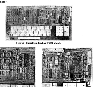
INTERNAL CONSTRUCTION (continued) KEYBOARD/CPU MODULE
The control section of the SuperB rain Video Computer is based upon the widely acclaimed Z80A microprocessor. The result is far fewer components and the ability to perform a number of functions not possible with any other approach. The Keyboard/CPU module (figure two) contains the SuperBrain's twin Z80 microprocessors. One Z80A (the host processor) performs all processor and screen related functions while the second Z8QA can be "downloaded" to execute disk I/O handling routines. The result is extremely fast execution time for even the most sophisticated programs.
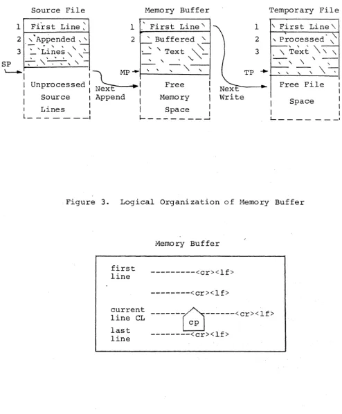
[image:28.615.152.533.316.671.2]In addition to containing the SuperBrain's microprocessor circuitry, the Keyboard/CPU module contains 32K of dynamic RAM with sockets for an additional expansion capability of 32K (see figure three). Also found on this module is: the character and keyboard encoder circuitry, the "bootstrap" ROM, the disk controller and all communications electronics. Power is supplied to and signals are transferred from this module via a single 22 pin ribbon cable connected to the SuperBrain's main power supply module. Connection of this module to the disk drive subassemblies is via a separate ribbon cable. Figure four shows the connectors on the Keyboard/CPU module which are used for interconnecting this module with the disk drive subassemblies, the main power supply and the optional parallel and/or S-100 bus adaptor.
Figure 2 - SuperBrain Keyboard/CPU Module
Figure 3 - Dynamic RAM Section
[image:28.615.91.295.504.678.2]Every SuperBrain is equipped with 32K dynamic RAM - on board expandable to 64K. 16 sockets are provided for the additional 32K of RAM.
INTERNAL CONSTRUCTION (continued)
CRT DISPLAY MODULE
The CRT Display Module consists of a 12 inch, high resolution, cathode ray tube mounted in a rigid aluminum chassis. The faceplate of the CRT is etched in order to reduce glare on the surface of the screen and provide uniform brightness throughout the entire screen area . The CRT display presentation is arranged in 24 lines of 80 characters per line.
[image:30.613.96.528.250.609.2]The CRT video driver circuitry is mounted in the base of the CRT chassis to facilitate ease of removal and subsequent repair. I n this manner, either the CRT itself or the video circuitry can be easily exchanged without disrupting any of the other major modules within the terminal (see figu re five).
Figure 5 - SuperBrain CRT Display Module
This module is easily removed for service or replacement. A single edge connector is provided for connection to SuperBrain's Power Supply Module.
INTERNAL CONSTRUCTION (continued) MAIN POWER SUPPL V MODULE
The SuperBrain's power supply is a "solid-state, switching" design and employs switching voltage regulators to provide many years of trouble-free service. This design reduces heat dissipation and allows for efficient cooling of the entire terminal with a specially designed whisper fan to reduce environment noise. The entire power supply can be easily removed by unscrewing the three screws holding it into the base of the terminal. Included on the main power supply module are the power off/on switch, the user brightness control and the main and auxiliary RS232 serial ports. By combining the power supply section and external serial communications connections on the same module, the total module count is able to be kept to a minimum thus greatly facilitating ease of field service repair while at the same time minimizing the number of modules required to be stocked to effect competent field repair (refer to figure six).
Figure 6 - Main Power Supply
INTERNAL CONSTRUCTION (continued)
DISK DRIVE MODULES
[image:34.615.172.447.198.440.2]Figures seven and eight illustrate the left and right views of the SuperBrain's specially designed double-density disk drive subassembly. Each SuperBrain contains two of these type drives which are mounted conveniently just to the right of the CRT display module on a rugged aluminum mounting bracket which supports the drives so that they are flush mounted with the front "bezel" of the unit. Power to these drives is derived from the Power Supply Module located just behind the drive assemblies themselves. Data to and from these drives is routed via a single 34 pin ribbon cable connecting the drives to the Keyboard/CPU module.
[image:34.615.154.447.474.718.2]Figure 7 - Top View of SuperBrain Drive Assembly
Figure 8 - Bottom View of SuperBrain Drive Assembly
INTERNAL CONSTRUCTION (continued)
The 8uperBrain can be configured to employ an optional module - the 8-100 bus adaptor. This adaptor plugs into the 8uperBrain's Keyboard/CPU module and mounts internally on the metal bracket supporting the disk drive assemblies. ,Figure nine shows the 8uperBrain with the 8-100 bus adaptor and a single 8-100 printed circuit card. Figure ten shows the same unit without the 8-100 bus module installed.
The 8-100 bus adaptor is offered as an optional feature on the 8uperBrain for those users who desire to expand the units' capability with the addition of auxiliary disk devices including the new, more popular Winchester-type drives.
A single 8-100 card can be easily inserted in the card guide supplied with each 8-100 bus adaptor (as shown in figure eleven). NOTE: The 8-100 bus adaptor includes cabling, connectors and circuitry to convert the 8uperBrain's Z80 data bus into the 8-100 bus. The actual 8-100 compatible printed circuit board (as is shown in figure eleven) is supplied by the user.
Figure 9 - 8uperBrain with 8-100 Bus Adaptor and card installed.
Figure 10 - 8uperBrain with 8-100 Bus Adaptor and card removed.
Figure 11 - SuperBrain S-100 Bus Adaptor
[image:36.617.322.521.301.456.2] [image:36.617.99.297.301.454.2] [image:36.617.179.437.495.696.2]THEORY OF OPERATION
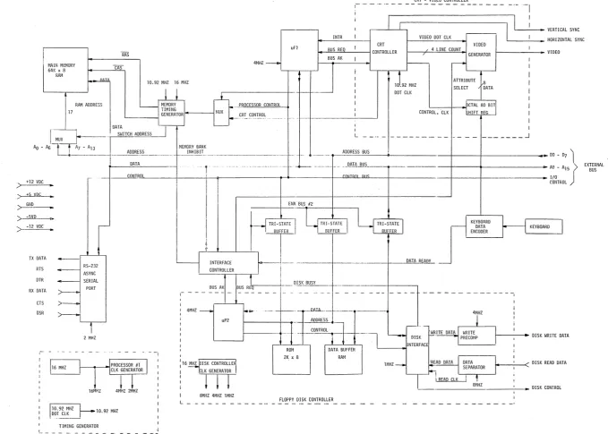
The SuperBrain contains two Z80 microprocessors. (Reference Figure 3-1) uP1 is the master processor. It communicates with the 64K RAM and the I/O devices (serial port, keyboard encoder, interface controller, and CRT controller). Aside from these devices, it can also access the 2K ROM and DATA BUFFER RAM in the FLOPPY DISK CONTROLLER. uP2 is slaved to uP1 and can only access the 2K ROM, DATA BUFFER, and the DISK INTERFACE. This processor is used exclusively for disk control.
The 32/64 kilobyte main memory consists of up to thirty-two 16K x 1 bit dynamic RAMS. These are divided in four banks (0-3) with each bank containing 16 kilobytes of storage. The RAS-CAS timing sequence necessary for memory access is created by the memory timing generator.
There are two devices that can access memory - uP1 and the CRT Controller. uP1 can read and write to memory while the CRT Controller can only perform the read function. Because each device runs at a different speed, two clock frequencies are required for memory timing. The speed is determined by the selection of the control input to the timing generator. The microprocessor functions require the faster clock.
The CRT-VI DEO CONTROLLER contains three main devices - the CRT Controller which generates all the timing signals for data display; the video generator which produces the character font; and the octal 80-bit shift register which stores one row of video data. (80 characters)
The CRT Controller generates all the timing necessary to display 24 rows of characters with 80 characters per row. Thus the screen can display a total of 1920 characters. These characters are stored in the CRT refresh buffer which is the upper 2048 bytes (2K) of RAM.
Because the CRT buffer is not a separate buffer and the processor must also use the same bus to access memory, this bus must be timeshared between the two. This is accomplished by the CRT controller performing a direct memory access (DMA) cycle which is done at the beginning of each scan row. Each scan row is divided into ten scan lines, therefore during the first scan line time, the controller takes control of the processor bus by generat-ing a bus request. After acquirgenerat-ing the bus, it reads 80 characters from the CRT buffer and loads them into the 80 x 8 shift register. This data is then recirculated in the buffer for the next nine scan lines to produce one row of video characters. Therefore, there are twenty-four DMA cycles performed per vertical frame.
There are also twenty-five interrupts generated - one for each row scan and one extra during vertical blanking. During the first twenty-four, the processor sets or resets the video blanking depending on whether that row is displayed or not. During the vertical blanking interrupt, the address registers in the CRT controller are initialized to the correct top-of-page address and the cursor register is also updated.
The Interface Controller is basically three 8 bit I/O ports (8255). Through this device, the processor can obtain status bits from other devices and react to the status by setting/ resetting individual bits in the 8255.
The Keyboard Encoder scans the keyboard for a key depression, determines its position, and generates the correct ASCII code for the key. The processor is flagged by the 'Data
Ready' signal via the I nterface Controller. The character is then input by the processor.
THEORY OF OPERATION (continued)
The remaining I/O device is the RS-232-C Serial I nterface Port. Presently, it operates only in the asynchronous mode and adheres to a simplified standard protocol. The baud rate is set to 1200 baud by the operating system (Refer to the Technical Bulletin enclosed at the end of this manuaL)
As previously mentioned, uP1 has the capability of communicating with the RAM and ROM in the FLOPPY DISK CONTROLLER. It does this to obtain the bootloader from ROM on power-up and system reset and also when transferring disk parameters and data to/from the Data Buffer RAM. Because the amount of main memory used is the maximum that the processor addressing can support different 16K banks of main memory must be switched off line when communicating with the disk RAM or ROM. In these cases Bank 0 (0000H-3FFFH) is switched out when communicating with the ROM, and Bank 2 (8000H-BFFFH) when communicating with the RAM.
The DISK CONTROLLER performs all disk related I/O functions upon command from the main processor. These commands are:
• Restore to track
0
• Read sector • Write sector
• Write sector with deleted data mark • Format
The parameters associated with drive, side, track, and sector numbers are loaded, a status word is set at specified location in the disk RAM. When uP2 receives this status, it sets the 'disk busy' status bit and performs the indicated function. Upon completion, it resets the 'busy' bit thus allowing the main processor (uP1) to retrieve data and status from the RAM.
POWER
MEMORY
MICROPROCESSOR SERIAL PORTS CRT SCREEN
FLOPPY DISKS
DOS
GENERAL SPECIFICATIONS 110/220 VAC 50/60 HZ
Dual Switching Power Supplies 32/64K bytes (dynamic) Two Z80's operating at 4MHZ
Two asynchronous 'simplified' RS-232-C, programmable ports 24 lines, 80 columns
7 x 10 dot character field 5 x 7 dot character font 50/60 HZ refresh rate
Two, 5-1/4", double density, MFM
Format (Soft sectored) - 512 Bytes/sector; 10 sectors/track 35/70 tracks/diskette Capacity - 179K bytes formatted single sided, 35 tracks/diskette 358K bytes formatted single sided, 70 tracks/diskette CP/M, Version 2.2
MAIIl MEMORY 64K x B
RAI~
i--=l
RAM AODRESS
17
. +12 VOC
;:;
..
) +5 VOC
> GNO
> -5VD
) -12 VDC
..
,--JIX DATA
-=f'"
RTS
ASYNC OTR SERIAL
PORT RX DATA
>---CTS > -DSR
>---~
2 MHZ,-16MHZ RAS CAS CONTROL INTR uFf BUS REO
BUS AK 4MHZ ___
10.92 MHZ 16 MHZ
-
-,
--1--+
J..ROCESSOR CONTROL ._. __ CR!.CONTROL ... -.. -- ·1-- .. 1. ...
-~---,
I
L _____ • _ _ _ _ _ _ _ _ _ • _ _ _ _
I
_______ ..J
MEMORY BANK INHIBI~_ . __ . _ _ . _ _ ._. __ -1-- ~_ _ ____ . ..-ADDRESS BUS
4P
l , _. __ . ___ 1._ +-- _____ .J--___ P.!lIiI..ill!? ___ -,--_ - - - - i +
-.---+---+---~---~
INTERFACE _._____ DATA R 8!!L.
CONTROLLER
I
BUS AK Ij DISK BUSY BUS REQ ..
---+--DATA ENCODER
f
KEYBOARD1-
- - - 14MHZ ---001 1.1>r ---l--.~..JlAIJL- - - 1 4MHZ uP2 ADDRESS
J
T1-
CONTROLI
1I
1 - - - 1--1""-T'1
l~ I ' ~ IWRITE DAT~ WRITE -~ OISK I PRECOI-IP '--_ _ ... -tIINTERFAC
16 MH~ISK CONTROLLE 1
-! LIGETT 8MHZ 4MHZ 1 MHZ L
ROM 2K x B
DATA BUFFER
RAM
FLOPPY DISK CONTROLLER
lMHZ_
8fIHZ
I
KEYBOARD
10.92 MHZ
_ _ _ I
TIMING GENERATOR
- - - - _ . _
-FIGURE 3-1 SUPERBRAIN KEYBOARD/CPU MODULE BLOCK DIAGRAM
•
DO -07
I
AO - A15
>
1/0
j
[image:44.791.60.740.46.531.2]INSTALLATION AND OPERATING INSTRUCTIONS
UNPACKING INSTRUCTIONS
Be sure to use extreme care when unpacking your SuperBrain Video Computer System. The unit should be unpacked with the arrows on the outside facing up. Once you have opened the unit, locate the Operator's Manual which should be placed at the front of the terminal. If you have ordered additional optional software with your system, it will most likely be attached to the outside of the carton in a gray envelope. Extreme care should be used in opening this envelope so as not to damage any of the delicate diskette media contained inside. The MASTER SYSTEM DISKETTE is located inside the front cover of the Operator's Manual. Be careful not to discard or misplace this diskette as it will be vital for the operation of the equipment in later sections. .
Now that you have located your Operator's Manual and system diskette you can proceed to remove all packing material on the top and front of the terminal. Once this has been accomplished, you may now remove the terminal from the shipping carton. In some instances, you may notice that the terminal is somewhat difficult to remove from the carton. This is due to the varying amounts of packing material that is placed in each carton. If you should experience such difficulties, rotate the carton on its side. With the terminal on its side, you should now be able to pull outward on the terminal and separate it from the box. Once the terminal is out of the carton place it on a table and remove the protective plastic bag which should be surrounding the terminal. DO NOT DISCARD THE SHIPPING CARTON UNTI L YOU HAVE COMPLETELY CHECKED OUT THE TERMINAl.
SET UP
Now that you have removed your SuperBrain Video Computer System from its packing carton, you are ready to begin to set up the system. The first step in this procedure is to verify that your SuperBrain Video Computer System is wired for a line voltage that is available in your area. This can be ascertained by looking on the serial tag located at the right rear of the terminal. This tag should indicate that your unit is set up for either 110 or for a 220 VAC operation. DO NOT ATTEMPT TO CONNECT THE SUPERBRAIN VIDEO COMPUTER SYSTEM TO YOUR LOCAL POWER OUTLET UNLESS THE VOLTAGE AT YOUR OUTLET IS IDENTICAL-TO THE ONE SPECIFIED ON THE BACK OF YOUR TERMINAl. Should the voltages differ, contact your dealer at once and do not proceed to connect the SuperBrain Video Computer System to the power outlet.
Before connecting the SuperBrain Video Computer System to the wall outlet, be sure that the power switch located at the left rear corner is turned OFF. You may now proceed to connect your computer system to the wall outlet. After completing this connection, turn the power switch to the 'ON' position. At this time, you should hear a faint"whirring" sound coming from the fan in the computer. After approximately 60 seconds the message 'INSERT DISKETTE INTO DRIVE A' will appear on the screen. If this message does not appear on the screen after approximately 60 seconds, depress the RED key located on the upper right hand corner of the numeric key pad. This key is the master system reset key and should reinitialize the computer system thereby displaying the 'I NSE RT' message on the
scre~n. If, after several attempts at resetting the equipment you are unable to get this message to appear on the screen, turn the unit off for approximately 3 to 5 minutes and then reapply power to the unit. If you are still unable to get the appropriate message to appear on the screen, contact you r I ntertec representative.
SYSTEM DISKETTE
INSTALLATION AND OPERATING INSTRUCTIONS (continued)
that a small adhesive aluminum strip has been placed over the notch on the right hand side of the diskette. This aluminum strip is used to "WR ITE PROTECT" the diskette. Therefore, you may only load and/or read programs off of this diskette. If you wish to write or save programs on the system diskette it will be necessary to remove the small adhesive aluminum strip from the diskette. This is NOT RECOMMENDED as it will subject your diskette to accidental errors that may be induced by you while you are getting familiar with the operating system.
You are now ready to proceed with inserting the system diskette into the machine. When facing the front of the machine, you will notice that tliere are two small openings on the right-hand side of the machine. The first opening (the one furtherest to the left) is designated as DRIVE A. The second opening (the one on the right-hand side of the terminal) is designated as DRIVE B. This distinction is extremely important since the disk operating system can only be loaded from DRIVE A.
Now that you have located the two disk drives on the system, open the disk drive door on DRI VE A (opening closest to your left). The drive can be opened by applying a very slight pressure outward on the small flat door located in the center of the opening. Once the Drive door has been opened, you are now ready to insert the Operating System Diskette. As noted previously, this is the diskette which was packed with your Operator's Manual. The front of the diskette should contain a small white sticker located in the upper left hand corner of the diskette. This diskette should contain a message indicating that it is the SuperBrain DOS Diskette with CP/M Version 2.0. Once you have located this diskette you may insert it into the machine. Be careful to insure that (1) the small aluminum write protect strip is orientated towards the top edge of the diskette and that (2) the label located in the upper left hand corner of the operating system diskette is facing AWAY from the screen towards the right-hand side of the terminal. Once you have orientated the diskette in this fashion, you may now insert it into the terminal. It is EXTREMELY important that the diskette be properly orientated before inserting it into the machine since improper orientation will not allow the operating system to properly load. Once the diskette has been placed in the machine, be sure that it has been inserted all the way by applying a gentle pressure on the rear edge of the diskette. Once you are certain that the diskette is fully inserted, you may close the disk drive door. This can be accomplished by applying a slight pressure on the door pulling it back into the direction from which it was originally opened. Once you have closed the door, you will notice a small "swishing" sound. This sound is normal and indicates that the computer is now attempting to load the operating system. Some drives are quieter than others and therefore this noise may not be audible in some cases.
After closing the door the following message should appear in the upper left-hand corner of the screen:
XXK SUPERBRAIN DOS VER X.X A"?
INSTALLATION AND OPERATING INSTRUCTIONS (continued)
After you have checked the orientation of the diskette try reinserting it into DRIVE A (do NOT insert the system diskette into DRIVE B as it will not load from DRIVE B). Once the diskette has been reinserted, close the door on DRIVE A and depress the RED key. If after several repeated depressions of the RED keys the message XXK SUPERBRAIN DOS VER X.X does not appear on the terminal then contact your dealer.
REVIEWING THE SYSTEM DISKETTE
Now that you have successfully loaded the System Diskette and Disk Operating System, (DOS), the SuperBrain is ready to accept your disk operating system commands. At this time we will review several of the commands in the operating system. However, it is recommended that you refer to the appropriate section in this Manual for a detailed description of all such commands (Section 4 - Introduction to CP/M Features and Facilities). The most used system command is the DI R command. This command directs the operating system to display the directory of all programs contained on the system diskette. You may enter this command by simply typing the letters DI R on the keyboard. After you have typed these letters, it is necessary to depress the RETURN key. Depressing this key instructs the computer to process the line of data that you have just typed. After you depress the RETURN key the computer should respond by displaying all of the programs on the system diskette. These programs will appear in the following form:
A: ED.COM A: DDT.COM A: ASM.COM A: LOAD.COM A: DUMP.COM
A: SYSGEN:COM A: PIP.COM A: STAT.COM A: SUBMIT.COM
To obtain a better understanding of just what this information means, lets take a look at the first line:
A: ED.COM
The first letter on this line is a letter A. This tells you that the information following this letter is located on DRIVE A. The colon serves as a separator between the Drive designator ("A") and the file NAME and file TYPE. The file NAME is, in this case, "ED" and the file TYPE is "COM". As such, this line tells the operator that a program called ED (the disk operating system text editor) is located on the "A" drive and is a COM type of file. A more detailed treatment of this information can be found in section 4 of this manual.
IMPORTANT NOTE: Some of the disk utility programs have a two digit number suffixed to the File name (i.e. PIP 22). This suffix is used to indicate the actual revision and/or version level of the program.
DUPLICATING THE OPERATING DISKETTE
Now that you have successfully loaded the Disk Operating System on Drive A, it is important to duplicate this diskette onto another disk. This is necessary in order to preserve the original copy of the diskette and guard against any possible damage to the original media. To generate a copy of the operating system you will first need a NEW BLANK DISKETTE. We recommend an Intertec 1121010 diskette for this purpose. If you do not have any blank diskettes of similar quality, please contact the representative from whom you purchased your equipment. He should be able to supply you with an ample quantity of these diskettes.
Once you have located a new blank diskette, insert it into DRIVE B. Follow the procedures outlined in the previous paragraphs regarding the insertion of the operating system diskette. The only difference is that you will be inserting the new blank diskette into DRIVE B. Be sure and leave the system diskette installed on DRIVE A.
INSTALLATION AND OPERATING INSTRUCTIONS (continued)
Once you have installed the new blank diskette on DRIVE B, you are now ready to "FORMAT" the new diskette. It is necessary to format all new previously unused diskettes before attempting to' transfer data to them. This is necessary because all information is stored on diskettes in what is known as the SOFT SECTORED FORMAT which necessitates the writing of certain information on the disks before user programs can be stored on them.
To format the disk in DRIVE B enter the command 'FORMAT' at the keyboard. Remember ·to depress the key marked RETURN after typing the words FORMAT. The operating system should now respond by asking you to select the type of diskette being formatted (S or D). This question asks whether the diskette to be formatted is single sided or double sided. Unless you have ordered our new Quad Density SuperBrain QD, the response to this question should be the letter "S" indicating a single sided diskette. After entering the'S' depress the RETURN key. The operating system will now ask you whether you have a 64K (6) or 32K (3) disk operating system. In most cases, the answer to this question will be 3 (32K). After you have entered the appropriate response to this question the operating system will respond by telling you to place a blank diskette on DRIVE B. Since this has already been done, we are now ready to proceed with formatting the diskette and may do so by entering the letter "F". At this point and time you will hear the disk drive reset to track
a
and begin the formatting process. When a disk is formatted the read/write head positions to tracka
and rewrites each track (there are a total of 35 on each diskette). The screen will also display the current track which is being formatted. This number should range froma
to 34 for a total of 35 tracks.After the disk has been completely formatted, the operating system will respond by asking you whether to "REBOOT" the operating system or whether you wish to format another disk. If you wish to format another disk, remove the newly formatted disk from DRIVE B
and insert a new blank diskette into DRIVE B. You may now proceed to format this new diskette by once again entering the letter "F". If you do not wish to format any more diskettes, simply enter a RETURN.
The Operating System should now reload and once again be ready to accept new commands.
Since the intent of this procedure was to copy the original disk operating system we are now ready to begin that procedure. This can be accomplished by entering the following command on the keyboard:
2~
V
PIP B: =*.*
After you have entered the above command at the keyboard depress the return key.
The system will now begin to copy all of the programs on DRIVE A over to DRIVE B. As each program is copied, its name will be displayed on the screen. This procedure takes approximately 5 to 10 minutes. After the procedure completes, the control of the operating system will be returned to the user.
.•
Now that you have completed copying the operating system's programs from the A DR I VE to the B DRIVE it is necessary to copy the disk operating system itself (which is located on tracks 0, 1 and 2) onto the DRIVE B. This may be accomplished by entering the following command at the keyboard:
SYSGEN 2..7-_
The SYSGEN command is used to generate an operating system and place it on the desired
INSTALLATION AND OPERATING INSTRUCTIONS (continued)
disk. Once you have entered this command at the keyboard and typed RETURN, the disk operating system will ask you to select which drive that you want to take the source from. The correct answer to this question is the letter "A". After entering "A" depress the
RETURN.
The next question the program will ask is where do you want the source to be placed (the destination drive). The correct answer to this is the letter "B" indicating DRIVE B. Once you have entered this, the operating system will be copied from DRIVE A onto DRIVE B.
After this process has been completed the operating system will ask you whether you wish to duplicate another copy or to reload the operating system. The correct response is to simply enter a RETURN which will reload the operating system.
Once the operating system has been reloaded, you may now remove the master disk operating system in DRIVE A. Once this disk has been removed store it in a safe place as you may need it later to generate additional copies of the disk operating system and its programs.
At this point you should have removed the master disk from DRIVE A. Now remove the copy from DRIVE B and reinstall it on DRIVE A and close the door on DRIVE A. After you have completed this, depress the RED reset keys located on either side of the keyboard. This will reset the machine and reload the newly installed operating system off of your new diskette.
IMPORTANT: If random garbled information is displayed on the screen at this time, this indicates that you have made an error in the use of the "SYSGEN" program. If this is indeed the case, then remove the new diskette from DRIVE A and reinstall the original master system diskette and repeat the previously outlined procedure for generating a new disk operating system. If you still encounter difficulties, please refer to Section 4 of this manual for more detailed information concerning this procedure.
Now that you have successfully completed the generation of a new system diskette please refer to Section 4 of this manual for a complete description of all of the operating systems utility programs (DDT.COM, PIP.COM, SUBMIT.COM, etc.).
OPTIONAL SOFTWARE
Numerous optional software packages are available for use with your SuperBrain Video Computer System. Currently available directly from Intertec are such software packages as Microsoft's BASIC, FORTRAN and COBOL. If you would like additional information on these packages please contact you r local I ntertec representative.
NEWLY RELEASED SYSTEM PROGRAMS
From time to time, Intertec will be releasing additional 'standard' system programs. Listed below is a brief description of several such programs. A complete description of these and other similar programs can be found in the "software addenda" section of this manual.
INSTALLATION AND OPERATING INSTRUCTIONS (continued)
RAMTST.COM This program runs an extensive test on main memory by writing and reading all possible patterns into all locations in the RAM. This program takes approximately 4 to 5 minutes to complete on 32K machines and 8 to 10 minutes on 64K machines. Since different amounts of RAM are contained in the 32 and 64K machines, we have included two RAM test programs. These are: RAMTST32.COM and RAMTST64.COM which are for testing 32 and 64K versions of the SuperBrain Video Computer System. It is important to note that the 64K RAM test program will not execute properly on a 32K machine.
At the end of the RAM test program, the message RAM OK will appear on the screen if the test was completed successfully. If any errors were detected during the test, the computer's bell will turn on and continue in a continuous tone manner until the RED reset key is depressed. If a continuous tone such as this is heard on the computer when executing the RAM test, depress the RED reset and try executing the program several times. If the program continues to produce the audible tone, then please contact the I ntertec Service Department.
CONFIGUR.COM This program allows the user to configure all parameters for the RS232 MAIN and AUXILIARY serial port. The selected configuration is then permanently stored on the disk along with the disk operating system. As such, the system will be completely reconfigured each time power is applied to the machine or the RED reset key is depressed.
A complete description of all of these programs can be found in the software addenda section of this manual. In addition to the descriptions contained therein, most newly released system programs will contain a description program along with the actual COM file. This program will be in the form of FILE NAME.DES. As an example of such a program would be 'FORMAT.DES'. This program .would contain a description of how the format program operates. Therefore, if you are unable to find an adequate description in the software addenda section of this manual for a program on the disk, please check for a DES version of the program on your disk. If such a program exists, you may display the instructions by simply typing the following command: TYPE FI LENAME.DES.
VIDEO DISPLAY FEATURES AND CONTROL CODES
Various screen control features are available to the operator through the use of 'ESCAPE' sequences. Among these are the following:
Absolute cursor addressing
Erase to end of line
Erase to end of page
Display control characters
[ESC] [Y] [row] [column] The cursor is positioned to the row and column specified. Refer to the SuperBrain screen layout for specific screen formatting information. [ESC] [en] [K] Data is erased from cursor position to the end of the current line.
[ESC] [en] [k] Data is erased from cursor position to the end of the screen.
[ESC] [en] [E] Enable transparent mode. Control characters received are displayed on the screen and are not executed.
INSTALLATION AND OPERATING INSTRUCTIONS (continued)
Disable control character display [ESC] [U')] [D] Disable the transparent mode. Other features are also available using the 'CONTROL' key. They a-re the following:
MASTER RESET FEATURE
CONTROL [A] CONTROL [F] CONTROL [G] CONTROL [I] CONTROL [K] CONTROL [L] CONTROL [U]
- Home cursor (Row 1, Column 1) - Cursor forward
- Ring Bell - Tab - Cursor Up - Clear Screen - Cursor Back
A Master Reset of all terminal hardware may be accomplished by depressing the solid colored RED key located on the upper right hand corner of the numeric keypad. It is important to note that on some versions of the SuperBrain, this reset feature may involve the depression of two RED keys. If this is the case on your computer system, you will notice that the two RED keys are located on the right and left corners of the alphameric section of the keyboard.
CURSOR CONTROL KEYS
INTERFACING INFORMATION
RS-232-C Serial Interface
The following chart illustrates the pinouts for the MAIN and AUXI LlARY serial ports and the direction of signal flow.
SUPERBRAIN SERIAL PORT PIN ASSIGNMENTS
MAIN PORT
PIN #
1 \3UJ
.2 1"3K'I'\
3 BLI\
4 \'1,,):(
5 Gr~!
6 0\((,
7 \,UHT
15 CRI,)
17 YEL 20 IZE"fJ 22 F;:'I--I_
241.,\3'[;;1-)
AUXI LlARY PORT
PIN #
1
2
3 7
20
(For use with Revision 3.0 DOS software or higher and Keyboard/CPU Module Revision 1.0 or higher)
ASSIGNMENT
GND
Transmitted Data Received Data Request to Send Clear to send Data Set Ready GND
Transmit Clock Receive Clock Data Terminal Ready Ring Indicator Clock
ASSIGNMENT
GND
Received Data Transmitted Data GND
Data Terminal Ready Bus Adaptor Interface
DIRECTION (From SB) (To SB) (From SB) (To SB) (To SB) (To SB) (To SB) (From SB) (ToSB) _ (From 58)
DIRECTION
(To SB) (From SB) (ToSB)
The SuperBrain contains a Z80 bus interface to the main processor bus. These signals are shown in the chart on the following page.
PIN CONNECTIONS FOR EXTERNAL BUS
SIGNAL
PIN NAME DESCRIPTION
1 SPARE
2 SYSRES* System Reset Output, Low During Power Up Initialize or Reset Depressed
3 SPARE
4 A10 Address Output
5 A12 Address Output
6 A13 Address Output
•
7 A15 Address Output
8 GND Signal Ground
9 A 11 Address Output
10 A14 Address Output
11 A8 Address Output
12 OUT* Peripheral Write Strobe Output 13 WR* Memory Write Strobe Output
14 SPARE
15 RD* Memory Read Strobe Output
16 SPARE
17 A9 Address Output
18 D4 Bidirectional Data Bus
19 IN* Peripheral Read Strobe Output 20 D7 Bidirectional Data Bus
21 SPARE
22 D1 Bidirectional Data Bus
23 SPARE
24 D6 Bidirectional Data Bus
25 A0 Address Output
26 D3 Bidirectional Data Bus
27 A1 Address Output
28 D5 Bidirectional Data Bus
29 GND Signal Ground
30 D0 Bidirectional Data Bus
31 A4 Address Bus
32 D2 Bidirectional Data Bus
33 SPARE
34 A3 Address Output
35 A5 Address Output
36 A7 Address Output
37 GND Signal Ground
38 A6 Address Output
39 +5V 5 Volt Output (Limited Current)
40 A2 Address Output
NOTE: * implies negative (Logical "0"') true, Input or Output
-! @ # $ %
ESC 1 2 .3 4 5
TAB Q W
i
Ei
R TCTRL CAPS LOCK A S D F
SHIFT Z X C V
A &
.
( ) - +-
BACK6 7 B 9 0 = , SPACE
1 I LINE
Y U I 0 P I DEL
[ "- FEED
G H J K L : ;
..
.
I I RETURN B N M < > 7 SHIFT HERE/ IS
SPACE BAR
SUPERBRAIN KEYBOARD LAYOUT A
BREAK·
7
4
1
B 9 ,
5 6
-2 3 E
N
T
E
0 R
RESTART
-..
t
-! @ # $
ESC 1 2 3 4
TAB Q W E R
CAPS
CTRL LOCK A S D
RE-SHIFT Z X C START
t
I
Special "re-start" sequence key used in conjunction with other re-start key on right side of keyboard wi \I re-Ioad SuperBrain's Disk Operating System_ A two-key re-start sequence is used to minimize chance of operator error when system is in operation. Both keys must be depressed simultaneously to reload the operating system.
%
5
T
F
V
1\ &
.
( ) - + ~ BACK6 7 B 9 0 : , SPACE BRK
1 I
LINE
Y U I 0 P I DEL
[
"
FEED :..
IG H J K L ; I RETURN B N M < > 7 / SHIFT HERE IS START
RE-SPACE BAR
I
SUPERBRAIN KEYBOARD LAYOUT B
7
4
1
B 9 I
5 6
-2 3 E
N T E
0 R
II
.-...
t
- I
"-1'
I"I"I-I~I-I'
1'1'1'1+1· H ·1/1'1' 1'1' 1'1'1-1'1-1'1·1·1+1' 1'1·1'1'1' 1'1
'l'I'I4ft'1 '1'1
'l'I'I'j
f
2~
f.+
W x Y zCl'
-i
I I
3 "
4 It
5
6 ~
88-
9U-10
11 •
12 +
13
14
-15
16
17 0
18 I
111 I
201
2114~
22 IS
I-2311
:14 11
/'
24 lines
80 Characters
SCREEN DISPLAY
, J
This Screen Format of the lntertube's display area provides an easy method of locating and addressing specific screen positions. Using the ESC, Y, r, c command,locate both the row character (r = 1 - 24) and the column (c = 1 ·80) characters. Example:
ROW
1 (Home) 2
20
COLUMN
50
COMMAND
ESC Y SP sp ESC Y S ESC Y 3 Q
An application programmer may find it helpful to maintain a table of row and column numbers with their respective addressing characters as shown on this Screen Format. This will provide quick and easy access to specific screen positions.
I I I I I I I I I I I I I I I I I I I I I I I I I I I I I I I I I I I I I I I I I I I I I I I I I I I I I I I I
I-t 2 3 4 Ii I 7 8 II 1 1 2 3 4 Ii I 7 8 9 Z 1 2 3 4 Ii 8 7 8 II :I 1 2 3 4 Ii 8 7 8 9 4 1 2 3 4 5 6 7 8 9 5 1 2 3 4 5 6 " 8 9 6 1 2 3 4 5 6 7 8 9 7 1 2 3 4 5 6 7 8 9 8
o 0 0 0 0 0 0 0
INTERPRETING THE ASCII CODE CHART
The figure below illustrates a conventionally arranged ASCII code chart divided into three sections corresponding to control codes (columns 0 and 1) upper case characters (columns 2,3,4, and 5), and lower case characters (columns 4 and 5) .
~
..
00 00 010 01 100
1 1 111
~b5
..
.
0 1 1 01 10B. b
~ ~ ~ column
It 4
~
s
~ ~ ~ ·1 a 1 2 3 4 5 6 7
0 a 0 0 a NUL DLE SP 0 @ P , p 0 a 0 1 1 SOH DCI ! I A 0 a q
0 a 1 a 2 STX DC2 " 2 B A b r
0 0 1 1 3 ETX DC3 /I 3 C S c s
0 1 0 0 4 EOT DC4 $ 4 D T d t 0 1 0 1 5 ENO NAK % 5 E U e u
0 1 1 0 6 ACK SYN & 6 F V f v
0 1 1 1 7 BEL ETB 7 G W 9 w 1 0 0 0 8 BS CAN ( 8 H X h x
1 0 0 1 9 HT EM ) 9 I Y i y
1 0 1 0 10 LF SUB
.
J Z j z1 0 1 1 11 VT ESC + K I: k I
I
1 1 0 0 12 FF FS < L \ L I
I
1 1 0 1 13 CA GS - = M. J m I I
1 1 1 0 14 so AS < N 1\ n
-1 1 1 1 15 SI US / ? 0 - 0 DEL
Control codes are not displayable unless in the transparent mode. Some of these codes affect the state of the terminal when they are received by the display electronics. For example, the code SOH causes the cursor to go to the home position, and code DC2 turns on the printer port. Codes which have no defined function in the Super8rain software are ignored if received. The set of 64 upper case alphanumeric characters is sometimes referred to as "compressed ASCII".
If the terminal is set for upper case operation only (CAPS LOCK), lower case alpha characters from the keyboard are automatically translated and displayed as their upper case equivalents (columns 4 and 5). If the DE L code is received, it is ignored. Lower case characters received from the input RS-232C port are displayed as lower case.
I
INTRODUCTION TO
01
[)~[j~Tfll
RESEflRl:tI
Post Office Box 579, Pacific Grove, California 93950, (408) 649-3896
AN INTRODUCTION TO CP/M FEATURES AND FACILITIBS
COPYRIGHT (c) 1976, 1977, 1978 DIGITAL RESEARCH
Copyright (c) 1976, 1978 by Digital Research. All rights reserved. No part of this publication may be reproduced, transmitted, transcribed, stored in a retrieval system, or translated into any language or computer language, in any form or by any means, "electronic, mechanical, magnetic, optical, chemical, manual or otherwise, without the prior written permission of Digital Research, Post Office Box 579, Pacific Grove, California 93950.
Disclaimer