MODEL SQ706A DISK CONTROLLER (HOST ADAPTER)
FOR
SCSI INTERFACE
INSTALLATION AND OPERATION MANUAL
16 October 1989
~II
DISTRI.BUTED. LOGIC CORPORATIONn~~
~565 i~xs~~~gir StreetAnaheim. California 92806 I I Telephone: (714) 937·5700
SECTION 1
SECTION 2
SECTION
3
TA~LE
OF CONTENTS
DESCRIPTION
.
.
. . .
.
..
.
. .
.
.
. .
.
PAGE
1-1
CHARACTERISTICS. • • . • • • • • • • • • 1-2 Supports 22-Bit Addressing • • . • • •• 1-2 Supports SCSI Common Command Set For
Disk Drives: • • . • • . • • • 1-2 SCSI Pass-Through Mode •• ~'.
i',... •
1-2 Full S,CSI Implementation ••• •y..
1-2-Onboard Formatting 1-2 ,
Automatic Diagnostic Self Test • • • •• 1-2 Onboard Bootstrap PROM . • • • • • • •• 1-2
Reassignment of Bad Blocks 1-2
16-Entry Command Queue • • • • • • • • • 1-3 Single SCSI Command. • • • • • • 1-3 Disk Drives Supported. • • • • 1-3 CONTROLLER SPECIFICATIONS • • • 1-7
INSTALLATION
.
. .
. . . .
.
HARDWARE BOOTSTRAP JUMPERS CONTROLLER INSTALLATION
OPERATION • • • • • • •
INITIATING COMMUNICATION
. . .
.
.
Via Controller Serial Port • • • • • Via Virtual Terminal • • • • • • •
Procedure for Bringing Up··the Virtual Terminal Via the LSI~11 With Host Adapter Boot Enabled Procedure for Bringing Up the
Virtual Terminal Via the LSI-11 With Host Adapter Boot Disabled. Procedure for Bringing Up the
Virtual Terminal Via the MicroVAX II • • • • • CONFIGURATION MENU • • • • • • • • •
Standard Diagnostics . . • • • • • • Host Memory DMA Test • • • • • • . Display Controller Characteristics • Set Controller Characteristics •
How to Find Current Address . For LSI-11 System
SECTION 4
SECTION 5
Figure 1-1
Figure 2-1 Figure 2-2 Figure 2-3
Table 1-1
Table 1-2 Table 1-3
Table 2-1
Table 3-1
DIAGNOSTICS
TABLE OF CONTENTS (Continued)
· .
.
.
.
PAGE
4-1
SETU P AND SELF TEST . • . • . 4-1 FRONT END TEST-ZRCFB3 . . . 4-2 DISK EXERCISlrR-ZRCDA 1 . . . . • . /.... 4-4 MICROVAX II MDM-KDA50-Q . . . . ,.. • 4-8 Fun c t ion a 1 T est . . • . • . t. (1 • • 4 - 8
Exerciser • • .. .. • . • • 4-9
Utility . . . . 4-9
ERRORS AND TROUBLESHOOTING
·
.
. .
. .
.
.
.
GENERAL . . • . . . • . . .
ERROR LOGS . . • • . • . • • • .. • SCSI Host Memory Access Error Log Disk Transfer Error Log • • • • . SDI Error Log . . . • . • • . Self-Detected Fatal Port/Controller
Errors • . • • . • • • • • •
LIST OF ILLUSTRATIONS
Disk Syste~, Simplified . . . ~
Controller Configuration • • • • MicroVAX II Backplane (Typical) MicroVAX II H9278 Backplane • • •
LIST OF TABLES
Controller/Q-Bus Interface Lines Module)
. . .
.
.
. .
·
·
Controller to Drive - J2·
Controller to Terminal-
J4·
Jumper Configuration
. · · ·
.
·
SECTION 1
DESCRIPTION
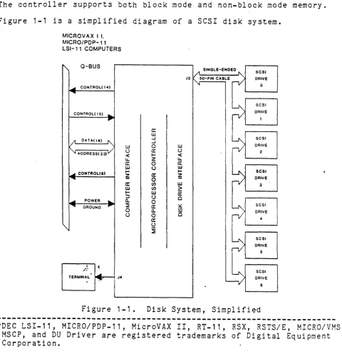
This manual describes the installation and operation of Distributed Logic Corporation (DILOG) Model SQ706A Disk Controller. This control-ler is a host adapter which may communicate wi th ei ther an embedded controller in the ~rive or a bridge controller, which is a controller that communicates with more than one drive. -The controller is a dual-module board that interfaces up to seven SCSI disk drives with DEC* LSI-11/23, -11/23 PLUS, 11173, MICRO/PDP-11 and MicroVAX II computer systems. The controller is software compatible with DEC DU drivers (MSCP) in RT-11, RSX-11M+, RSTS/E, MicroVMS, ULTRIX, UNIX, and MUMPS.
The controller supports both block mode and non-block mode memory.
Figure 1-1 is a simplified diagram of a SCSI disk system.
MICROVAX I I, MICRO/PDP-11 LSI-11 COMPUTERS
~ Q-BUS
-"""II1II CONTROL( \4)
...
CONl'ROL(15) ...
~
l;t CATA( Ie) ~
~ AOORESS(22)V
[image:4.617.71.551.234.730.2]-"""II1II CONTROLca)
...
-"""II1II POWER
...
~ CiROUND ~
'"
;~ t
TERMINAL
.
~ J4-W () < IJ.. a: w ;-~ a: W
..-:J a. ::E 0 U~ SINGLE-ENDED " - SCSI
J2 ~50-PIN CABLE
rV
CRIVE0
~
SCSICAlVE
1
a:
w
-I
~ SCSI
-I
0 w
nI
CRIVEa: () 2
..-
<Z IJ..
0 a:
(J W
..-
~ SCSIa: ~ ORlve
0
n/
(J) w 3
(J) >
w
a:
(J 0
0
a: ~
~
SCSIa. ~ CAlVE
0 0
a: 4
(J
~
~
SCSI CRIVE5
~
SCSI CRIVECHARACTERISTICS
Characteristics of the controller are as follows:
o SUPPORTS 22-BIT ADDRESSING
o
The controller supports 16-,
1B-,
and 22-bit Q-bus addressing.SUPPORTS SCSI COMMON COMMAND
The controller is compatible with SCSI
Co~m;n
Command Set for disk drives and connects up to seven SCSI' ul1its (either disks with embedded SCSI interface or SCSI controller/disk combina-tions). The following SCSI commands are, used by the host adapter:FORMAT INQUIRY MODE SENSE READ
READ CAPACITY
REASSIGN BAD BLOCKS REQUEST SENSE
START/STOP
TEST UNIT READY WRITE
o SCSI PASS-THROUGH MODE
The controller has.a commands di rectly from desired unit.
special mode which permits passing SCSI the host through the controller to the
o FULL SCSI IMPLEMENTATION
The controller offers a full SCSI implementation including dis-connect/reconnect and synchronous data transfers.
o ONBOARD FORMATTING
The onboard formatter uses either the system console or a DLV11-compatible connector to provide interactive terminal access. The formatter is menu driven and also provides controller and drive test options.
o AUTOMATIC DIAGNOSTIC SELF TEST
The controller is suppl ied wi th an onboard automati c sel f-test diagnostic that is activated each time power is applied. These diagnostics are run repeatedly until the controller is brought online.
o ONBOARD BOOTSTRAP PROM
o REASSIGNMENT OF BAD BLOCKS
The controller will handle media flaws by issuing a SCSI Reassign command.
o 16-ENTRY COMMAND QUEUE
o
The controller can queue up to 16 commands for up to seven units. Each unit has a command queue so that the 16 commands may be dis-tributed among the drives in any fashion.
SINGLE SCSI COMMAND
The configuration menu allows a single SCSI command to be man-ually entered and sent to the target.
o DISK DRIVES SUPPORTED
The controller is compatible with ANSI SCSI spec X3T9.2/85-52 Rev
4B for Direct Access devices. The coupler is compatible with
disk drives from such manufacturers as:
CONTROL DATA IOMEGA
MICROPOLIS PRIAM
TOSHIBA
FUJITSU KODAK
MINISCRIBE RODIME
HITACHI MAXTOR
NORTHERN TELECOM SIEMENS
For additional drive support, contact the factory.
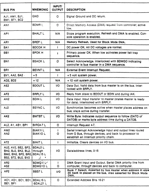
Table 1-1 lists the Controller/Q-Bus Interface Signals, Table 1-2
Table 1-1. Controller/Q-Bus Interface Lines (Dual Module)
BUS PIN
,
I
INPUTII
I
MNEMONICI
OUTPUTI
DESCRIPTIONI
AJ 1, AM 1, BJ 1 , GND 0 Signal Ground and DC return.
I
BM', BT', BC2 J
I AN1 BDMA L I 0 I D!roct Mamoii ACCeSS (DMA} i6Qu65t irum controiier; active !
I
low. I
AP1 BHALT L N/A Stops program execution. Refresh and OMA Is enabled. Con· sole operation Is enabled.
AR1 BREF L N/A Memory Refresh. Used for Block Mode OMA. BA1 BDCOK H I DC power OK. All DC voltages are normal.
8Bl BPOK H i I Prlmaiy power OK. vVnen iow activates power fall trap sequence.
eN1 BSACK L 0 Select Ackn9wledge. Interlocked with BOMGO Indicating , controller Is bus master In a OMA sequence.
SR' SeVNT L N/A External Event Interrupt Request. BV', AA2, BA2 . +5 I + 5 volt system power.
A02, BD2 +12 N/A + 12 volt system power.
AE2 BDOUT L I/O Data Out. Valid data from bus master Is on the bus. Inter· locked with BRPLY.
AF2 BRPLY L 110 Reply from slave to BDOUT or 80!N and durIng IAK. AH2 BDIN L I/O Data Input. Input transfer to master (states master Is ready
tor data). Interlocked with BRPLY.
AJ2 BSYNC L I 1/0 Synchronize: becomes active when master places address on
j
I
bus; stays active during transfer.
AK2 BWTBT L I/O Write Byte: Indicates output sequence to follow (DATO of
I
DATOB) or marks byte address time during a DATOB. AL2 A1 AB1 BP' ,BIAQ4·7 L 0 ' Interru p t Re uest 4·7. q
AM2 BIAKll L I Serial Interrupt Acknowledge Input and output lines routed AN2 BIAK10 L 0 from
a
Bus, through devices, and back to processor toestablish an Interrupt priority chain. AT2 BINIT L Initialize. Clears devices on 110 bus. AU2, AV2, BE2, BF2, BDALO L
BH2, BJ2, BK2, BL2, through 1/0 Data/address lines, 0·15
8M2, BN2, BP2, BR2, BDAL 15 L BS2, BT2, 8U2, BV2 ; .. ~ t
AR2 BOMGll V' I DMA Grant Input and Output. Serial OMA priority line from AS2 BDMG10 L 0 computer, through" devices and back to computer.
t
AP2 BBS7 L 110Bank 7 Select. Asserted by bus master when address In upper 4K bank is placed on the bus. Also asserted for Block Mode DMA.
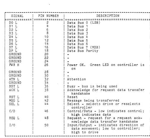
[image:7.626.51.544.84.712.2]Table 1-2. Controller to Drive - J2
SIGNAL
I
PIN NUMBER1
DESCRIPTION============1==============1========================================
DO L 1 2 1 Data Bus 0 (LSB)
D1 L
r
4 1 Data Bus 1D2 L I 6 t Data Bus 2
D3 L : 8 : Data Bus 3
"D4 L 1 0 : Da ta Bus 4
D5 L 12 I Data Bus 5
D6 L 14 Data Bus 6
D7 L 16 Data Bus 7 (MSB)
DP L 18 Data Bus Parity
GROUND 20
GROUND 22
GROUND 24
PWR H 26 Power OK. Green LED on controller is
GROUND GRQUND ATN L GROUND
BSY
L
ACK L
RST L MSG L SEL L
C/D
REO L
I/O 28 30 32 34 36 38 40 42 44 46 48 50 on Attention I I
-I Busy - bus is being used
I Acknowledge for request data transfer
handshake Reset
Message being transferred
Select - selects drive or reselects controller
Control/Data - low indicates control; high indicates data
Request - request for a request ack-nowledge data transfer handshake Input/Output - indicates direction of
~ata movement; low to controller; high to drive
-~---~---~---
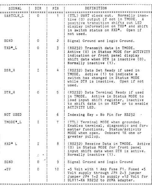
[image:8.617.59.565.84.549.2]Table 1-3. Controller to Terminal - J~
r===;i;~~~---i--~i~-=I==;i~==~=---~~Fi~i~I;~-~=---====1
'=============1=======1======= ======================================="
UARTCLK_L I 0 : 1 (TTL) UART clock out. Normally
inac-I I tive (0) output if not in THODE. A
I
I ! ! nr.cdt-iHO t-l""!:ln~it-ir.n ~h,f't-~ !""In1- rt'T") .
, di~pl;y~i;f;~~;ti;~ ;~-TXD*~;~d~;hift ,I
SGND
NOT USED
TMODE*_L
RXD* L
SGND +5V
o
o
Io
I Io
o 2 3 4 5 6 7 8 9 10in switch status on RXD*. Open if
not used.
Signal Ground and logic Ground.
(RS232) Transmit data in THODE. . . I
Active (OJ in Status MODE for ACTIVITY
indication or front panel display shift data when DTR is inactive (0). Normally inactive (1).
(RS232) Data Set Ready if used in
TMODE. Active (1) to indicate a
switch has changed in Status MODE
while DTR is inactive. Open if not
used.
(RS232) Data Terminal Ready if used
in TMODE. Active in Status MODE to
load input shift register, inactive to shift data in on RXD* or to enable ACTIVITY LED.
Indexing Key - No Pin for RS232
(TTL) Terminal MODE when grounded. Enables terminal, diagnostic and
for-matter functions. Status/Activity
MODE when open. Onboard 1K ohm or
greater pullup.
(RS232) Receive Data in THODE. Active
(0) in Status MODE for front panel
input shift data when
DTR
is active.Normally inactive (1).
Signal Gropnd and logic Ground
+5 Volt with 1 Amp Fuse F1. Fused +5
j
Volt supply through JP4 2-3 jumper Jumper JP4 1-2 to supply +12 Volt for DLV11-KA RS232 to 20MA adapter.
[image:9.615.55.546.88.689.2]---CONTROLLER SPECIFICATIONS*
MECHANICAL
The controller is completely contained on one dual height module 5.22 inches (13.2 cm) wide by 8.88 inches (22.56 cm) high and plugs into one dual slot in a Q-bus backplane.
BASE ADDRESS - Factory set at 160334
User selectable address range 160000 - 177774
IP SA
760334 760336
760340 760342
760344 760346
760354 760356
Consult the factory for additional address requirements
INTERRUPT VECTOR ADDRESS - Host programmable 0-774
NUMBER OF DRIVES SUPPORTED - 8 units on 7 nodes
ADDRESS RANGE - Q-bus memory to 4 Mbytes
DRIVE TRANSFER RATE
Up to 2.0 Mbytes per second Asynchronous. Up to 3.0 Mbytes per second Synchronous.
PRIORITY LEVEL - Factory set at BR4, user selectable BR5, 6 and 7
DISK DRIVE I/O
ANSI SCSI spec X3T9.2/85-52 Rev 4B Common Command Set for ~irect
Access devices.
CONNECTOR
A 50-pin ribbon cable type mounted on outer edge of controller
module. Mate is 3M 3452-5000 or equivalent.
POWER - +5 volts at 2.5 amps
ENVIRONMENT
Operating temperature 50 deg. F to 104 deg. F, humidi ty 10% - 90%
non-condensing~ /
SECTION 2
INSTALLATION
The padded shipping carton contains the controller board, and if
specified on the sales order, a 50-pin control and data cable to the
first drive, optional data cables to other drives. Inspect the
con-troller board and its components and the cables for damage.
NOTE
If damage to the board, components on~ t;he board,
or cables is noted, do not install. Immediately
inform the carrier and DILOG.
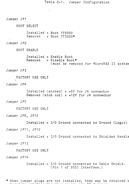
HARDWARE BOOTSTRAP JUMPERS
The enabling or disabling of the hardware bootstrap and the selection of the bootstrap address are coupler parameters that need to be con-figured before the coupler is installed in the computer backplane. The coupler contains a bootstrap PROM that can be enabled or disabled
by jumper JP2. If enabled, the bootstrap address can be changed by
jumper JP1.
NOTES
1. Installation in MicroVAX II systems requires
dis-abling the bootstrap; remove JP2.
2. With JP2 removed, the JP1 jumper has no effect on
coupler operation~
3. If jumper( s) are removed, it is recommended that
they be rotated 90 degrees for storage to prevent loss, i.e., install with one jumper pin inserted over only one pin of the jumper location.
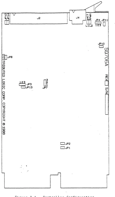
Figure 2-1 illustrates the location of the jumpers. Table 2-1 shows
the jumper position possibilities. The controller is shipped with
jumpers installed with the bootstrap PROM enabled and bootstrap
I
~~~~~IV~---~I!~V~~~
!I
~I
J2I L
J4~M
vlP4 JJ111. W~i _ _ _ _ _ _ _ _ _ _ ---oi i I W r:::::J
0
~JP8
-4 :::0 ~ (JJ C -4 rn o r o G1 ~ ( j ("") o :n 1) n o 1) -< :n H (j') I -I @ ~ <DIfg
I
I
I0
23 1
~'JP3
DJP13 JP7
DJP2
CJJP1
L1L2 ~
JP10 ,---, I...I(JJ
o
'-.Io
m
l> :n rn [image:12.626.114.498.50.705.2]o
(J)...
n
l
Table 2-1. Jumper Configuration
Jumper J P 1
BOOT SELECT
Installed
=
Boot 775000Removed
=
Boot 773000*Jumper JP2
BOOT ENABLE
Installed
=
Enable BootRemoved
=
Disable Boot*(must be removed for MicroVAX II systems)
Jumper J P3
FACTORY USE ONLY
Jumper JP4
Jumper J P7
Installed (etched)
=
+5V for J4 connectorRemoved (etch cut)
=
+12V for J4 connectorFACTORY USE ONLY
Jumper JP8, JP10
Installed
=
Ilo
Ground connected to Ground (Logic)J urn pe r J P 11, J P 1 2
Installed
=
I/O Ground connected to Shielded HandleJumper J P13
FACTORY USE ONLY
Jumper J P14
Installed
=
I/O Ground connected to Cable Shield.(Pin 1 of SCSI Interface.)
[image:13.613.56.500.64.696.2]CONTROLLER INSTALLATION
After the jumpers have been positioned install the controller as follows:
CAUTION
ENSURE ALL POWER IS OFF BEFORE INSTALLING
THE
CON-TROLLER OR CABLES.
DAMAGE TO THE BACKPLANE ASSEMBLY WILL OCCUR IF THE
CONTROLLER IS PLUGGED IN BACKWARDS.
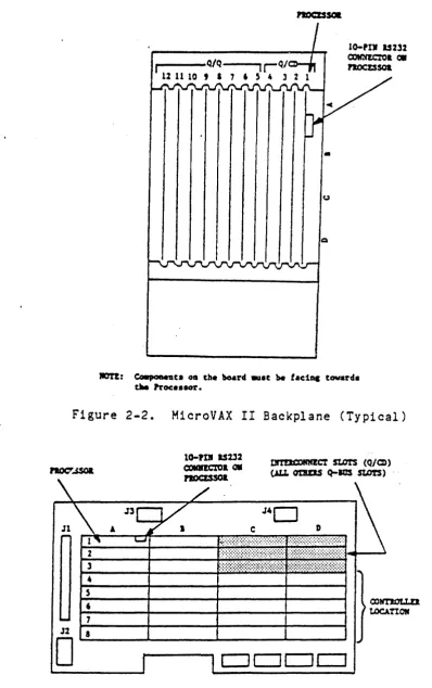
1. Select the backplane location into which the controller is to be
inserted. There are several backplane assemblies available from
DEC and other manufacturers. Figures 2-2 and 2-3 show typical
backplane configurations.
2.
It is important that all option· slots between the processor and the disk controller be filled to ensure that the daisy-chained interrupt (BIAK) and DMA (BDMG) signals be complete to the
con-troller slots. If there must be empty slots between the
control-ler and any option board, the following backplane jumpers must be installed:
FROM
CO X NS
CO X S2
TO
CO X M2 CO X R2
SIGNAL
BIAK1/LO BDMG1/LO
Perform this step if the serial port is· to be connected. the cable from J4 on the controller to the terminal.
Table
1-3
for pinouts and descriptions.Connect Refer to
3. Install one end of the cable into the J2 connector on the
con-troller. ENSURE PIN 1 ON THE CABLE IS MATCHED WITH THE TRIANGLE
ON EACH CONNECTOR AS INDICATED ON FIGURE 2-1.
4. Ensure the controller is oriented with the components facing row
one, the processor, and gently press both sides until the module connectors are firmly seated in the backplane.
5. Connect the other end of the cable to the drive or drives if
daisy-chained,. ~ Ensure the terminator is installed in the last
d r i v e. ;~.
6. Refer to the disk drive manual for' operating instructions, and
•
u
lOTI: eo.,aDeGc. os tbe board .u.c be tae1ac toward.
tM PrOC: •• 8Or.
Figure 2-2. MicroVAX II Backplane (Typical)
DlI!lQ:)RMECT stars (Q/CD)
noc:r...ssoa (J.Lt. cmtEIS Q-IGS stO!S)
J4D
DCJDc:::J
[image:15.615.91.490.55.690.2]7. Power-up the system. Note that there are two green LEDs. The leftmost LED is the POWER LED; the rightmost LED is the ACTIVITY
LED. If the Power LED lights, power to the SCSI bus terminators
has been properly applied; if the Power LED does not light, the
SCSI bus terminators have not received power. If this should
happen, check the power supply on the system or the fuse on the
controller. The user should note that the Power LED will turn ON
if either a SCSI device with power applied is connected to the
controller or power is applied to the controller. This is in
ac-cordance with the SCSI specification, which enables bus term-inator power to be suppl ied by ei ther the SCSI dev ice or host adapter.
8. Upon a good power-up (i.e., the POWER LED lights), the ACTIVITY
LED should turn on for 10 seconds and turn off for 10 seconds. Each 10-second transition of ON/OFF or OFF/ON of the ACTIVITY LED
indicates a successful pass of the controller self tests. The
controller will continue to perform its onboard self tests upon power-up until brought online by the system (i.e., the ACTIVITY
LED will continue to flash on and off every 10 seconds). After
it is brought online, the controller will turn on its ACTIVITY
LED only during read and write activity between the controller and the SCSI device.
9. If an error is encountered at any point during the self tests, a
5-bit binary error code will be flashed on the ACTIVITY LED,
sig-nifying which error has occurred. (See ERROR CODES for details.)
The most significant bit of the error code is flashed first.
A-long flash indicates a binary
"1",
while a short flash indicatesa binary "0." This error code will continue to flash until the
board is either powered down or reinitialized.
10. The system is now ready to operate.
des-SECTION 3
OPERATION
This section covers the operation of the system, including establish-ing communication with the computer, the controller (host adapter), and the drives; bootstrapping for MSCP as well as other emulations; and formatting.
Diagnostics include ZRCFB3, ZRCDA1, and MicroVAX/~I; MDM KDA50-Q. See
Section 4 for details.
Error codes from the error logs and their formats are listed in
Section
5.
INITIATING COMMUNICATION
VIA CONTROLLER SERIAL PORT
In order to bring up communication via the serial port, a terminal
must be connected to the 10-pin connector (J4) located on the
con-troll e r boa rd. S e ria 1 communi cat ion s w ill t h en be gin aut om at i cally
upon power up of the controller or re-boot of the host system. Serial
communications take place at a rate of 9600 baud; therefore, the
ter-minal must be set to both transmit and receive at this rate. The
seri al communi ca ti on protocol is 1 start bi t, 1 stop bi t, 8 da ta bi ts
VIA VIRTUAL TERMINAL
Procedure for Bringing Up the Virtual Terminal Via LSI-11 Wi th Host Adapter Boot Enabled
In order to bring up communication via the virtual terminal, the system console is used as the terminal for serial communication.
The system console must be placed in the ODT (Online Dehugging
Technique) mode. A boot must be initiated by typing on the
sys-tem console either 77775000G or 7777,3000G, depending on which
boot address is selected on the controller (see Section 2 on
hardware jumpers for details on boot address). The system
con-sole will respond with an n*" as a prompt. At this point, the
user can type an "FT" which will bring up the Configuration Menu.
NOTE
In the follow i ng exam pI e s, all ch aract ers unde
r-lined are output by the system; characters not
underlined are input by the user~
EXAMPLE:
If the bootstrap is enabled and the boot address is 175000,
proceed as follows (enter):
~ 77775000G
*
Procedure for Bringing Up the Virtual Terminal Via LSI-11 Wi th Host Adapter Boot Disabled
If the boot on the controller is disabled, communication via the virtual terminal can be brought up by typing
77777
(octal) to the SA address (SA default address=
160336) followed by a carriage return. The user must then type 2000G. The system console will respond with an rr*n as a prompt. The user should then type "FT" to b r i n g up the Co n fig u rat ion Me n u • In the f 011 ow i n g e x am pI e underl ined characters are output by the compute.r:/
NOTE
This procedure will work regardless of whether the boot address of the controller is enabled or dis-abl ed.
EXAMPLE:
!
160334/0 <CR>~ 160336/005400
77777
<CR>~ 2000G
Boot for the device as described below.
The controller not only supports standard DEC devices, but also allows the use of the onboard Configuration Menu. When DU is used, the standard DEC emulation is called. When FT is used, the onboard Configuration Menu is enabled for use through the system console.
*
Enter one of the following: DMO, DPQ, DLO, DRO, MSO, MTO, MUO, DYO, DU, or FT <CR>NOTE
When making a selection, capital letters must be used.
Definitions are as follows:
DM
=
RD06/07 Disk DP=
RP02/03 Disk DL=
RL 0 1 1 0 2 Dis k DR=
RM03/05/80 Disk MS=
TS11 TapeMT
=
TapeMU
=
CTMSCP) Tape DY=
RX02 Floppy Disk DU=
DU ernul ati onProcedure to Bring Up the Virtual Terminal Via MICRO-VAX II
In order to bring up communication via the virtual terminal, the
system console is used as the terminal for serial communication.
Note that the bootstrap PROM must be disabled. (See Section 2 for jumper placement.)
Upon powering up the MicroVAX II, the user must set up the
MicroVAX II 1/0 map via the system console, type
3FFF
hex to theSA address (SA default address
=
160336) and start executing codeat location 200 hex. All this can be done by the user as shown
below. After executing this procedure, the Configuration Menu
comes upon the system console. Note that the bootstrap PROM must
be disabled.
EXAMPLE:
»>D/P/L 20088004 800000Q1 <CR> <--Setup MicroVAX II I/O Map
»>D/P/W 20001F40 20 <CR>
»>D/P/W xxxxxxxx
3FFF
<CR>'AD 0 D ()~Af
2.22S 200 <CR>
<--Setup MicroVAX II I/O Map
<--Deposit the
3FFF
hex in SAad-dress. The values of xxxxxxxx
are hex values of the control-ler address of the SA register
and are listed in Table
3-1.
<--Start executing code at 200
10-\.0 v .. " \..0 "" •
(At this point the Configuration Menu should appear.)
NOTE
When a GPX (Graphics Work Station) is used, enter
CONFIGURATION MENU
Upon entering the controller's onboard Configuration Menu, the first
prompt to appear is:
ARE YOU USING A (P)RINTER OR (C)RT?
Type a flP" if a printer terminal
attached, and a carriage return,
appear as follows:
CONFIGURATION MENU
1 - STANDARD DIAGNOSTICS
is being used or a ncn if a CRT is
then the Configuration Menu will
2 - HOST Q-BUS MEMORY DMA TEST
3 - DISPLAY CONTROLLER CHARACTERISTICS
4 - SET CONTROLLER CHARACTERISTICS
5 - SCSI DIRECT COMMAND
6 - FORMAT SCSI DRIVE
7 -
SCSI UNIT MAPPING.ENTER A SELECTION:
Any of the seven selections may be entered at the prompt simply by
typing the number that c~rresponds to the desired selection followed
by a carriage return.
NOTE
A CTRL C (AC) entered during any of the selections will return to the Configuration Menu.
STANDARD DIAGNOSTICS
Selection 1 of the Configuration Menu enables the controller to run
its onboard diagnostics. Each time a diagnostic test is successfully
passed, a "." will be printed onto the screen. It takes approximately
10 seconds for the controller to make one pass through all the
diag-nostic tests. The controller will continue to loop on the diagnostic
tests until a CTRL C CAC) is typed on the terminal. (Notice that the
controller does not respond immediately to the AC when in the virtual
terminal mode. It takes several seconds for the controller to respond, so please be patient.)
Upon recognizing the AC, the controller will return to the
Configura-tion Menu. If an error is encountered during the execution of a
diag-nostic test, an "E" will be printed onto the sC'reen and the onboard
LED will flash the appropriate error code. (See documentation on
error code flashing for details.) The controller will conduct a loop
on error process until either a AC is detected or power on reset is
HOST MEMORY DMA TEST
Selection 2 of the Configuration Menu enables the controller to con-duct DMA transfers to and from the host system.
CAUTION
THIS TEST WILL WRITE ALL OF HOST MEMORY -- THERE-FORE, ANYTHING RESIDING IN HOST MEMORY AT THE TIME THIS TEST IS CONDUCTED WILL BE OVERWRI~TEN!I
T his t est v e r i fie s t hat d a taw r itt e n t 0 and rea d~'" from the h 0 s t i s val id to ensure that operations between the host and the controller are functioning properly. When using this selection, make sure the host system has finished ini tial izing the mapping registers. Other-wise, the test will report memory size equal to ~ero.
NOTE
This test will not be executed if operating in virtual terminal mode.
Upon· sel ecti ng the HOST MEMORY DMA TEST, the controller will go out and size the host memory. The controller will then begin a series of DMA tests to ensure host-controller DMA communications are functional.
The following will be disabled upon a good pass of the DMA test.
(CTRL-C ABO~TS BACK TO MAIN MENU)
SIZING HOST MEMORY ...
MEMORY SIZE
=
XXXX HEX (IN KBYTES) TESTING HOST DMA.~ .... TESTING DMA ON ODD, EVEN ADDRESSES W/EVEN BYTE COUNT .•• TESTING READ REVERSE
••• TESTING ONE WORD DMA
••• TESTING ONE BYTE DMA (ALSO TESTS BYTE SWAP) DMA IS OPERATIONAL OVER ENTIRE HOST MEMORY.
The test will continue to run until a CTRL-C is typed on the console. If the test ever detects an error, an error message will be displayed on the console. The following is a list of all possible errors.
>
NON-EXISTENT MEMORY ERRORThis error indicates that the controller write a nonaccessable memory location. error, the following message is displayed.
DMA FAILED DUE TO NON-EXISTENT MEMORY
attempted to read or When receiving this
>
DATA MISCOMPARE ERRORThis error indicates that the controller detected a data
miscom-pare error (i.e. the data written and read did not compare).
When receiving this error, the following message is displayed.
DMA FAILED DUE TO DATA MIS-COMPARE
••. AT HOST ADDRESS BLOCK LOCATION XXXX HEX
DATA RECEIVED
=
XX HEX DATA EXPECTED=
XX HEX>
Q-BUS PARITY ERRORThis error indicates that the controller detected a Q-bus parity
error while performing a DMA transfer. When receiving this
error, the following message is displayed.
DMA failed due to a QBUS Parity Error ..• AT HOST ADDRESS BLOCK LOCATION XXXX HEX
>
DMAC PARITY ERRORThis error indicates that the controller detected an internal
parity error when reading the controller buffer RAM. When
re-ceiving this error, the following message is displayed.
DMA FAILED DUE TO A DMAC PARITY ERROR
Upon receIvIng an error, the test will also print an "E" on the
console and flash an error code on the activity LED. The test will
then attempt to restart the test. On occasion, the test will be
unable to restart or be aborted via a CTRL-C; therefore a power on
DISPLAY CONTROLLER CHARACTERISTICS
Selection 3 of the Configuration Menu allows the user to display on
the terminal the current controller characteristics as determined by
what is currently set in the controller's NOVRAM. Selection 3
displays the following:
DISPLAY CONTROLLER CHARACTERISTICS
IP/SAADDRESS (IN OCTAL':
DWELL COUNT '( COUNT
*
BOO NSEC=
DWELL TIME)!BURST SIZE (# OF WORDS):
INTERRUPT PRIORITY:
** ** ** PRESS <CR> TO CONTINUE ** ** **
[XXXXXX] [XXX] [XXX]
[XX]
As seen above, the IP/SA address, the dwell time and burst size for
DMAs, and the controller's interrupt priority to the host are
dis-played. The X's in the table above represent the current value of
each controller characteristic. The address is given in octal value
and all the other values are decimal. After displaying the controller
characteristics, a carriage return, <CR>, will display the
Configura-tion ,Menu again.
Below is a list of the default values of the controller configuration
characteristics:
IP/SA ADDRESS (IN OCTAL):
DWELL COUNT (COUNT
*
BOO NSEC=
DWELL TIME):BURST SIZE (# OF WORDS):
INTERRUPT PRIORITY:
DEFAULT VALUE
[160334 ]
[02]
COB]
SET CONTROLLER CHARACTERISTICS
Selection 4 of the ,Configuration Menu allows the user to set the
controller characteristics (i.e., set up the NOVRAM). Selection 4
displays the following:
SET CONTROLLER CHARACTERISTICS
[ ] =
CURRENT CONFIGURATION, <CR>=
DEFAULTS TO CURRENT SETTINGIP/SA ADDRESS: DWELL COUNT:
(COUNT *800 NSEC
=
DWELL TIME)BURST SIZE (# OF WORDS):
INTERRUPT PRIORITY:
SAVE NEW CONFIGURATION (Y/N)?
[XXxxxxJ [XXXL ~)
[XXX] [XX]
{USER RESPONSE} {USER RESPONSE}
{USER RESPONSE} {USER RESPONSE}
In order to set the controller characteristics, the user is prompted
for all the information. The user is first prompted for the IP/SA
address. The current setting is displayed alpng with the "IP/SA
Address" message. A prompt then appears and waits for user response.
The ~ser response in the above table is indicated by the message
"{user response}." The user now has the option of changing the
cur-rent IP/SA address. He can do this simply by typing a new address (in
octal) at the prompt followed by a carriage return. If the user does
not wish to change the address, he need simply type a carriage return
and the address will remain unchanged. In either case, the user will
then be prompted for the dwell time. He will again have the same
option as before; he can either change the value or leave it at its
current setting. He will then be prompted for the next piece of
in-formation, and this process will continue until all the information on
the controller characteristics has been prompted for. The controller
will then prompt the user as to whether or not the new configuration
is to be saved in the controller's NOVRAM. If the user chooses not to
save the new configuration, the controller will simply display a
mes-'sage saying that the new configuration was not saved. A <CR> at this
time will simply take the user back to the Configuration Menu. If the
user chooses to save the new configuration, the controller will
re-spond with the following:
NEW CONFIGURATION SAVED IN NOVRAM •..
REBOOT SYSTEM TO CONFIGURE CONTROLLER HARDWARE!
The host system only needs to be rebooted if the IP/SA address was
changed; otherwise, the user need only type a <CR> to go back to the
Configuration Menu.
During the prompting of the controller characteristics, the controller
will respond with an "Invalid Response" message if the user response
is considered invalid. The controller expects all user responses to
be in decimal except for the IP/SA address which it expects to see in
octal (for appropriate octal IP/SA addresses see the options listed
Below are lists of valid options for each of the controller configura-tion characteristics.
IP/SA ADDRESS (IN OCTAL):
SUGGESTED ADDRESSES:
DWELL COUNT:
(COUNT
*
800 NSEC=
DWELL TIME)BURST SIZE:
INTERRUPT PRIORITY:
How To Find Current Address
[160000 - 177774J
[i72150,i60334,i60340,16034 4 ,
160354,160360j 160374J
[1-63J
[4-7J
In case the user ever changes the controller slave address (IP/SA address) and forgets what value he set it to, the following steps should be taken:
FOR LSI=11 SYSTEM:
1. Enable the boot address on the controller and make sure
no other controller is using the same boot address (see details on hardware jumpers).
CAUTION
MAKE SURE BOARD IS POWERED DOWN BEFORE
CHANGING JUMPERS!
2. Power up the board, and get into ODT mode. Conduct a
boot by typing on the system console either
77775000G
or
77773000G,
depending on what boot address the userhas enabled. (See section on INITIATING COMMUNICATION
for details on boot procedure~)
3.
Wait for the"*"
prompt.4. Halt the host system processor and look at address
location
o.
Location zero should contain the IP/SAaddress.
How to examine address
a
using aDT:FOR MICRO-VAX II SYSTEM:
i . Conduct a power on reset on the board (i.e., power down the board and power it 'back up).
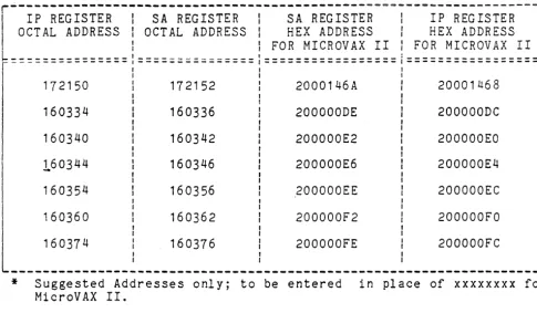
2. Check all the possible SA addresses that can be
select-ed on the controller via the system console. (See Table 3-1 for listing of suggested IP and SA addresses, refer to hex address only.)
How to examipe addresses on MicroVAX II:
222E/P/W xxxxxxxx <CR>
".
< ---- Allow,s user to exam i ne
loca~ion xxxxxxxx, a hex address from Table 3-1.
If required to check the range 160000Q-17774Q, a
suggested method is to start examining at location
1600000 as shown above (corresponding hex address for
MicroVAX II is 20000000 calculated as shown below Table
3-1. After examining the first address, the user can
continue checking subsequent addresses by simply typing the following:
222 E <CR> <---- allows the user to examine subsequent
hex addresses.
3.
Once the user finds the address he suspects is thecon-troller slave address, he should deposit a 0 in the
corresponding IP address. If the controller responds
with a OBOOH in the SA address, then the correct slave
address has been found. Deposit a 0 in the IP address
as shown below:
How to deposit a 0 on MicroVAX II:
222D/P/W xxxxxxxx 0 <CR>
<----
Allows user to deposit ao
at location xxxxxxxx,a hex address from Table
3 -1 •
4. If the slave address does not respond with OBOOH, then
Table 3-1. IP and SA Hex Addresses
*
r---~~---~---l . IP REGISTER I SA REGISTER I SA REGISTER I IP REGISTER
OCT AL ADDRESS I OCTAL ADDRESS I HEX ADDRESS I HEX ADDRESS I
I I FOR MICROVAX II I FOR MICROVAX II
I
~~~=============,====~===~~~====l=================:=================~
I I
*
, I
172150 172152 2000146A 20001468
I
160334
160340
160344
160354
160336
160342
160346
160356
200000DE
200000E2
200000E6
200000EE
Suggested Addresses only; to be entered MicroVAX II.
200000DC
200000EO
200000E4
200000EC
I
in place of xxxxxxxx for
For addresses other than the above (a~dress range 1600000-177740) perform the following to calculate hex address for MicroVAX II:
A. Convert the 13 least significant bits of the address in octal to hexadecimal.
B. Add 200000000.
For example, if the octal address is 177740, the hex value is obtained as follows:
A. 177774 octal with 13 LS bits
=
17774, converted to hex=
1 FFC.
[image:28.624.60.545.114.397.2]SCSI DIRECT COMMAND
Selection 5 of the ~onfiguration Menu allows the user to input and
execute SCSI commands. At this point, all user responses must be
input in hex. All of the controller's responses will be displayed in
hex.
Upon entering the SCSI DIRECT COMMAND mode the user is prompted for
the SCSI device node number, logical unit number, and number of bytes
in the command descriptor .block (CDB). The user is then asked to
input the SCSI command descriptor block CCDB) one' b~te at a time. The
user is prompted as follows:
ENTER IF OF COMMAND BYTES: {USER RESPONSE}
ENTER SCSI COMMAND DESCRIPTOR BLOCK (CDB):
[E.G., FOR A FORMAT COMMAND, LUN
=
00]BYTE flO
=
04BYTE #1
=
00BYTE #2
=
00BYTE fl3
=
00BYTE #4
=
00BYTE #5
=
00DATA TRANSFERS LIMITED TO 1 SECTOR [512 BYTES]
ENTER COMMAND BYTE #0
=
{USER RESPONSE}ENTER COMMAND BYTE fl1
=
{USER RESPONSE}ENTER COMMAND BYTE #2
=
{USER RESPONSE}ENTER COMMAND BYTE #3
=
{USER RESPONSE}ENTER COMMAND BYTE 114
=
{USER RESPONSE}ENTER COMMAND BYTE fl5
=
{USER RESPONSE}In order to input the command descriptor block, the user need simply
type, in hex, each command byte when prompted for. An example of a
FORMAT command is given as part of the prompt message to demonstrate
how the user is to enter the command properly. The prompting of the
command bytes will continue until the specified number of command
bytes have been received. Note that all user responses above are
indicated by "{user response}." If the user ever inputs an invalid
response, the controller will respond with an tt** Invalid Setting"
message. The user will then again be prompted for the appropriate
information. Also, the user must note that all data transfer commands
are limited to 512 bytes. An attempt to transfer more than 512 bytes
Upon recelvlng the command descriptor block, the controller will
dis-play the c;ommand bytes entered. The user is then prompted as to
whether or not the command bytes displayed are correct. If the
com-mand bytes are correct, the user need simply type nyu for yes and the
controller will continue on wi t h i ts next prompt. If the command
bytes are incorrect, the user must then type an "N" for no. At this
point the controller will respond with a second prompt asking if the
user wishes to go back to the Configuration Menu. If the user
re-sponds wi th a "Y" for yes: the controller .. will take him back to the
Configuration Menu, otherwise an "N" for no will take the user back to reenter a SCSI command descriptor block (COB).
Once the user has input a command correctly, the controller will
prompt him as to whether or not he wishes to send data out during the
ex e cut ion 0 f the com man d • Th e use r nee don 1 y sen d d a t a o u t i f the
current command to be executed sends data to the target; otherwise,
the user should respond to the prompt with an "N" for no. If data
does need to be sent out to the SCSI device, the user should type a flY" for yes, at which point the controller will prompt him for the
number of data bytes to be entered. The user will then be asked to
input the data bytes one byte at a time.
NOTE
The maximum number of data bytes that can be
en-tered is 512 bytes.
ENTER # OF DATA BYTES: {USER RESPONSE}
DATA BYTE #0000 = {USER RESPONSE}
DATA BYTE 110001 = {USER RESPONSE}
DATA BYTE fFOO02 = {USER RESPONSE}
DATA BYTE 110003 = {USER RESPONSE}
DATA BYTE 110004 = {USER RESPONSE}
DATA BYTE 110005 = {USER RESPONSE}
DATA BYTE 110006
=
{USER RESPONSE}DATA BYTE 110007 = {USER RESPONSE}
DATA BYTE 110008 = {USER RESPONSE}
DATA BYTE IFOO09
=
{USER RESPONSE}DATA BYTE /FOOOA = {USER RESPONSE}
In order to inputu~ tQe data bytes, the user need simply type, in hex,
each data byte when prompted for. The prompting of the data bytes
will continue until --the specified number of data bytes have been
re-ceived. Once all of the data has been input, the controller will
dis-play the data bytes. It will then prompt the user as to whether or
Upon inputting correct data or specifying that no data need be sent
out, the user will be prompted as to whether or not the command
entered is to be executed. The user is prompted as follows:
CAUTION
COMMANDS WILL BE EXECUTED AS ENTERED.
DATA ON THE DRIVE MAY BE OVERWRITTEN.
EXECUTE COMMAND (YIN)?
> ~
CURRENT
The caution indicates that the SCSI device will reG~ive the command as
entered by the user; therefore, the user should" ehsure that the
com-mand is correct before executing. Also, in case the user issues a
write command, he should be aware that any data on the SCSI device at
the location of the wri te command will be overwri tten. If the user
chooses not to execute the SCSI command, he should type an "Nfl at which point the controller will take him back to the Configuration
Menu. If the user chooses to execute the command, he need simply type
a "Y. If At this pOint the controller will display the following
mes-sage:
EXECUTING SCSI COMMAND
Upon completion of the command a number of different messages may
ap-pear. The different messages and their meanings are as defined below:
>
SCSI COMMAND COMPLETED WITH NO ERRORSThis message indicates that the command was successful and no
errors occurred during its execution. If this message is
dis-played after executing a read command, the controller will auto-matically display the read data from the SCSI device.
>
CHECK CONDITION ON SCSI COMMANDThis message indicates that a check condition occurred during the
execution of the command. The controller will automatically
re-quest sense data from the SCSI device and display the sense data following this message.
>
SCSI BUS PARITY ERRORThis message indicates that a SCSI bus parity error was detected during the execution of the command and subsequent retries of the command also produced parity errors.
>
SCSI BUS PARITY ERRORRETRY WAS SUCCESSFUL
>
QBUS PARITY ERRORThis message indicates that a QBUS parity error occurred during an access of QBUS memory.
>
CONTROLLER PARITY ERROR DURING ACCESS OF DRAMThis message indicates that a controller parity error occurred
during ~n ~~~~ss of the controller's DynDmic RAM.
>
SCSI BUS RESET OCCURRED DURING COMMAND EXECUTIONThis message indicates that a SCSI bus reset occurred during the
execution of the command; therefore, the command was not
cam-pI eted.
>
SCSI DEVICE NOT RESPONDING
This message indicates that the SCSI device is not responding to the command issued.
>
TRANSFER TRUNCATED TO SINGLE SECTOR {512 BYTES}This message indicates that a multi-sector data transfer command
was attempted. The command was therefore truncated to a single
sector command. If this message is displayed after a read
com-mand, only a single sector of data will be displayed.
>
COMMAND TIMEOUTThis message indicates the requested command took over an hour without any activity on the SCSI bus.
Upon the completion of the command, the controller will prompt the user with the following:
ISSUE ANOTHER SCSI COMMAND
(YIN)?
At this point the user can either issue another SCSI command simply by
typing a "Y" for yes, or he can go back to the Configuration Menu by
FORMAT SCSI DRIVE
Selection 6 of the Configuration Menu allows the user to format a SCSI drive. Upon entering FORMAT SCSI DRIVE mode, the user is prompted for all the SCSI drive information needed in order to format the drive. The prompting is as follows:
FORMAT SCSI DRIVE
NODE
H
OF DRIVE TO FORMAT'(0-7): {USER, RESPONSE}LOGICAL UNIT NUMBER (LUN) OF DRIVE TO FORMAT (Cf-3')': {USER RESPONSE}
DRIVE FORMAT INTERLEAVE (0-7): {USER RESPONSE}
FORMAT USING PRIMARY DEFECT LIST ONLY (YIN)?
The user is first prompted for the SCSI node of the drive to be for-matted (node selection varies between 0 and 7). The user need simply respond by typing a value between 0 and 7 followed by a <CR). (Note that all user responses above are indicated by "{user response}".)
The ,user is next prompted for the Logical Unit Number (LUN) of the drive to be formatted (LUN selection ranges from 0 through 3). The user need simply respond.by typing a value between 0 and 3 followed by
a <CR).
The user is next prompted for the drive format interleave. Inter-leaving is a technique of assigning successive addresses to sectors which are physically separated on the disk, in order to reduce access time. A 3 to 1 interleave requires three rotations of the disk to transfer one track. The range for interleaving on the host adapter is from 0 to 7, where an interleave of 0 allows the SCSI drive to set its own defaul t interleave and 1 through 7 allows a 1 to 1 through 7 to 1
interleave, respectively. To set the interleave, the 'user need simply type a value between 0 and 7 followed by a <CR).
The user is prompted if only the primary defect list will be used as the flaw map when formatting. Responding with a nyn (Yes) will return the disk to the condition as originally shipped. No flaws found and reassigned since the original defect list will be added. Responding with an "N" (No) will include flaws found and reassigned in the growth list. Depending on the response, one of the following messages will be displayed:
PRIMARY DEFECT LIST HAS BEEN SELECTED
OR
After inputting all the requested information, the controller will respond with the following message:
CAUTION
ALL DATA WILL BE LOST TO THE SELECTED DRIVE.
CONTINUE WITH FORMAT (YIN)?
The caution serves to warn the user that the data on the drive will be
lost once the format command has taken place. Therefore, if the user
does not wish to destroy- the data on the disk, he can simply reply with an "N" at the prompt followed by a <CR) and the controller will
take him back to the Configuration Menu. If the user wishes to
con-tinue with the format, he then need simply type a "Y" at the prompt followed by a <CR).
Once the formatting has begun, the controller will print the following message:
FORMATTING SELECTED DRIVE
This message will remain until the drive has completed the format com-mand.
At this point, if the SCSI drive formats with no errors, the
control-ler will print a "Completed" message. Otherwise, if any errors occur,
one of the SCSI DIRECT COMMAND error messages will be displayed. (See
SCSI UNIT MAPPING
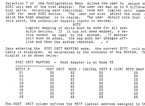
Selection 7 of the Configuration Menu allows the user to select the
SCSI unit map of the host adapter. The user can map up to 8 different
host units, -selec~ing each individual node and logical unit number
(LUN) for each SCSI device. The user can also select the node at
which the host adapter is to reside. The user should note that at
this point, the controller expects inputs in decimal. NOTE
Logical mapping of units must be done for all
pos-sible devices. If it has not been mapped, a
de-vice cannot be .used by the system. ~ Tf another
unit must be added, the map must be/ qhanged
off-line and then the sy stem rebooted. ~ ,',.(
Upon entering the SCSI UNIT MAPPING mode, the current SC~I unit map
table is displayed, as de~ermined by the contents of the NOVRAM. The
display is as shown below:
SCSI UNIT MAPPING Host Adapter is at Node XX
---~
SETUP IF HOST UNIT NODE / LOGICAL UNIT II (LUN) BYTE SWAP
01 XX XX XX XX
02 XX XX XX XX
03 XX XX XX XX
04 XX XX XX XX
05 XX XX XX XX
06 XX XX
xx
XX07
XX
XX vv XXAA
08 XX XX
xx
XXThe HOST UNIT column defines the MSr.P lo~ical address assigned to the
device node and logical unit II (LUN). For example, Host TTnit 00 would
be recognized by VMS as DUAO. DUBO, etc., de-pending on the adapter
address.' Addi tional logical dev ices connected to the adapter on the
SCSI bus require a successive Host Logical Unit number, i.e., DUA1,
DUA2t (DUB1, DUB2) etc. be assigned. The Node column ,defines the SCSI
device (intelligent peripheral or controller) node. address. The
LOGICAL UNIT , (LUN) column defines the SCSI address fro the
peripheral attached ·to the mapped device NODE. Note that in the
majority of cases, the LUN II will always be zero; the vast majority of
peripherals connected to a node contain a built in controller. The
master controller/peripheral with attached slave peripherals without
controllers is rare.
The constraining factor is that there can never be more than eight (8)
nodes on an SCSI bus (including the host adapter). The maximum number
of peripheral device nodes and LUN's is defined by the MSCP driver.
not the adapter, for the particular device (typically four for MSCP
disk drives).
As seen above, the SCSI unit map displays the HOST (logical) lJNTT, the
peripheral device NODE / LOGICAL UNIT # (LUN), and BYTE SWAP
configuration for 8 different setups available on the Host Adapter.
In addition it specifies the Node that the Host Adapter occupies. The
xx's in the table above represent the current configuration numbers
for each setup. The default SCSI unit set at the factory is shown on
the next page, followed by an example of the SCSI unit map for adding
[image:35.626.75.580.62.430.2]SCSI UNIT MAPPING Host Adapter is at Node 07
---SETUP Ii HOST UNIT NODE / LOGICAL UNIT t! (LUN)
01 00 00 00
02 No current setup 03 No current setup 04 No current setup 05 No current setup 06 No current setup
07 No ""'1...,,,..,...,,,,,,,4-
-
_..
,.-"' .... 4 4 <;;;41',.-"' h:)C'l"utJ
08 No current setup
Example SCSI UNIT MAP for a three, intelligent peripheral system:
SCSI UNIT MAPPING Host Adapter is at Node 07
SETUP IF HOST UNIT NODE / LOGICAL UNIT t! (LUN)
01 00 00 00
02 02 01 00
03 02 02 00
The default setting of the host adapter does not setup the last seven available SCSI units. As seen above, when a SCSI unit has not been setup, the "No current setup" message will appear.
Following the display of the SCSI unit map,· a menu of the available options for SCSI UNIT MAPPING mode is displayed.
o -
RETURN TO CONFIGURATION MENU 1 - CHANGE UNIT MAPPING2 - CHANGE HO~T ADApTER NODE 3 - SAVE UNIT MAPPING IN NOV RAM 4 - RESTORE DEFAULT UNIT MAPPING
ENT~R A SELECTION:
In order to choose an option, the user need simply type the number of the option he wishes to oerform followed by a <CR).
OPTiON 0 will simply return the user to the Configuration Menu.
OPTION 1 will allow the user to change any of the current setups on the SCSI unit map. Upon entering this option, the user will be prompted for the setup # he wishes to change. The user need simply type the number of the setup he wishes to modify at the prompt follow-ed by a <CR). At this point, if the setup the user wishes to modify currently occupies a valid setup (i.e., the "No current setup" is
Nor
displayed), he will be prompted as to whether or not he wishes to remove the setup. If the user chooses to remove the setup by typing a "Y" at the orompt, the SCSI unit map will be redisplayed and the setup removed will display .. the "No current setup" messa~e. If the user chooses not to remove the setup by typing an "N" at"the prompt, he will then be prompted for the new host unit, node, and lo~ical unit number he wishes to set. If the setup the user wishes to modify has no valid setup (i.e., the "No current setup" message is displayed), he will simply be prompted for the new setup consisting of the host unit, node, and logical unit number. In any case, at the completion of the prompting, the SCSI unit map will be redisplayed with the modifica-tions made by the user.OPTION 3 will allOW the user to save the currently displayed SCSI unit
map in the NOVRAM. This will allow the oarticular map saved to remain
as part of the confi~uration of the host adapter even when the board
has no pow~r applied. The map will be preserved for the life of the
NOVRAM or until another map is saved in the NOVRAM. In order to save
the map in the NOVRAM of the host adapter, the following specification
must be met by the SCSI unit map.
The following specifications exclude those setups which are not valid.
1. All setups must occupy unique host unit numbers.
2. All setups must occupy a unique combination of node and
logical unit number.
3.
No setup can occupy the same node as the host adapter.Unless the above specifications are me~, t.he host adapter will not
allow the SCSI unit map to be saved in the NOVRAM. If the ~CSI map is
not allowed to be saved, the following'message will be displayed:
SCSI UNIT MAP NOT SAvED IN NuVRAM DUE
TU
OVERLAPP1NGOF HOST UNIT NUMBERS OR NODE/LOGICAL UNIt NUMBERS.
If the above specifications are met, the controller will then display
a message saying that the map was saved in the NOVRAM. A (eR) at this
point will redisplay the SCSI unit map.
OPTION 4 will allow the user to restore the ~efault SCSI 11nit map as
set by the factory. Upon entering this option, the user is prompted
as to whether or not he wishes to save the default mapping in th~
NOVRAM. If he chooses to save the mapping in the NOVRAM, he need
simply type a "Y" at the prompt followed by a <CR>
at
,which point thedefault map will be saved and redisplayed. If the user chooses not to
save the map in the NOVRAM, he need simply type an "N" at the prompt,
SECTION 4
DIAGNOSTICS
Two DEC RC25 diagnostics may be used to test the controller. They are ZRCFB3, Front End Test, and ZRCDA1, Disk Exerciser. MicroVAX II, MDM KDA50-Q, diagnostics are also included.
SETUP AND SELF TEST
Install the controller as descri bed in Secti on 2. Appl Y power to the system, and verify that both green LEDs light. Install the XXDP+ diagnostic floppy in the floppy drive and boot the system.
When booting is completed, the XXDP+ sign-on will appear:
XXDP-SM SMALL MONITOR VERSION 2 BOOT FROM DYO
28KW MEMORY ·UNIBUS SYSTEM
RESTART ADDR: 152010.
THIS IS XXDP-SM TYPE "H" OR "H/L" FOR HELP
FRONT END TEST - ZRCFB3
The controller will only support tests 1-8 which must be selected by the user. These tests will bring the controller through initializa-tion several times and do extensi ve checks on the DMA capa bil i ty.
Once the prompt ". n has appeared, type the following command I ine to
start ZRCFB3 diagnostic:
• R Z RCFB3
The system will echo the filename to let the user know that the file is being loaded •
• R ZRCFB3 ZRCFB3.BIN
When the diagnostic has been loaded, the diagnostic startup message will appear on the user's console.
DRSSM-FO CZRCF-A-O
RC25 FRONT END/HOST DIAGNOSTIC UNIT IS AZTEC RC25 PLATTER RSTRT ADR 145676
DR)
The diagnostic can be started by typing the following command line:
DR)START/TEST:1-8<CR)
The above command line instructs the diagnostic supervisor to start the test but initiate only tests 1 through 8. The supervisor will then prompt the user for hardware or software changes.
C HANG E HW (L) ?
The diagnostic must be informed of the hardware parameters of the sys-tem under test. Enter the following information.
CHANGE HW (L) ? Y<CR)
Enter the number of controllers that are being tested.
I! UNITS (D) ?,':-1~·CR>
" ,
The platter address is the unit number of the disk drive under test. Since the controller does not support the tests which require a disk, this question is not. appropriate but must be answered to start the diagnostic. Once the hardware questions are answered, the supervisor will prompt for software changes.
CHAN G E SW (L) ?
The software question can be answered NO because the controller does not support the tests which require a disk drive.
CHANGE SW (L) ? N<CR>
The diagnostic will print each test as it runs and will inform the user of any errors that occur.
TESTING UNIT II:
o
IP_REGISTER:172150 TEST 1TEST 2 TEST 3 TEST 4 TEST 5 'TEST 6
TEST 7 TEST 8
REGISTER EXISTENCE TEST
STEP 1 READ/WRITE POWERUP DIAGNOSTICS DIAGNOSTIC WRAP TEST
VECTOR AND BR LEVEL TEST
STEP
1-3
READ/WRITE DIAGNOSTIC PURGE POLL TESTSMALL RING TEST LARGE RING TEST
PLATTER II: 0
When the diagnostic has completed all the tests, the end of pass message will be printed and the diagnostic will be restarted.
DZ RCF EOP 1