Volume 9, Number 1, pp. 39–49.http://www.scpe.org c 2008 SCPE
APP: AGENT PLANNING PACKAGE∗
SA ˇSA TO ˇSI ´C†, MILO ˇS RADOVANOVI ´C†,ANDMIRJANA IVANOVI ´C†
Abstract. Nowadays, a large number of planning systems exist. The majority of them are either applicable only to specific domains (domain dependent) or support only plan generation, but not plan execution and supervision. This paper presents Agent Planning Package (APP), a new domain independent planner which facilitates the creation of intelligent agents. Through the use of APP, agents can generate plans within their operating environment, as well as execute them and supervise the execution. Furthermore, APP supports online changes to the planning problem and domain, as well as creation of multiple plans and plans which contain alternative paths of execution.
1. Introduction. Modern mainstream application development tools offer many features which simplify and quicken the development process. Developers can easily create and incorporate databases into their projects, design user inter-faces, enable network communication of programs, use extensive libraries which implement standard data structures and algorithms, etc. Development tools also support the break-down of larger problems into smaller ones, and merging of small problems into larger, but these operations have to be performed manually by the programmer. None of the standard development tools offersautomaticcombining of small functional parts, in the sense of the tool itself generating their order of execution to solve a larger problem. Furthermore, the tools provide little control of pre- and post-conditions for the execution of a part of a program, except for debugging purposes, which again requires the problem solution to be specified by hand. The craft of manual problem solving is one of the most demanding and error-prone parts of the application development cycle.
On the other hand,planning systemssolve complex problems by combining atomic actions which can be performed. They use a declarative description of actions and the goal, based on which they create a plan, i.e. a sequence of actions which need to be executed in order to take the system from the initial state to the state with the desired properties.
When specifying actions one needs to specify their parameters, the preconditions which must hold before the action can be executed, and the effects of the actions. A large number of planning systems also support specifying of the cost of action execution, and the probabilities that actions will be performed successfully.
Although the integration of concepts from planning systems into mainstream application development tools seems far away, the coupling of automatic planning withagent development systemsis a reality. This paper presents Agent Planning Package (APP), a new domain independent planner which facilitates the creation of intelligent agents. Through use of APP, agents can generate plans within their operating environment, as well as execute them and supervise the execution. Furthermore, APP supports online changes to the planning problem and domain, as well as creation of multiple plans and plans which contain alternative paths of execution. The main purpose of APP is not to present a new deliberative agent architecture (although it may be possible to treat it as such), but rather to enable the extension of existing architectures with planning capability.
The rest of the paper is organized as follows. Related work and major existing planning systems are reviewed in Section 2. APP is introduced in Section 3, through a discussion of its basic anatomy and the plan creation process. Sec-tion 4 introduces a simple logistic domain as a working example that will be used to illustrate APP’s features throughout the paper. Section 5 describes the APP planning cycle in more detail, focusing on the agents’ needs and point of view. Several possibilities for implementation of a logistic agent which utilizes APP are given in Section 6. Section 7 summa-rizes experimental results which show that APP is among the medium-powered planners in terms of speed, and among the most efficient in terms of generating the shortest existing plan if one exists. Finally, Section 8 concludes and outlines the directions for future work.
2. Related Work. Research on planning systems (more precisely, automated problem solving) started in the late 1950s. One of the first programs in this field was GPS (General Problem Solver) by Newell, Shaw and Simon [18]. In 1971, Fikes and Nillson developed the STRIPS (STanford Research Institute Problem Solver) formalism [8], which was the basis for most research in the field until Pednault presented ADL (Action Description Language), mixing the STRIPS approach with the situation calculus [19]. The ADL formalism provided inspiration to many researchers, and soon other formalisms like UCPOP and UMCP emerged. In 1998, PDDL (Planning Domain Definition Language) was introduced [15], attempting to unify the most important aspects of all prior formalisms. PDDL 2.1 added the possibility to specify durations of actions, and integrated the systems for planning and scheduling [9]. In 2002, this version was
∗This work was supported by the Serbian Ministry of Science and Environmental Protection.
†University of Novi Sad, Faculty of Science, Department of Mathematics and Informatics, Trg D. Obradovi´ca 4, 21000 Novi Sad, Serbia, {sashat,radacha,mira}@im.ns.ac.yu.
Agent A Agent B Agent C
Agent Environment
Instances of planner
Agent A Agent B Agent C
Agent Environment
Instances of planner
Planning problems
Planning domain
Planning instance
Data manipulation
Plan execution and monitoring Plan search
Plan validation and verification
Instance of Planner
Generated plans Planning problems
Planning domain
Planning instance
Data manipulation
Plan execution and monitoring Plan search
Plan validation and verification
Instance of Planner
Generated plans
(a) (b)
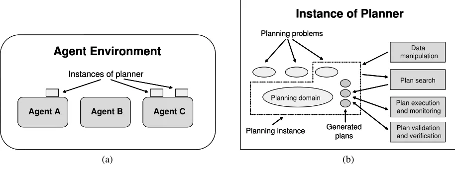
FIG. 3.1.Structure of a multi-agent environment in which agents utilize APP
further extended to PDDL 2.2 by introducing derived predicates and timed initial literals [7]. Year 2005 witnessed the introduction of PDDL 3.0, which enabled the definition of strong and soft constraints on plan trajectories, as well as strong and soft problem goals [10].
In parallel with the development of planning formalisms, planning systems based on them were being written. Some of the well known systems include SHOP [17, 16], GraphPlan [4], STAN [14], FF [12], HSP [5], SAPA [6] and AltAlt [20]. 3. The Agent Planning Package. APP is a planning system written in Java in form of a Java package. Java was chosen as the implementation language for a number of reasons, including its portability and the existence of numerous Java-based agent systems, e.g. JADE [3], Cougaar [11], AJA [2], etc.
The basic purpose of APP is to facilitate the creation of intelligent agents through integration with existing agent development tools. Thus, APP is designed to be simple to use and to offer vast functionality to an agent, such as the creation of planning instances, their modification, creation of different types of plans and their execution in the agent’s environment.
3.1. The Basic Anatomy of APP. The structure of a multi-agent system in which agents utilize APP is shown in Fig. 3.1(a). Each agent in the environment may use an arbitrary number of instances of theplanner, according to its needs. As illustrated in Fig. 3.1(b), one instance of the planner may be used to describe and initiate severalplanning instances
which use the sameplanning domain, but may differ in the concreteplanning problem.
The planning problem describes the objects existing in the environment, declares initial values of functions, defines the relations that exist in the environment and describes the goal. This approach insures that there is no duplication of data characteristic of the planning domain, e.g. definitions of types, predicates, functions, constants and actions.
The core of APP resides in classPlanner, which forms the base class for creating instances of the planner. At the instance creation phase, a reference to an agent is passed to the planner; this reference is used at the plan execution stage. The classPlannercontains the fielddomain, which represents the planning domain, and a list of planning instances. Creation of planning instances is done via a call to the addInstance()method, which returns the planning instance’s ordinal number. The instance itself is accessible through methodgetInstance(num). Besides creating planning instances, it is possible to delete them, get the number of instances and the ordinal number of the last instance, and delete the planning domain if there are no planning instances left.
3.2. Plan Creation in APP. Plan creation is done on the basis of the current state of the planning instance prior to the invocation of one of the plan creation methods. The used algorithm is a mixture of several standard algorithms which utilize a planning graph. The base algorithm is the one used in the GraphPlan system, and is described in [4], while some of the employed modifications stem from [9, 12, 13].
During the creation of the planning graph, every level of the graph is represented by two sublevels, one representing facts (instances of predicates), and fluents (instances of functions), and the other representing instances of actions. The zeroth level of the graph is initialized with facts and fluents from the internal data structure which represents the planning problem1. After the creation of every level of a planning graph that may contain a plan, a backward-chaining strategy
is used to find the plan. If this search fails, the next level of the graph is created. The algorithm used in the current implementation is outlined in Fig. 3.2.
Function createPlan
0: Create zeroth level of graph
1: While possible to find a plan and not created all goal facts do Create new level of graph
2: While possible to find a plan and there exist goal facts in mutex do Create new level of graph
3: While possible to find a plan and plan not found do Call Backward-chaining strategy
If plan not found then Create new level of graph 4: If plan found then return plan
else return null
FIG. 3.2.Plan creation algorithm used in the current implementation of APP
Steps 0 and 1 of APP’s plan search algorithm involve successively creating levels of the graph until a level is reached which contains all the facts specified in the goal. In step 2, the creation of new levels is resumed, until a level is generated which contains no mutually exclusive facts. If any of the two terminating levels from steps 1 or 2 is determined not to be reachable (i.e. it is not possible to find a plan), the algorithm halts.
The search for the plan itself is conducted in step 3, using a backward-chaining strategy. First, all possible ways of fulfilling the goal are instantiated at the highest (goal) level. This generates all subgoals whose fulfillment on the previous level can lead to the fulfillment of the goal, and also determines the sequences of actions which transfer the system from the subgoal to the goal. The subgoals are then sorted according to a heuristic2, and their fulfillment is respectively attempted at the previous level. If the root level of the graph is reached, a plan is generated according to the actions chosen during the search. If the root level is unreachable, the subgoal is inserted into a goal tree data structure for its level. During subsequent descents into lower levels of the graph, new subgoals are tested for presence in the goal tree, and if the outcome is positive the search is aborted for that particular subgoal.
The goal tree is a data structure in APP which is filled with goals that were not satisfied at a particular level of the graph. Since every goal is represented by a (sorted) list of numbers denoting facts, the goal tree is implemented as a
multiway trie, more precisely anexistence trie, described in [21] (Chapter 15). Each node of the tree contains a single fact, and every path from root to a leaf represents a goal. At goal insertion, the first fact of the goal is compared with the roots of all subtrees of the (empty) root node of the tree, and if a match is found the element of the goal is skipped and the rest of the goal recursively inserted into the appropriate subtree. If no match is found, a new subtree is created and the remaining facts inserted in a straight path down to the leaf.
Compared with the approach of storing all unsatisfied goals in an array and accessing them using a hashing function or some other type of tree, the goal tree conserves space to a certain extent. The worst-case time complexity of goal retrieval in the current implementation isO(lf), wherelis goal length, andf is the number of distinct facts instantiated by the system. Althoughf ≫lfor typical planning problems, the chosen data structure functions efficiently in the plan creation setting since it was empirically observed that the tree usually remains sparse, with the number of children of a node never really nearingf. Attempts to optimize retrieval by performing binary search on children, thus turning the complexity estimate intoO(llogf), resulted in no practical speedup. On average, only several percent of time taken for plan generation is expended on interaction with the goal tree.
On the other hand, the space requirements of the goal tree may become prohibitively high for large planning problems. This calls for further investigation of into methods for (sub)goal compression, as well as search space pruning.
In contrast to many existing planners, APP does not performgrounding(creating instances of facts and actions) prior to the execution of the planning algorithm—instances of facts and actions are created when they become needed. The reason behind this approach is that a planning instance represents an agent’s model of its environment and may therefore contain a large number of objects. A consequence of possibly having a large number of objects is the expenditure of great amounts of memory, as well as a lot of processing time needed to perform grounding. Creating instances during plan search lessens the memory and time requirements for this phase, but increases the time needed for the creation of deeper levels of the graph.
Town1
Town2
Town3
Town4
FIG. 4.1.Towns and roads connecting them
4. A Working Example. This section introduces a working example that will be used to illustrate APP’s properties. The planning domain and planning problem of a simple logistic setting will be described using PDDL2.1 notation.
Let there be four towns (Town1,Town2,Town3andTown4) which are connected by roads as in Fig. 4.1. Let there be two trucks (Truck1andTruck2) and two packages (Package1andPackage2) inTown1. The goal for this planning problem is to deliverPackage1andPackage2toTown4using the given trucks.
In order to describe theplanning domainfor this example, predicates and actions will be defined as follows. Four predicates will be used:
• (at ?pkg - package ?town - town): is package?pkgin town?town • (in-town ?truck - truck ?town - town): is truck?truckin town?town • (in ?pkg - package ?truck - truck): is package?pkgin truck?truck
• (road ?town1 - town ?town2 - town): are towns?town1and?town2connected by a road
For this planning domain, three actions are needed. Actionloadis used to load package?pkginto truck?truck. The necessary precondition for this action is that both?pkgand?truckare in the same town. After the execution of this action, the package will be loaded into the truck.
(:action load
:parameters (?pkg - package ?truck - truck ?town - town) :precondition (and (in-town ?truck ?town) (at ?pkg ?town)) :effect (and (not (at ?pkg ?town)) (in ?pkg ?truck)))
Actionunloadis used to unload package?pkgfrom truck?truck. The necessary precondition for this action is that ?pkgis in?truck, and that?truckis in town?town.
(:action unload
:parameters (?pkg - package ?truck - truck ?town - town) :precondition (and (in-town ?truck ?town) (in ?pkg ?truck)) :effect (and (not (in ?pkg ?truck)) (at ?pkg ?town)))
Transportation of packages can be modeled using actiondrivewhose preconditions are that?truck is in town ?fromand that towns?fromand?toare connected by a road. The effect of actiondriveis that?truckis moved to town?to(along with all the packages inside the truck).
(:action drive
:parameters (?truck - truck ?from - town ?to - town) :precondition (and (in-town ?truck ?from) (road ?from ?to )) :effect (and (not (in-town ?truck ?from))
(in-town ?truck ?to))))
The initial situation of a system (that corresponds to an agent’s current state) and goals are defined in theplanning problem. The initial situation in this example is that packagesPackage1andPackage2and trucksTruck1andTruck2 are in townTown1. Also, roads between towns must be defined according to Fig. 4.1. This situation can be expressed using following PDDL code:
(:init (at Package1 Town1) (at Package2 Town2) (in-town Truck1 Town1) (in-town Truck2 Town1)
(road Town2 Town4) (road Town4 Town2) (road Town3 Town4) (road Town4 Town3))
The goal in this example is to reach the state where both packages are inTown4. This goal can be defined by: (:goal (and (at Package1 Town4) (at Package2 Town4)))
5. The Planning Cycle. APP enables an agent to impose full control over the planning domain and problem. There-fore, APP is divided into four modules as shown in Fig. 3.1(b). Those modules encapsulate data manipulation, plan search, plan execution and manipulation of already created plans.
5.1. Data Manipulation. Data input into a planning instance may be done in two ways: by loading the planning domain and problem from PDDL files, or “manually” from Java code by creating instances of appropriate classes and inserting them into the planning instance. The internal structure of the planning domain and problem in APP are modeled according to the PDDL 2.1 standard [9].
Input of the domain and problem from files is done via methodsloadDomain(filepath, filename)and
loadProb-lem(filepath, filename). This way it is possible to load the entire domain and/or problem, and later modify them from
Java if necessary. Since the domain is independent of the problem(s), domain input is possible not only on the planning instance level, but also for the whole instance of the planner.
During its life cycle, an agent may obtain information about changes in its environment. As it is of crucial importance for the planning instance to be up to date with the state of the agent’s surroundings, the agent is given the capability to insert, change or remove data from a planning instance. This is achieved by making available over 100 classes, the structure of which closely mimics the BNF structure of the domain and planning problem described in [9]. Some of these classes represent basic planning concepts (action, predicate, function, constant, object, etc.), while the majority of classes representing some form of expression used for defining preconditions and effects of actions, as well as defining the goal.
In the working example, during its life cycle an agent can obtain information that the road betweenTown2andTown4 has subsequently been closed. After the agent deletes relation(road Town2 Town4)from the planning problem, the planning process needs to be triggered again because the previously generated plans that use this relation are no longer valid. Also, the insertion of this relation back into the planning problem is possible after the road is reopened.
5.2. The Plan Creation Module. There are four basic types of plans that can be used in APP. Together with those types of plans, a set of plans calledmultiPlancan be used. All plan types andmultiPlancan be created by some of the four methods for plan generation.
5.2.1. Basic Types of APP Plans. APP can generate various basic types of plans:
• SingleActionis a plan containing only one instance of an action;
• SerialPlancontains a series of subplans, where the execution sequence of the plans is strictly defined;
• ParallelPlanconsists of several subplans, where the execution sequence of the plans is not defined, and subplans
may be executed in parallel;
• AlternativePlanis a plan represented as a set of plans. If any subplan is valid, the whole plan is;
• MultiPlanrepresents a set of plans, where each plan is valid in terms of successfully reaching the goal.MultiPlan
was introduced to enable an agent to choose from a set of plans based on its own additional criteria.
Basic plans in APP may be combined in order to create a plan that satisfies the goal defined by the planning problem. Usually, the generated plan is aSerialPlanthat containsParallelPlans as its subplans. Every parallel plan contains more than one action and every action is represented using theSingleAction type. If a plan contains alternative plans, the structure of the plan can become more complex.
5.2.2. Methods for Plan Creation. Planning instances are provided with methods that initiate the creation of an appropriate type of plan, optionally limited by a specified amount of time allowed for the plan generation process.
There are four methods that can be invoked to create a plan in APP:
• createPlan()returns the first plan that is found,
• createMultiPlan()returns aMultiPlan, where all plans are of the same length,
• createAllPlan()returns aMultiPlanwith plans of different lengths,
• createAlterPlan()returns a plan that contains alternative plans.
In the logistic example, if an agent calls methodcreatePlan(), the first generated plan will be returned. This plan is given in Fig. 5.1, where steps 1 and 4 represent subplans whose actions can be executed in parallel. Steps 2 and 3 can be represented usingsingleActionplans, because they contain only one action.
1: (load Package1 Truck1 Town1) (load Package2 Truck1 Town1) 2: (drive Truck1 Town1 Town2)
3: (drive truck1 Town2 Town4)
4: (unload Package1 Truck1 Town4) (unload Package2 Truck1 Town4)
FIG. 5.1.The plan generated using methodcreatePlan()
Within the logistic example, methodcreateMultiPlan()returns a MultiPlan, which consists of serial plans of the same length (four steps). One of the serial plans is depicted in Fig. 5.1. When an agent creates multiple plans, it can later choose which plan is going to be executed. The criteria for than can be how many trucks are used, which trucks are used, the number of action instances, etc.
By usingcreateMultiPlan()it is possible to obtain plan analogous to the plan in Fig. 5.1, whereTruck2is used instead ofTruck1. MethodcreateMultiPlan()can also create plans where both trucks are used and the plan given in Fig. 5.2 is one of them.
1: (load Package1 Truck1 Town1) (load Package2 Truck2 Town1) 2: (drive Truck1 Town1 Town2) (drive Truck2 Town1 Town3) 3: (drive Truck1 Town2 Town4) (drive Truck2 Town3 Town4)
4: (unload Package1 Truck1 Town4) (unload Package2 Truck2 Town4)
FIG. 5.2.A plan that uses both trucks
MethodcreateAllPlans()is similar to methodcreateMultiPlan(), with the only difference that the number of steps in generated plans can vary from one plan to another. By using this method, it is possible to obtain a plan that uses towns Town2andTown3, which can be very useful in situations where, in reality, roads between townsTown1andTown3, and townsTown2andTown4are closed often. One of the plans that uses the road betweenTown2andTown3is given in Fig. 5.3, and in contrast to previous plans it has five steps.
1: (load Package1 Truck1 Town1) (load Package2 Truck1 Town1) 2: (drive Truck1 Town1 Town2)
3: (drive Truck1 Town2 Town3) 4: (drive Truck1 Town3 Town4)
5: (unload Package1 Truck1 Town4) (unload Package2 Truck1 Town4)
FIG. 5.3.A plan that uses the road betweenTown2andTown3
MethodcreateAlterPlan()creates a plan that contains alternative plans. By using this method it is possible to obtain a plan that represents an integrated version of plans in Fig. 5.1 and Fig. 5.3. The first two steps of this integrated plan are the same as in the original plans, while the remaining steps form anAlternativePlanthat contains two alternatives. These alternatives represent the remaining parts of the original plans, where one of them leads directly toTown4, while the other first leads toTown3and then toTown4. This integrated plan is given in Fig. 5.4.
5.3. Plan Execution. From the point of view of practical application, one of the main weaknesses of standard planning systems is that after generating the plan they consider the job done. These plans are for the most part not ever executed in a real, possibly changing environment. This was one of the main motivations behind the design of APP.
Every APP plan possesses the methodexecute()which initiates plan execution. The method returns abooleanvalue indicating the success or failure of reaching the goal according to the plan. In a static setting the method always returns
truefor a properly generated plan. But in dynamic environments, changes during the process of plan creation, execution, or in between, may render the plan no longer valid.
SerialPlans are executed starting with the first plan in the sequence, continuing with the next plan after the execution
of its predecessor successfully terminates. If the any subplan fails, execution of the whole plan is aborted. With
Paral-lelPlans all subplans are executed simultaneously in their own threads, and the plan is successful if all subplans terminate
1: (load Package1 Truck1 Town1) (load Package2 Truck1 Town1) 2: (drive Truck1 Town1 Town2)
{ 3: (drive Truck1 Town2 Town4)
4: (unload Package1 Truck1 Town4) (unload Package2 Truck1 Town4) | 3: (drive Truck1 Town2 Town3)
4: (drive Truck1 Town3 Town4)
5: (unload Package1 Truck1 Town4) (unload Package2 Truck1 Town4)}
FIG. 5.4.The plan created usingcreateAlterPlans()
During execution of AlternativePlans, if a subplan is not executed successfully, the next alternative is tried. An
AlternativePlanis successfully executed if at least one of its subplans is successful. This type of plan may be used within
an integrated version of aMultiPlan.
When the plan given in Fig. 5.1 is executed, both actions for loading packages in step 1 will be executed in parallel. After that, the actions from steps 2 and 3 will be executed sequentially. Finally, the actions from step 4 will be executed in parallel.
During the execution of an alternative plan, if it is not possible to execute the first alternative, APP will try to execute the following one. In the plan given in Fig. 5.4, during the execution of action(drive Truck1 Town1 Town2), the road betweenTown2andTown4can unexpectedly be closed. Since the first alternative uses relation(road Town2 Town4), its execution will fail and the second alternative will be tried.
5.3.1. Execution of aSingleActionPlan. Every APP plan is, at its core, composed of atomic actions represented
by aSingleActionplan. To enable the execution of an action in the actual environment of an agent, every action from
a planning domain is assigned an instance of classActionCode, which includes the methodrun(action, agent). This method is invoked at the execution of theSingleActionplan.
ActionCodeis an abstract class whose methodrun(action, agent)should be overridden by a method containing code
to be executed in an agent’s environment. After inheriting the class and creating an instance, it is necessary to assign this instance to an appropriate action within the domain. This is done via methodinsertActionCode(name,
actionCodeIn-stance), wherenamedenotes the name of the action. Within therunmethod an agent may execute arbitrary Java code and
do whatever is in line with performing the action in his practical environment. Parameteractionmay be used to access various properties of an action, e.g. its name and arguments. Parameteragentallows access to the resources of an agent.
APP automatically insures that the planning instance is consistent with the state of the environment. After every executed action, APP updates the planning problem according to the effects of the action, enabling the addition of new, as well as change and deletion of existing data.
In the logistic example, three classes that inherit classActionCodeshould be created, one for each action in the domain. Methodrun()in the class that corresponds to actionloadwill contain statements for turning on the crane and statements for loading packages using that crane. With the class that corresponds to actionunloadthe situation is similar. Inside the body of methodrun()of the class that corresponds to actiondrivean agent can, for example, check the level of fuel in a truck or display truck movement to the user.
5.4. Properties of APP Plans. Besides plan execution, APP offers some other plan-related functionality. On a standard level, it is possible to check the number of actions in a plan, copy plans, check if two plans are equal and convert a plan into text for easy output. In addition, it is possible to convert plans from one form into another. For example, methodmergePlans(multiPlan)transforms the set of independent subplans within themultiPlaninto plans which may containAlternativePlans.
APP allows access to every part of a plan, that way enabling enquiry into certain properties of plans which can not be specified as constraints in the planning domain. The creation ofMultiPlans facilitates this functionality by enabling an agent to generate a large number of plans and then filter them according to additional criteria. Such criteria may include the least use of some action which is too costly for the system, avoiding the use of a particular error prone resource, discouragement of executing plans similar to other plans which had failed in the past, etc.
. . .
Planner logistic = new Planner(thisAgent); logistic.loadDomain(“”, “domain.pddl”); int instanceNum = logistic.addInstance();
logistic.getInstance(instanceNum).loadProblem(“”, “problem.pddl”); logistic.getDomain().insertActionCode(“load”, new load());
logistic.getDomain().insertActionCode(“unLoad”, new unLoad()); logistic.getDomain().insertActionCode(“drive”, new drive()); Plan p = logistic.getInstance(instanceNum).createPlan(); ok = p.execute();
FIG. 6.1.Code of a logistic agent that uses APP
all plans from the generated set and create one plan that contains alternatives, thus automating the process of subplan exclusion during execution.
6. Implementation of a Logistic Agent. One of the main design ideas behind APP was to create a planning system that will be easy to use and provide a large number of services to agents.
The code shown in Fig. 6.1 presents one of the simplest ways to use APP inside an agent’s body. An agent should first create one instance of the planner, and load a planning domain. After that, the agent should create a planning instance, load a planning problem, and connect actionsload,unloadanddrivewith code to be executed during the execution of those actions. Finally, the agent should initiate plan search and execute the generated plan. If an action is not explicitly connected with code, it will be connected with empty code, and the only effect of action execution will be the update of the planning problem which represents the agent’s knowledge about its environment.
This implementation of a logistic agent is overly simple and can cause problems during plan execution in dynamic environments. If one of the used roads is closed during the execution of some previous actions, execution of this plan will fail and variableokwill be set to false. There are three ways in APP to prevent this kind of failure.
The first way is trivial and requires a new plan to be generated and executed. This strategy can be pretty bad because the planning process can be very time costly. The implementation of this strategy requires replacing the last two rows of the previous implementation with following code:
ok = false; while (!ok){
Plan p = logistic.getInstance(instanceNum).createPlan(); ok = p.execute();
}
The second and third ways utilize generation of multiple and alternative plans. If an agent generates multiple plans, it can decide which plan is going to be executed. If the execution of a plan fails, the agent can choose some other plan from the generated set of plans. The problem with this strategy is that many of those plans will cease to be executable, because several of their actions were already executed as parts of plans that previously failed, and such actions can not be executed again. In this case it is possible to truncate those actions, and to execute the rest of the plan. This strategy requires replacing the last two rows from the code in Fig. 6.1 with following code:
MultiPlan mp = logistic.getInstance(instanceNum).createMultiPlan(); ok = false;
while (!ok && mp.numberOfPlans()!=0){
Plan p = mp.getNthSubPlan(1); mp.removeNthSubPlan(1); Plan tmp = Adjust(p); ok = tmp.execute();
}
Plan p = logistic.getInstance(instanceNum).createAlterPlan(); ok = p.execute();
6.1. Agent Implementation using Two Instances of a Planner. One of the advantages of APP is the possibility of using more than one planning domain at the same time. These domains are completely independent and every domain is defined inside a new instance of APP’s planner, as shown in Fig. 3.1 (Agent C).
If a logistic agent can use a crane to (un)load packages, it can use a planning system to plan actions for (un)loading, as mentioned in Section 5.3. If an agent can not use more than one domain, the only way to utilize a classical planning system for two domains is to create an integrated version of domains. This way the number of actions, predicates, objects and relations grows and can rapidly increase the amount of used memory and time in the plan generation phase. Because of this, there is a large possibility that the system will fail to find a plan, especially if the amount of allotted time is small.
By using APP, it is possible to split the planning domain of the logistic example into two domains by moving all actions and data used for (un)loading packages to a new domain inside a new instance of the planner. Since the amount of data in every domain is roughly one half of the integrated domain, the time and memory used to generate a plan can rapidly decrease because the dependence between time and the amount of data is stronger than linear.
As was explained in Section 5.3, plan generation for package loading can be done during the execution of action load. Inside the body of methodrun()for actionload, an agent can call methodcreatePlan()for the crane domain, and execute the generated plan. It is possible to create a new instance of a planner, or to use the one that is defined inside the agent.
Figure 6.2 shows classloadthat implements the loading of a package into a truck. Variablecranerefers to the instance of the planner for the crane domain which is created inside the agent’s body. Subsequently, methodcreatePlan()is called to create a plan for package loading, and methodexecute()is called to execute the plan.
class load extends actionCode{
public boolean run(actionInstance action, Object agent){
Planner crane = ((Agent) agent).crane;
Plan p = crane.getInstance(instanceNum).createPlan(); return p.execute();
} }
FIG. 6.2.Classloadthat loads a package into a truck using a crane
7. Experimental Results. Although the initial objectives behind APP did not include competing with the state-of-the-art planners, APP has proven to be more efficient than anticipated. In order to evaluate its efficiency, APP was tested on examples from the planning competition of the Artificial Intelligence Planning Systems Conference (AIPS) in 2000. This particular benchmark was chosen because APP supports a subset of PDDL 2.1, which was the official language of the AIPS 2000 competition.
Figure 7.1 shows the results of testing in theblocksdomain. Figure 7.1(a) depicts the number of solved problems for various planners, while Fig. 7.1(b) shows the time in milliseconds taken by each planner to solve a particular problem. The results for other planners were obtained from the official Web site of the conference [1], while APP was tested on a closely reproduced computer configuration, with the same time limit of 30 minutes for each problem.
Figure 7.1(a) shows that APP is a medium-power planner judging by the number of solved problems. From the first 26 problems APP could not solve only “blocks-11-1” which was problematic for all planners except the three most efficient. IPP solved two problems more than APP, but the time expended on the two was an order of magnitude longer than the time IPP typically took to solve the other 25 problems.
Figure 7.1(b) focuses on the time spent by the medium-power planners on the first 26 problems. The fastest planner was STAN which is well known for its efficient implementation, although APP did show a better result on “blocks-11-0” and “blocks-11-2” problems. On simpler problems, APP exhibited about the same efficiency as Mips, while on more difficult ones APP proved somewhat superior. TokenPlan and BlackBox achieved better results on simpler problems, but as problems grew more difficult APP was more up to the task.
12 16 16
23 24 25 25 26 26 27 54 74 103 0 20 40 60 80 100 120 BD DPla
n Pro pPla n GR T Tok enP lan AltA lt STA N AP P Bla ckB ox Mip s IPP HS P2 FF
Sys tem R Planner N o . o f p ro b le m s s o lv e d 0.001 0.01 0.1 1 10 100 1000 10000
1 2 3 4 5 6 7 8 9 10 11 12 13 14 15 16 17 18 19 20 21 22 23 24 25 26
Problem t (m s ) BlackBox Mips TokenPlan STAN APP (a) (b)
FIG. 7.1.Experimental results showing (a) the number of successfully solved problems for every planner, and (b) the time that medium-power planners spent on each of the first 26 problems
plan, achieve better results in these situations. However, real world systems, for which APP is designed, usually contain a large number of objects and actions, punishing this approach to action instantiation. The reason behind APP’s better results for larger problems in the benchmark lies a great deal in the use of the goal tree data structure. The goal tree speeds up the check for prior attempts to satisfy a goal, which is important for larger graphs.
It is important to note that unlike most other planners, APP does not use heuristics to prune unpromising paths during the search of the graph. A good consequence of this is that APP is guaranteed to find the shortest possible plan for any given problem, which puts APP among the most efficient systems judging by this criterion. The bad consequence is that search time is greatly increased.
8. Conclusions and Future Work. This paper presented the APP Java package which enables agents to expand their capabilities with automatic planning. We have shown how APP can be integrated into a multi-agent system, and how its communication with an agent may be achieved.
The basic services APP offers to an agent include creating multiple planning instances within one instance of a planner, and accessing the data within a planning instance in order for existing data to be read, changed or deleted, and new data to be inserted. In contrast to APP, most of the other planners allow only one planning instance, and are not able to modify it after the plan had been created. Furthermore, because of its ease of data manipulation, APP may be utilized to implement agents’ representations of the current state of the world.
Besides plan creation, explicit planexecutionis also supported, facilitating the use of APP in dynamic environments. APP also provides services for checking various properties of plans, which is a feature not supported by the majority of planners.
APP uses a modified algorithm for plan creation which employs a planning graph and a goal tree structure, sup-porting the generation of many different types of plans. For example, a combination of SerialPlans and ParallelPlans may be used to obtain partial order plans (POP), which are supported by the majority of planners, while Alternative-Plans allow execution of multiple subplans until one terminates with success. AlternativePlans may be combined with
SerialPlans andParallelPlans to derive plans which have increased chances for behaving robustly in dynamic
environ-ments.
Currently, APP supports a subset of PDDL 2.1 which includes:strips,:typingand:fluentsrequirements. Upgrading to the full:adlset is underway, as well as extension to the third and fourth level of PDDL which incorporate actions with duration. In order to provide faster plan generation, research into heuristics will be done to enable reliable and efficient pruning of unpromising paths during graph search.
REFERENCES [1] Aips-00 planning competition.http://www.cs.toronto.edu/aips2000/.
[2] M. BADJONSKI, M. IVANOVIC´,ANDZ. BUDIMAC,Adaptable Java Agents (AJA): A tool for programming of multi-agent systems, SIGPLAN Notices, 40 (2005), pp. 17–26.
[3] F. BELLIFEMINE, G. CAIRE,ANDD. GREENWOOD,Developing Multi-Agent Systems with JADE, John Wiley & Sons, 2007. [4] A. L. BLUM ANDM. L. FURST,Fast planning through planning graph analysis, Artificial Intelligence, 90 (1997), pp. 281–300. [5] B. BONET ANDH. GEFFNER,Heuristic search planner 2.0, AI Magazine, 22 (2001), pp. 77–80.
[6] M. DO AND S. KAMBHAMPATI,SAPA: A multi-objective metric temporal planner, Journal of Artificial Intelligence Research, 20 (2003), pp. 155–194.
[7] S. EDELKAMP ANDJ. HOFFMANN,PDDL2.2: The language for the classical part of the 4th international planning competition, Tech. Report 195, Institute of Computer Science, University of Freiburg, 2004.
[8] R. FIKES ANDN. NILSSON,STRIPS: A new approach to the application of theorem proving to problem solving, Artificial Intelligence, 2 (1971), pp. 189–208.
[9] M. FOX ANDD. LONG,PDDL2.1: An extension to PDDL for expressing temporal planning domains, Journal of Artificial Intelligence Research, 20 (2003), pp. 61–124.
[10] A. GEREVINI ANDD. LONG,Plan constraints and preferences in PDDL3, tech. report, Department of Electronics for Automation, University of Brescia, 2005.
[11] A. HELSINGER ANDT. WRIGHT,Cougaar: A robust configurable multi agent platform, in Proc. IEEE Aerospace Conference, 2005, pp. 1–10. [12] J. HOFFMANN ANDB. NEBEL,The FF planning system: Fast plan generation through heuristic search, Journal of Artificial Intelligence
Research, 14 (2001), pp. 253–302.
[13] S. KAMBHAMPATI, E. PARKER,ANDE. LAMBRECHT,Understanding and extending Graphplan, in Proc. ECP’97, 4th European Conference on Planning, LNCS 1348, 1997, pp. 260–272.
[14] D. LONG ANDM. FOX,Efficient implementation of the plan graph in STAN, Journal of Artificial Intelligence Research, 10 (1999), pp. 87–115. [15] M. GHALLAB ET AL.,PDDL – the planning domain definition language, Tech. Report CVC TR-98-003, Yale Center for Computational Vision
and Control, 1998.
[16] D. S. NAU, T. C. AU, O. ILGHAMI, U. KUTER, J. W. MURDOCK, D. WU,ANDF. YAMAN,SHOP2: An HTN planning system, Journal of Artificial Intelligence Research, 20 (2003), pp. 379–404.
[17] D. S. NAU, Y. CAO, A. LOTEM,ANDH. MUNOZ˜ AVILA,SHOP: Simple hierarchical ordered planner, in Proc. IJCAI’99, 16th International Joint Conference on Artificial Intelligence, 1999, pp. 968–973.
[18] A. NEWELL, J. C. SHAW,ANDH. A. SIMON,Report on a general problem-solving program, in Proc. International Conference on Information Processing, 1959, pp. 256–264.
[19] E. P. D. PEDNAULT,ADL: Exploring the middle ground between STRIPS and the situation calculus, in Proc. KR’89, First International Conference on Principles of Knowledge Representation and Reasoning, 1989, pp. 324–332.
[20] R. SANCHEZ-NIGENDA, X. NGUYEN,ANDS. KAMBHAMPATI,AltAlt: Combining the advantages of Graphplan and heuristic state search, in Proc. KBCS’00, 3rd International Conference on Knowledge-based Systems, 2000.
[21] R. SEDGEWICK,Algorithms in Java, Parts 1–4, Addison Wesley, 3rd ed., 2002.
Edited by:Maria Ganzha, Marcin Paprzycki
Received:Jan 28, 2008