21 | P a g e
MITIGATING LATERAL DRIFT IN MULTISTOREY-BUILDINGS
BY OPTIMUM POSITIONING OF SHEAR WALLS
Vivek Sungaria
1, Mitali Shrivastava
21PG Scholar, Deptt. of Civil Engineering, S.S.G.I. (F.E.T.) Bhilai, India.
2Asst. Professor, Deptt. of Civil Engineering, S.S.G.I. (F.E.T.) Bhilai, India.
Abstract: Shear wall systems are one of the most feasible and hence commonly used lateral load resisting mechanism employed in high rise buildings. They have high plane stiffness and strength which can be utilized to simultaneously resist large horizontal loads and support gravity loads. Incorporation of shear walls has now become inevitable in multi-storey buildings so as to resist the lateral forces such as Seismic loads and Wind loads. Hence it is very necessary to determine the most effective location of shear walls. Shear wall arrangement must be absolutely accurate, because if not, it will cause negative effect instead. When the mass center and hardness center coincide with each other, the distance of shear wall from the mass center also plays an important role in the shear contribution of the shear wall. In this project, a study has been carried out to determine the optimum structural configuration of a multistory building by changing the shear wall locations radically. Four different cases of shear wall position for G+10 storey building with keeping zero eccentricity between mass center and hardness center have been analyzed and designed as a frame system by computer application software ETABS. The framed structure is subjected to lateral and gravity loading in accordance with IS provision and the results are analyzed to determine the optimum positioning of the Shear wall.
Keywords: Shear Wall, Optimization, Seismic Forces, Concrete Structures.
I. INTRODUCTION:
In India, reinforced concrete structures are designed and detailed as per the Indian Code IS 456 (2002). However, structures located in high seismic regions require ductile design and detailing. Provisions for the ductile detailing of monolithic reinforced concrete frame and shear wall structures are specified in IS 13920 (1993). After the 2001 Bhuj earthquake, this code has been made mandatory for all structures in zones III, IV and V. Reinforced concrete (RC) buildings often have vertical plate-like RC walls called Shear Walls in addition to slabs, beams and columns. These walls generally start at foundation level and are continuous throughout the building height. Their thickness can be as low as 150mm, or as high as 400mm in high rise buildings. Shear walls are usually provided along both length and width of buildings. Shear walls are like vertically-oriented wide beams that carry earthquake loads downwards to the foundation.
Properly designed and detailed buildings with shear walls have shown very good performance in past earthquakes. Shear walls provide large strength and stiffness to buildings in the direction of their orientation, which significantly reduces lateral sway of the building and thereby reduces damage to structure and its contents. Shear walls in high seismic regions require special detailing. However, in past earthquakes, even buildings with sufficient amount of walls that were not specially detailed for seismic performance (but had enough well-distributed reinforcement) were saved from collapse. Shear wall buildings are a popular choice in many earthquake prone countries, like Chile, New Zealand and
USA. Shear walls are easy to construct, because reinforcement detailing of walls is relatively straight-forward and therefore easily implemented at site. Shear walls are efficient, both in terms of construction cost and effectiveness in minimizing earthquake damage in structural and non-structural elements (like glass windows and building contents).
Objectives of this Study:
The principle objective of this project is to analyze different models with Shear walls and compare them using ETABS, to get the optimum positioning of Shear walls inside the structure. Four different cases of shear wall position for G+10 storey building with keeping zero eccentricity between mass center and hardness center have been analyzed and designed as a frame system by computer application software ETABS. The design involves load calculations and analyzing the whole structure by modelling software and the design method used for analysis is Limit State Design conforming to Indian Standard Code of Practice. ETABS features a state-of-the-art user interface, visualization tools, powerful analysis and design engines with advanced finite element and dynamic analysis capabilities. From model generation, analysis and design to visualization and result verification, ETABS is the professional’s choice. It has a very interactive user interface which allows the users to draw the frame and input the load values and dimensions. Then according to the specified criteria assigned it analyses the structure and designs the members with reinforcement details for RCC frames.
22 | P a g e Problem Statement:
G+10 storied buildings are modeled using conventional beams, columns & slabs. These buildings were given square geometry with plan dimensions of 18m x 18m. They are loaded with Dead, Live and Seismic Forces (according to IS:1893:2002). These models are then analyzed using response spectrum method for earthquake zone V of India (Zone Factor = 0.36). The details of the modeled building are listed below. Modal damping of 5% is considered with OMRF having Shear Walls (Response Reduction Factor, R=3) and Importance Factor (I) =1. The performance of the models is recorded through ETABS to present a brief idea about the optimum shear wall positioning.
II. MODELLING IN ETABS:
The following assumptions were made before the start of the modeling procedure so as to maintain similar conditions for all the four models:
o Only the main block of the building is considered.
The staircases are not considered in the design procedure.
o The building is to be used for residential purposes,
but no walls are provided as the study focuses only on the response of Frame configuration.
o At ground floor, slabs are not provided and the plinth is resting 2m above the ground.
o The beams are resting centrally on the columns so
as to avoid the conditions of eccentricity. This is achieved automatically in ETABS.
o For all structural elements, M25 & Fe 500 are used.
o The footings are not designed. Supports are
assigned in the form of fixed supports.
o Seismic loads are considered in the horizontal
direction only (X & Y) and the loads in vertical direction (Z) are assumed to be insignificant.
o Sizes of the members are as follows: (All
dimensions are in mm)
SN Specifications Size
1 Plan dimensions 18m x 18m (X*Y)
2 Length in X- direction 18 m (6 Bays)
3 Length in Z- direction 18 m (6 Bays)
4 Floor to floor height 3.0 m
5 Plinth Level 2 m
6 Total height of Building (G+10) 35 m
7 Slab Thickness 200 mm
8 Type of Structure OMRF having Shear Walls
9 Soil Type (as per IS:1893-2002) Medium
10 Response Reduction Factor 5
11 Importance Factor 1
12 Seismic Zone Factor 0.36 (Zone V)
13 Time Factor 0.963
14 Grade of concrete M25
15 Grade of Steel Fe 415
16 Plinth Beam Size 0.23 m x 0.23 m
17 Floor Beam Size 0.23 m x 0.48 m
18 Column Size 0.30 m x 0.70 m
19 Loads Applied
DL Dead Load Calculated as per Self Weight
Floor Finish 1 kN/m2
LL Live Load 2.5 kN/m2
EQX Seismic Load (X direction) Calculated as per IS:1893-2002
20 Load Combination 1.2 DL + 1.2 LL + 1.2 EQX
Exact seismic analysis of the structure is highly complex and to tackle this complexity, numbers of researches have been done with an aim to counter the complex dynamic effect of seismic induced forces in structures, for the design of earthquake resistant structures in a refined and easy manner. For this project, four models were made. Their description is as follows:
Case [1]Conventional Frame (Fig. 1)
Case [2]Building with Shear Walls on Periphery at
Corners (Fig. 2)
Case [3]Building with Shear Walls on Periphery at
Centers (Fig. 3)
23 | P a g e Fig. 1: Case [1]
Fig. 2: Case [2]
Fig. 3: Case [3]
Fig. 4: Case [4]
III. ANALYSIS:
The behavior of all the framing systems is taken as a basic
study on the modeled structure. The lateral
drift/deflection ratio is checked against the clause 7.11.1 of IS-1893:2002 i.e. under transient seismic loads. The following parameters were considered to present a comparison between the different frames:
Maximum Storey Drift
Maximum Storey Displacement
Storey Shears
Storey Overturning Moment
The following load combinations are considered during the analysis of the model:
o DL + 1.5 LL
o 1.2 DL + 1.2 LL
o 1.2 DL + 1.2 LL + 1.2 EQX
o 1.2 DL + 1.2 LL - 1.2 EQX
o 1.2 DL + 1.2 EQX
o 1.2 DL - 1.2 EQX
24 | P a g e IV. OBSERVATIONS & INTERPRETATION OF RESULTS:
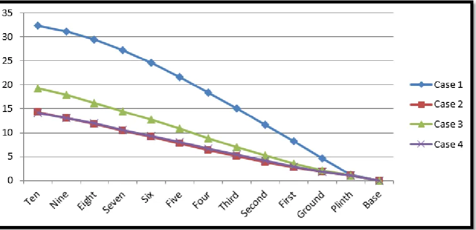
1. Storey Drift:
Fig. 6: Storey Drift
2. Storey Displacement (in mm):
25 | P a g e
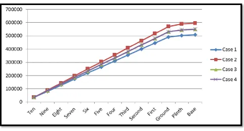
3. Storey Shear (in kN):
Fig. 8: Storey Shear (in kN)
4. Storey Overturning Moment (in kNm):
26 | P a g e V. SUMMARY & CONCLUSIONS:
It is clear to all that the seismic hazard has to be carefully evaluated before the construction of important and high-rise structures. Based on the above analytical study carried out on 4 models, it is evident that buildings with shear walls behave more effectively than conventional frames when subjected to seismic loads. The following deductions are made from the obtained results:
The frame with Shear Walls clearly provides
more safety to the designers and although it proves to be a little costly, they are extremely effective in terms of structural stability.
Due to the falling of the zone, the earthquake hazard will also increase. In such cases, use of shear walls become mandatory for achieving safety in design.
In all the systems, the Storey Drift is within the permissible limits as per IS:1893 (Part 1). However CASE 4, closely followed by CASE 2, showed better results when compared to other models. This lead us to believe that when Shear Walls are placed at the center of the geometry in the form of a box or at the corners, the structures behave in a more stable manner. This practice of providing Box-type Shear Walls is becoming more popular now-a-days as high rise structures generally have a lift system and these box-type shear walls serve the dual purpose of Shear walls and also as a vertical duct or passage for the movement of the lifts.
The Storey Displacement also follows a similar pattern as storey drifts. Best results are obtained for CASE 4, followed closely by CASE 2, proving again that the optimum position of shear walls is either at the center of the building or at the corners.
The main difference in the behaviors of CASE 4
and CASE 2 can be noted when comparing Storey Shear. CASE 2 displayed very higher values of storey shear as compared to the other models. Here again CASE 4 proved to be the best.
Overturning Moments are minimum in
conventional buildings. However the lower performance of CASE 1 in terms of Storey Drifts, Storey Displacements and Lateral Loadings make it unfit for use in higher seismically active zones.
To further increase the effectiveness of the structure, earthquake resisting techniques such as Seismic Dampers & Base Isolation can be used. It is hence safe to conclude that among all other
possibilities, CASE 4 (Building with Box-type Shear Wall at the center of the geometry) is the ideal framing technique for high rise buildings.
REFERENCES:
1. Anshumn. S, Dipendu Bhunia, Bhavin Rmjiyani
(2011), “Solution of shear wall location in Multi-storey building.” International Journal of Civil Engineering Vol. 9, No.2, Pages 493-506.
2. M. Asharaf, Z. A. Siddiqi, M. A. Javed,
“Configuration of Multi-storey building subjected to lateral forces”. Asian Journal of Civil Engineering (Building & Housing), Vol. 9, No. 5, Pages 525-537. 3. H.S. Kim, D.-G. Lee “Analysis of shear wall with openings using super elements” Engineering Structures 25 (2003), Pages 981–991
4. M. Shariq, H. Abbas, H. Irtaza, M. Qamaruddin
“Influence of openings on seismic performance of masonry building walls” Building and Environment 43 (2008) Pages 1232–1240
5. Sid Ahmed Meftah, Abdelouahed Tounsi, Adda
Bedia El Abbas “A simplified approach for seismic calculation of a tall building braced by shear walls and thin-walled open section structures” Engineering Structures 29 (2007), Pages 2576–2585
6. Quanfeng Wang, Lingyun Wang, Qiangsheng Liu
“Effect of shear wall height on earthquake response” Engineering Structures 23 (2001), Pages 376–384
7. P.A. Hidalgo, R.M. Jordan, M.P. Martinez “An
analytical model to predict the inelastic seismic
behavior of Shear-wall, reinforced concrete
structures” Engineering Structures 24 (2002), Pages 85–98
8. Duggal S. K.(2010), “ Earthquake Resistant Design Structues”. Oxfored University press YMCA library building, Jai Singh road, New Delhi.
9. IITK-BMTPC : Earthquake Tips.
10. Bureau of India Standard, IS-1893, Part 1 (2002), “Criteria for earthquake resistant design of structures.” Part 1
11. Bureau of Indian Standard, IS-456(2000), “Plain and
![Fig. 4: Case [4]](https://thumb-us.123doks.com/thumbv2/123dok_us/8726750.1745409/3.595.311.541.76.288/fig-case.webp)