Power Flow Control By using D-FACTS Concept Through DPFC
Nagaraju Gairaboina
1, Shankar Nunavath
21M. Tech (PE), Department of EEE, Sujala bharathi Engineering College1 2
Professor (HOD), Department of EEE, Sujala Bharathi Engineering College 2
I.INTRODUCTION:
THE GROWING demand and the aging of networks make it desirable to control the power flow in power-transmission systems fast and reliably. The flexible ac-power-transmission
system (FACTS) that is defined by IEEE as ―a powerelectronicbased system and other static equipment that provide control of one or more ac-transmission system parameters to enhance controllability and increase power transfer capability‖ , and can be utilized for power-flow
control. Currently, the unified power-flow controller (UPFC)is the most powerful FACTS device, which can simultaneously control all the parameters of the system: the line impedance, the transmission angle, and bus voltage. The UPFC is the combination of a static synchronous compensator (STATCOM) and a static synchronous series compensator (SSSC), which are coupled via a common dclink, to allow bidirectional flow of active power between the series output terminals of the SSSC and the shunt output terminals of the STATCOM]. The converter in series with the
line provides the main function of the UPFC by injecting a four-quadrant voltage with controllable magnitude and phase. The injected voltage essentially acts as a synchronous ac voltage source, which is used to vary the transmission angle and line impedance, there by independently controlling the active and reactive power flow through the line. The series voltage results in active and reactive power injection or absorption between the series converter and the transmission line. This reactive power is generated internally by the series converter (see e.g., SSSC ), and the active power is supplied by the shunt converter that is back-to-back connected. The shunt converter controls the voltage of the capacitor by absorbing or generating active power from the bus; therefore, it acts as a synchronous source in parallel with the system. Similar to the STATCOM, the shunt converter can also provide reactive compensation for the bus. The components of the UPFC handle the voltages and currents with high rating; therefore, the total cost of the system is high. Due to the common dc-link interconnection, a influence the whole system. To achieve the required reliability for power systems, bypass circuits and redundant backups (backup transformer,
etc.) are needed, which on other hand, increase the cost. Accordingly, the UPFC has not been commercially used, even though; it has the most advanced control capabilities.
Abstract:
In this paper we presents a new component within the flexible ac-transmission system (FACTS) family, called distributed flow controller (DPFC). The DPFC is derived from the unified power-flow controller (UPFC). The DPFC can be considered as a UPFC with an eliminated common dc link. The active power exchange between the shunt and series converters, which is through the common dc link in the UPFC, isnow through the transmission lines at the third-harmonic frequency. The DPFC employs the distributed FACTS (DFACTS)concept, which is to use multiple small-size single-phase converters instead of the one large-size three-phase series converter in the UPFC. The large number of series converters provides redundancy, thereby increasing the system reliability. As the D-FACTS converters are single-phase and floating with respect to the ground, there is no high-voltage isolation required between the phases. Accordingly, the cost of the DPFC system is lower than the UPFC. The DPFC has the same control capability’s the UPFC, which comprises the adjustment of the line impedance, the transmission angle, and the bus voltage. The principle and analysis of the DPFC are presented in this paper and the corresponding experimental results are also shown.Fig.1.Flowchart from UPFC to DPFC
This paper introduces a new concept, called distributed power-flow controller (DPFC) that is derived from the UPFC.
The same as the UPFC, the DPFC is able to control all system parameters. The DPFC eliminates the common dc link between the shunt and series converters. The active power
exchange between the shunt and the series converter is through the transmission line at the third-harmonic frequency. The series converter of the DPFC employs the distributed FACTS (D-FACTS) concept.
Comparing with the UPFC, the DPFC have two major advantages: 1) low cost because of the low-voltage isolation and the Low component rating of the series converter and 2)
high reliability because of the redundancy of the series converters. This paper begins with presenting the principle of the DPFC, followed by its steady-state analysis.
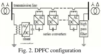
Fig. 2. DPFC configuration
After a short introduction of the DPFC control, the paper ends with the experimental results of the DPFC.
I.DPFC PRINCIPLE
Two approaches are applied to the UPFC to increase the reliability and to reduce the cost; they are as follows. First, eliminating the common dc link of the UPFC and second
Distributing the series converter. By combining these two approaches, the new FACTS device—DPFC is achieved. The DPFC consists of one shunt and several series-connected converters. The shunt converter is similar as a STATCOM,
While the series converter employs the D-FACTS concept, which is to use multiple single-phase converters instead of one
large rated converter. Each converter within the DPFC is independent and has its own dc capacitor to provide the required dc voltage. The configuration of the DPFC is shown
in Fig. 2. As shown, besides the key components, namely the shunt and series converters, the DPFC also requires a high pass
filter that is shunt connected on the other side of the transmission line, and two Y–Δ transformers at each side of the line. The reason for these extra components will be
explained later. The unique control capability of the UPFC is given by the back-to-back connection between the shunt and series converters, which allows the active power to exchange freely. To ensure that the DPFC have the same control capability as the UPFC, a method that allows the exchange of
active power between converters with eliminated dc link is the prerequisite.
A. Eliminate DC Link
Within the DPFC, there is a common connection between the ac terminals of the shunt and the series converters, which
components. According to the Fourier analysis, a no sinusoidal voltage and current can be expressed by the sum of sinusoidal functions in different frequencies with different amplitudes. The active power resulting from this non
Sinusoidal voltage and current is defined as the mean value of the product of voltage and current. Since the integrals of all the cross product of terms with different frequencies are zero, the active power can be expressed by
P= iIicosφi ( 1) where Vi and Ii are the voltage and current at the ith harmonic frequency, respectively, and φi is the corresponding angle
between the voltage and current. Equation (1) describes that the active power at different frequencies is isolated from each other and the voltage or current in one frequency has no
influence on the active power at other frequencies. The independency of the active power at different frequencies gives the possibility that a converter without power source can generate active power at one frequency and absorb this power from other frequencies. By applying this method to the DPFCThe shunt converter can absorb active power from the grid at the fundamental frequency and inject the current back into the
grid at a harmonic frequency. This harmonic current will flow through the transmission line. According to the amount of required active power at the fundamental frequency, the
DPFC series converters generate a voltage at the harmonic frequency, thereby absorbing the active power from harmonic components. Assuming a lossless converter, the active power generated at fundamental frequency is equal to the power absorbed from the harmonic frequency. The high-pass filter within the DPFC blocks the fundament frequency components and allows the harmonic components to pass, thereby providing a return path for the harmonic components. The shunt and series converters, the high-pass filter, and the ground form the closed loop for the harmonic current. Due to the unique characters of third-harmonic frequency components, the third harmonic is selected to exchange the active power in the DPFC. In a three-phase
system, the third harmonic in each phase is identical, which is referred to as ―sequence.‖ The zero-sequence harmonic
can be naturally blocked by Y–Δ transformers, which are widely used in power system to change voltage level. Therefore, there is no extra filter required to prevent the harmonic leakage to the rest of the network. In addition, by using the third harmonic, the costly high-pass filter can be replaced by a cable that is connected between the neutral point of the Y–Δ transformer on the right side and the ground.
Because the Δ winding appears open circuit to the third harmonic current, all harmonic current will flow through the Y-winding and concentrate to the grounding cable. Therefore,
the large-size high-pass filter is eliminated.
Another advantage of using third harmonic to exchange active power is that the way of grounding of Y– Transformers can be used to route the harmonic current in a meshed network. If the branch requires the harmonic current to flow through, the neutral point of the Y–Δ transformer at the other side in that branch will be grounded and vice versa. Theoretically, the third-, sixth-, and ninth-harmonic frequencies are all zero-sequence, and all can be used to exchange active power in the DPFC. As it is well known, the capacity of a transmission line to deliver power depends on its impedance. Since the transmission-line impedance is inductive and proportional to the frequency, high-transmission frequencies will cause high impedance. Consequently, the Zero-sequence harmonic with the lowest frequency—third harmonic is selected.
B.Distributed Series Converter
The D-FACTS is a solution for the series-connected FACTS, which can dramatically reduce the total cost and increase the reliability of the series FACTS device. The idea of the D-FACTS is to use a large number of controllers with low rating instead of one large rated controller. The small controller is a single-phase converter attached to transmission
lines by a single-turn transformer. The converters are hanging on the line so that no costly high-voltage isolation is required.
The single-turn transformer uses the transmission line as the secondary winding, inserting controllable impedance into the
The structure of the D-FACTS results in low cost and high reliability. As D-FACTS units are single-phase devices floating on lines, high-voltage isolations between phases are avoided. The unit can easily be applied at any transmission voltage level, because it does not require supporting phase ground isolation. The power and voltage rating of each unit is relatively small. Further, the units are clamped on transmission lines, and therefore, no land is required. The redundancy of the D-FACTS provides an uninterrupted operation during a single module failure, thereby giving a
much higher reliability than other FACTS devices.
B.DPFC Advantages
The DPFC can be considered as a UPFC that employs the DFACTS concept and the concept of exchanging power through harmonic. Therefore, the DPFC inherits all the
advantages of the UPFC and the D-FACTS, which are as follows.
1) High control capability. The DPFC can simultaneously control all the parameters of the power system: the line impedance, the transmission angle, and the bus voltage. The elimination of the common dc link enables separated installation of the DPFC converters. The shunt and series converters can be placed at the most effectively location. Due to the high control capability, the DPFC can also be used to improve the power quality and system stability, such as low frequency power oscillation damping , voltage sag restoration, or balancing asymmetry.
2) High reliability. The redundancy of the series converter gives an improved reliability. In addition, the shunt and series converters are independent, and the failure at one place
will not influence the other converters. When a failure occurs in the series converter, the converter will be short-circuited by bypass protection, thereby having little influence to the
network. In the case of the shunt converter failure, the shunt converter will trip and the series converter will stop providing
active compensation and will act as the D-FACTS controller.
One is to increase the turn ratio of the single-phase transformer of the series converter to reduce the magnitude of the current that flows into the converter. The other way is to use the dc capacitor with a larger capacitance.
Fig.4 Block diagram of shunt converter control
3) Low cost. There is no phase-to-phase voltage isolation required by the series converter. Also, the power rating of each converter is small and can be easily produced in series production lines. However, as the DPFC injects extra current at the third harmonic frequency into the transmission line, additional losses in the transmission line and transformer should be aware of.
I.DPFC CONTROL
To control the multiple converters, DPFC consists of three types of controllers; they are central controller, shunt control, and series control. The shunt and series control are local
controllers and are responsible for maintaining their own converters’ parameters. The central control takes account of the DPFC functions at
the power-system level. The function of each controller is listed next.
A. Central Control
The central control generates the reference signals for both the shunt and series converters of the DPFC. It is focused on the DPFC tasks at the power-system level, such as power flow
control, low-frequency power oscillation damping, and balancing of asymmetrical components. According to the system requirement, the central control gives corresponding voltage-reference signals for the series converters and reactive current signal for the shunt converter. All the reference signals
generated by the central control are at the fundamental frequency.
C.Series Control
Each series converter has its own series control. The controller is used to maintain the capacitor dc voltage of its own converter by using the third-harmonic frequency components and to generate series voltage at the fundamental frequency that is prescribed by the central control. The third-harmonic frequency control is the major control
loop with the DPFC series converter control. The principle of the vector control is used here for the dc-voltage control. The third-harmonic current through the line is selected as the
component. There are two possible ways to reduce this ripple.
B.Shunt Control
The block diagram of the shunt converter control is shown
The objective of the shunt control is to inject a constant third harmonic current into the line to provide active power for the series converters. The third-harmonic current is locked with the bus voltage at the fundamental frequency. A PLL is used to capture the bus-voltage frequency, and the output phase signal of the PLL is multiplied by three to create a virtual rotation reference frame for the third-harmonic component. The shunt converter’s fundamental frequency control aims to inject a controllable reactive current to grid and to keep the capacitor dc voltage at a constant level. The control for the fundamental frequency components consists of two cascaded controllers. The current control is the inner control loop, which is to modulate the shunt current at the fundamental frequency.
Fig,5 .Experimental set up
The q-component of the reference signal of the shunt converter is obtained from the central controller, and dcomponent is generated by the dc control.
IV.RESULTS
An experimental setup has been built to verify the principle and control of the DPFC. One shunt converter and six single phase series converters are built and tested in a scaled
network. Two isolated buses with phase difference are connected by the line. Within the experimental setup, the shunt converter is a single-phase inverter that is connected between the neutral point of the Y–Δ transformer and the ground. The inverter is powered by a constant dc-voltage source. The specifications of the DPFC experimental setup are listed in the Appendix (see Table I). Within the setup, multiple series converters are controlled by a central controller. The central controller gives the reference voltage signals for all series converters. The voltages and currents within the setup are measured by an oscilloscope and processed in computer by using the MATLAB.
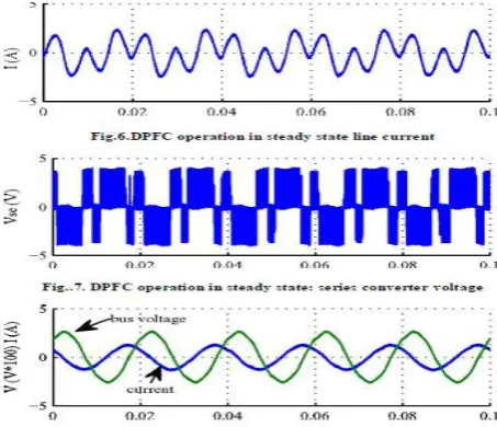
To verify the DPFC principle, two situations are demonstrated: the DPFC behavior in steady state and the step response. In steady state, the series converter is controlled to insert a voltage vector with both d- and q -component, which is Vse,d,ref = 0.3 V and Vse,q,ref = −0.1 V. Figs. 6–8 show one operation point of the DPFC setup. For clarity, only the waveforms in one phase are shown. The voltage injected by
waveform represents the dc- capacitor voltage, which is well maintained by the third harmonic component in steady state. As shown, the dc voltage has a small oscillation; however, it does not influence the DPFC control.
Fig.8. DPFC operation in steady state: bus voltage and current at the Δsideof the transformer
Fig. 8 demonstrates the third-harmonic filtering by the Y–Δ transformers. There is no third-harmonic current or voltage leaking to the Δ side of the transformer.
V. CONCLUSION
This paper has presented a new concept called DPFC. The DPFC emerges from the UPFC and inherits the control capability of the UPFC, which is the simultaneous adjustment
of the line impedance, the transmission angle, and the bus voltage magnitude. The common dc link between the shunt and series converters, which is used for exchanging active
power in the UPFC, is eliminated. This power is now transmitted through the transmission line at the third-harmonic frequency. The series converter of the DPFC employs the DFACTS
concept, which uses multiple small single phase converters instead of one large-size converter. The reliability of the DPFC is greatly increased because of the redundancy of the series converters. The total cost of the DPFC is also much lower than the UPFC, because no high-voltage isolation is required at the series-converter part and the rating of the
REFERENCES
[1]. Y.-H. Song and A. Johns, Flexible ac Transmission Systems (FACTS) (IEE Power and Energy Series), vol.
30. London, U.K.:Institution of Electrical Engineers, 1999.
[2]. N. G. Hingorani and L. Gyugyi, Understanding FACTS : Concepts andTechnology of Flexible AC
Transmission Systems. NewYork: IEEE Press, 2000.
[3]. L.Gyugyi, C.D. Schauder, S. L.Williams, T. R. Rietman,D. R.Torgerson,andA. Edris, ―The unified
powerflowcontroller:Anewapproach to power transmission control,‖ IEEETrans. Power Del., vol. 10, no.
2, pp. 1085–1097, Apr. 1995.
[4]. A.-A. Edris, ―Proposed terms and definitions for flexible ac transmission System (facts),‖ IEEE Trans. Power Del., vol. 12, no. 4, pp. 1848–1853, Oct. 1997.
[5]. K. K. Sen, ―Sssc-static synchronous series compensator: Theory, modeling, and application,‖ IEEE Trans.
Power Del., vol. 13, no. 1,pp. 241–246, Jan. 1998.