41
Numerical Methods in Civil Engineering
Application of the multi-laminate sub-loading surface model in the
simulation of a pipe-jacking operation
S.A. Ghoreishian Amiri *
ARTICLE INFO Article history: Received: March 2014. Revised: August 2014. Accepted: November 2014.
Keywords:
multi-laminate framework, sub-loading surface model, pipe-jacking
Abstract:
In this paper a constitutive model formulated in the framework of multi-laminate models is applied to analyze pipe-jacking processes. The multi-laminate -based models consider various integration planes to formulate the stress-strain relationship. This basic feature of the framework has the advantage that yield criteria, flow and hardening rules are formulated on planes rather than in three-dimensional stress space. In the proposed model, constitutive equations of the integration planes are derived based on the sub-loading surface plasticity framework. It is demonstrated that the development of large deformation and cracks formation which are the main difficulties in the simulation of pipe-jacking processes can be captured with this model. The ability of the model in the handling of these difficulties is verified with the simulation a laboratory pipe-jacking test. The simulation results show reasonable agreement with the test data.
.
1. Introduction
Rapid growth in urban development shows the importance of using underground space to upgrade and expand the existing infrastructure in order to satisfy the updating demands. Tunneling provides the necessary infrastructures and accommodation for future needs on one hand and minimizes surface impacts on the other. Tunnels are essentially important in accommodating transportation systems, communication, and utility networks such as water supply and sewage disposal pipelines.
Trenchless technologies such as pipe-jacking operation have been widely used for the installation of new pipelines and the replacement of existing sub-standard or undersized pipelines. Pipe-jacking is a system of directly installing pipes behind a shield machine by hydraulic jacking from a derived shaft such that the pipes form a continuous string in the ground [9]. It has several benefits such as avoidance of open excavation and reduction of damage to adjacent infrastructures.
Prediction of soil deformation and required jacking force are some of the important features for designing pipe-jacking projects. Appropriate prediction of the required jacking force is structurally important to complete the drive
*Corresponding author: Civil Engineering Department of University of Qom, Qom, Iran.Email:[email protected]
without damage to pipes and joints from excessive stress concentration.
Moreover, because of possible damage to adjacent services and structures those are induced by absolute or differential movements, appropriate approximation of ground deformation during the process is very important.
Recently, the prediction of ground deformation and required jacking force during micro tunneling operations have been carried out by efficient numerical analysis based on the finite element method [1,2,12,15,21,23]. Because of complicated intrinsic of three-dimensional analysis and Due to cost effectiveness, in many cases, researchers [15,20] adapted a two-dimensional plane strain or axi-symmetrical approach of the tunnel transverse or longitudinal section. However, field results and theoretical analyses show that the general stress and displacement patterns around the tunnel or pipelines are three-dimensional and different from the plane strain transverse section [10,11].
In addition to the requirement of three-dimensional modeling, ill conditioning of stiffness matrix due to large deformations and formation of tension cracks in the soil surface are the other difficulties in the simulation of a pipe-jacking operation. Therefore, the standard form of the updated Lagrangian finite element formulation must be enhanced with common methods such as non-local models
Numerical Methods in Civil Engineering, Vol. 1, No.2,December.2014
[13,14], enhanced finite element models [3,13] and mesh adaptivity techniques [26].
In this paper a pragmatic concept is presented based on the intrinsic feature of the multi-laminate -based models. The proposed framework is capable of considering large deformations and formation of tension cracks only with some physical and very simple assumptions. The efficiency of the proposed method is verified by comparing with a pipe splitting operation test which was carried out in the University of Birmingham, UK [19].
Note that, throughout this paper the stress and strain are taken positive for compression, and the stress for soils is taken as effective stress.
2. Multi-Laminate Framework
Geomaterials consisting of grains in contact and surrounding voids are particulate media that are mostly considered continuum for ease. The accurate behavior of such particulate materials should be investigated through micro-mechanics. To investigate the micro-mechanical behavior of geomaterials, certainly, the spatial distribution of contact points and orientation of grains must be identified. This type of analysis is very complicated to be applied in the level of engineering problems. In engineering point of view, the main goal is to formulate the macro-behavior of granular materials in terms of micro-quantities. In this matter, the multi-laminate could be very efficient. The framework is like a bridge between micro and macro scale upon the satisfaction of minimum potential energy level during any applied stress/strain increments. The concept of multi-laminate models is based on a certain number of sampling (integration or contact) planes which constitute the elastic-plastic behavior of the soil. Then, the overall behavior of the soil can be modeled as the summation of the behavior of these planes.
In the micro-mechanical point of view, the applied load on a soil medium is tolerated by the forces developing at the contacts between the soil particles. It makes the major contribution to the overall strain and this contribution is accounted for in the multi-laminate model. Since, the individual grains are not modeled in a discrete way, the interactions between grains are considered in an average form on the contact planes. Therefore, in the multi-laminate framework each point in the soil body is disintegrated by some contact planes (fig. 1). In an ideal case, the integration is considered as the summation of the individual micro effects corresponding to infinite number of micro contact planes. But employing infinite number of planes is not possible, so finite numbers of planes are employed for calculating required integrals with numerical methods. Numerical integration rules govern the number, direction and orientation of the contact planes. The choice of 13 planes for the solution of any three dimensional problem is a fair number [16].
It is worth noting, usually the same mathematical relations hold for all planes. However, this assumption is not strictly required. Moreover, inherent anisotropy may be easily introduced in multi-laminate based models by varying parameters over the planes prior to loading [21,25].
Fig.1: Contact planes in a point inside soil body (from Schuller and Schweiger 2002)
Depending on the stress path applied to the soil mass, certain contact planes will be activated while the other planes remain inactive. Therefore, induced anisotropy depending on the stress path is automatically accounted for. Moreover, rotations of principal stress axes which generally take place in boundary value problems can be simulated without any additional hypothesis. The capabilities of the multi-laminate framework to respond to stress path in which the principal stress axes rotate were demonstrated by Schweiger and Schuller (2000).
When implementing a multi-laminate model into a finite element code, the contact planes are located at each integration point of the finite element mesh. The constitutive relations for describing material behaviour are formulated on the planes in local coordinate system. Therefore, the stress state
σ at an integration point istransformed into normal and shear stresses
n,
on each plane utilizing a transformation matrix
T :n
T σ(1)
By applying a constitutive model, compliance matrix ep
i
C for each of the individual planes could be calculated. Since the constitutive equations are defined on the level of the contact planes and formulated in terms of normal and shear stresses, relatively simple mathematical expression can be used even to describe complex material behavior. The global compliance matrix
Cep is obtained by numerical integration of the compliance matrix calculated for the individual planes and using the transformation matrix
T :13
1
8
ep ep T
i i i
w
C
T C T (2)where
w
i are weight factors which are chosen according to numerical integration rules.43
3. Constitutive Formulation
Sub-loading surface plasticity framework is employed to derive the constitutive equations in the contact planes. Implementation of sub-loading surface model in the multi-laminate framework is reviewed in detail by Sadrnejad and Ghoreishian (2010). Therefore, only a brief introduction to the constitutive equations is presented here.
There are two basic surfaces in the sub-loading surface model to describe the material behavior: the normal yield surface and the sub-loading surface. The normal yield surface is the renamed form of the conventional yield surface while its interior is not regarded as a purely elastic domain. In other word, in the sub-loading surface model there is no purely elastic deformation in the loading process. The sub-loading surface is introduced as a surface which always passes through the current stress point while keeping a similar shape to the normal yield surface with respect to the origin of stress space, i.e. σ0. The sub-loading surface is always within or on the normal yield surface. The following geometrical properties are the results of these assumptions:
a. Each line connecting an arbitrary point on or within the sub-loading surface and its conjugate point on or within the normal yield surface joins at the similarity center which is the origin of the stress space in the present case.
b. Each ratio of the length of an arbitrary line connecting two points on or inside the sub-loading surface to the length of another line which connects their conjugate points on or inside the normal yield surface is identical. This ratio is called similarity ratio, and it is equal with the ratio of the sizes of these surfaces.
The similarity ratio of the sub-loading surface to the normal yield surface is also called normal yield ratio, R. If
0
R , size of the sub-loading surface will be equal to zero, if 0 R 1, the sub-loading surface will exist inside the normal yield surface and if R1, it will lie on the normal yield surface.
Since there is no purely elastic domain inside the yield surface, the sub-loading surface constitutive equations fulfill the smoothness condition. So it can predict a smooth elastic-plastic transition [6].
The strain rate of each plane, ε, is decomposed into the
elastic strain rate, εe, and plastic strain rate, εp:
e p
i i
i
ε ε ε (3)
The elastic strain rate is given by:
1/ 3 0 ;
0 1/
e
e e
e
n n
G K
C C (4)
where, K and G are the bulk and shear modulus, respectively. The elastic shear modulus Gis given by:
3 (1 2 )
2(1 )
K
G
(5)
where,
is the Poisson ratio.The normal yield surface is described by the following function:
0
( y) exp( H )
f F
σ (6)
where F0 is the initial value for F , and are the slopes of the normal consolidation and the swelling curves in lnvlnp space, respectively (
v
is the specific volume and ptr( ) / 3σ is pressure), scalar H is the isotropichardening/softening variable and σy is the stress state point on the normal yield surface.
The sub-loading surface is given by the following function:
2
( ) ( )
3
n
n
f R F H
m
σ (7)
where, m is a material parameter describing the stress ratio on the critical state line. The normal yield and sub-loading surfaces are illustrated in figure 2.
Fig.2: Normal yield and sub-loading surfaces in contact planes
The evolution rule for isotropic hardening/softening behavior is defined as:
p n
H
(8)Equation (8) indicates that, when soil sample compacts, the size of normal yield surface will increase and the hardening behavior is captured by the model. On the other hand, if soil sample expands, the size of normal yield surface will decrease and the softening process is captured without any additional hypothesis.
Numerical Methods in Civil Engineering, Vol. 1, No.2,December.2014
By assuming associated flow rule, the plastic strain rate is calculated as:
1
;
p
p p T
p p
n
n
M
C
C
N N
(9)where, vector N is the normalized outward normal of the sub-loading surface at the current stress state:
( ) ( )
f f
σ σ
N
σ σ (10)
and Mp is calculated as follow:
( ) ( )
p F U T
M h
F R
N σ
(11)where, h is the component of N in the direction of n, and U is defined as:
ln
U u R (12)
where,
u
is a material parameter.Loading criterion in sub-loading surface models is given as [6]:
1
1
0 0
0 0
T p
T p
e
e
N ε ε
N ε ε
C
C
(13)
It is worth noting, since the stress state always lies on the sub-loading surface (which just plays the role of loading surface), equation (13) is the only judgment required in the loading criterion of the constitutive equation in each plane.
Mechanism of dilation behavior in this model is controlled with the critical state line. The critical state line connects the peak points of sub-loading surface and normal yield surface. The normal vector at the peak point of the sub-loading surface does not have any component in the volumetric strain direction. The volumetric component of the normal vector on the sub-loading surface at the left-hand side of the peak point is negative and it is positive at the write-hand side of this point (Fig. 3).
Hashiguchi and his coworkers[7] demonstrated that, a rough numerical calculation with large load steps is allowed in the sub-loading surface constitutive equations, because the stress state will be automatically drawn back to the normal yield surface even if it goes out of the normal yield surface.
Fig.3: Sub-loading and normal surfaces and their peak points for dilation control
4. Application to Numerical Simulation of a Pipe-Jacking Operation
In a pipe-jacking project, large amount of soils should be displaced and compacted during the operation. In an elastoplastic analysis, if large deformations occur, the stress state will lie on the perfect-plastic line and consequently the stiffness matrix will fall into the ill condition. By using the multi-laminate framework, only the stress state of some specific planes which are in the direction of large deformation will lie on the perfect-plastic line and the other planes will behave normally. When the stress state of a contact plane approaches to the perfect-plastic line, evolution of stiffness matrix on this plane will be infinitesimal. Therefore, the stiffness matrix of the plane could be frozen before falling into the ill condition. In other words, when an integration point encounters large strains in specific directions, stiffness of the integration point in these directions will be frozen just before it is lying on the perfect-plastic line. However, stiffness of the point in other directions (other contact planes) will be calculated normally.
Moreover, during a pipe-jacking operation, because of the swelling of the soil, some tension cracks may be generated within the soil body. An appropriate numerical method should be able to consider the effects of the cracks on the soil behaviour. If a crack forms in a specific direction, stiffness of the soil could be negligible in this direction. By using the multi-laminate framework, generation of tension cracks in the soil body will be captured by the generation of negative normal stress on the contact planes which are lying on the direction of the cracks. Therefore, effects of crack generation could be considered in the model by neglecting the stiffness of these planes. Consequently, soil could move freely along the crack direction.
The proposed method is employed for numerical analysis of a pipe splitting operation test which was performed in the University of Birmingham, UK [19]. The test was carried out in a tank with 3.0 m length, 2.3 m width and 2.0 m height. The existing pipe (which should be replaced) was a ductile iron pipe with the outside diameter
45
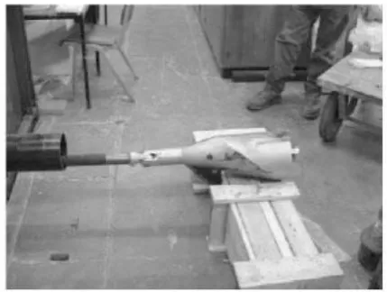
of 175 mm. The cover depth of the pipe was 900 mm andthe soil was typologically concreting sand. The pipe splitting device was a conic shaped Clampburster with the maximum outside diameter of 220 mm (Fig. 4).
Fig.4: Clampburster pipe splitting device (from Rogers et al. 2002)
Figure 5 shows the finite element mesh of the soil body containing 96 elements and 656 nodes. Hexahedral elements with second order polynomial shape functions are used for discretization of the physical domain. The orthogonal displacements of the laterals and bottom boundaries of the media are constrained.
Fig.5: Finite element mesh of the model
For simulating the replacement process, geometry of Clampburster device are applied to the soil nodes around the existing pipe. Since Clampburster device do not contact with the soil body (because of the existing pipe line), no longitidunal movement is considered for the soil nodes. So, pipe replacement is simulated with radial displacement of the soil nodes around the old pipe.
For calibrating the model parameters, experimental results of a node at 100 mm above the pipe centerline in the first measurement section (0.75 m from the beginning) is selected as the base point (Fig. 6).
Fig.6: Calibration results for a node above the pipe centerline with 100 mm distance
So, the model parameters used in the simulation are listed as bellow:
0
0.5, 0.0006, 0.25 0.06
75, 4000
m
u F kPa
Figure 7 shows the comparison of experimental data and numerical results for two other nodes. These two nodes are located at a distance of 100 mm below and on the left of the pipe centreline.
Fig.7: Comparison results for two nodes below and larboard the pipe centreline with 100 mm distance
Figure 8 shows the soil deformation at the entrance section of the tank after 30 cm advancement of the machine. Swelling of the soil surface is shown in Figure 9. Maximum value of swelling took place above the pipe centreline.
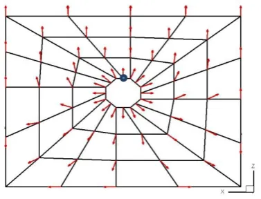
Direction of nodal displacements for the entrance section is shown in Figure 10. As it is shown in the figure, the nodes near the pipe line have displaced in the radial direction. However, because of the high stiffness of the walls, farther nodes have rotated to the softer sections.
Numerical Methods in Civil Engineering, Vol. 1, No.2,December.2014
Fig.8: Deformed shape of the soil body at the entrance section
Fig.9: Deformation of the soil surface at the entrance section
Fig.10: Direction of nodal displacement at the entrance section
Figure 11 shows the soil behavior for a node located around the pipe line (the node is highlighted in fig. 10). As shown in the figure, deviatoric and volumetric strains of the node are about 100% and 10%, respectively. It shows the efficiency of the multi-laminate model for simulating large deformations.
Fig.11: Soil behaviour curves: a) deviatoric stress-deviatoric strain; b) volumetric strain- deviatoric strain
The required jacking force during the operation of 30 cm of pipe line is shown in figure 12. As shown in the figure, in the early stages of the operation, diameter of the conic tip of Clampburster device is smaller than the initial diameter of the pit and therefore, machine advancement does not encounter any resistance offered by the soil.
Fig.12: Required jacking force during the operation
Figure 13 shows the zone of cracks generation. In this zone, normal stress of some contact planes became negative. Direction of cracks could be captured with the direction of the contact planes. It is worth noting the unsymmetrical shape of crack zone is because of the unsymmetrical mesh generation.
Fig.13: Zone of crack generation
(m)
47
5. Conclusion
An application of a multi-laminate model to numerical simulation of pipe-jacking process is presented. The concept of this model is based on a certain number of sampling planes which constitute the elastic-plastic behavior of the soil. The soil behavior presents as the summation of behavior on the sampling planes. These features lead the model to overcome the numerical difficulties such as large deformations and cracks formation which are commonly occurs in the simulation of pipe-jacking process.
The validity of the proposed method has been investigated with the laboratory testing data of pipe splitting operations carried out in the University of Birmingham, UK.
References:
[1] Abufarsakh, M., Voyiadjis, G., “Computational model for the simulation of the shield tunneling process in cohesive soils”, Int. J. Numer. Anal. Meth. Geomech., vol. 23, 1999, p. 23-44.
[2] Barala, M., Camusso, M., Aiassa, S., “Analysis of jacking forces during micro-tunneling in limestone”, Tun. Undgr. Spc. Tech., vol. 21, 2006, p. 668-683.
[3] Belytschko, T., Fish, J., Englemann, B. E., “A finite element with embedded localization zones”, Com. Meth. Appl. Mech. Eng., vol. 70, 1988, p. 59-80.
[4] De Borst, R., “Simulation of strain localization: a re-appraisal of the Cosserat continuum”, Eng. Comp., vol. 8, 1991, p. 317–32.
[5] Brinkgreve, R., Vermeer, P., “A new approach to softening plasticity”, In Pande & Pietruszczak (Ed.), Proc. 5th Int. Symp. Numerical Models in Geomechanics - NUMOG V, 1995, Davos, p. 193-202.
[6] Hashiguchi, K., “Fundamentals in constitutive equation: continuity and smoothness conditions and loading criterion”, Soils Found., vol. 40 no. 3, 2000, p.155- 161.
[7] Hashiguchi, K., Saitoh, K., Okayasu, T., Tsutsumi, S., “Evaluation of typical conventional and unconventional plasticity models for prediction of softening behaviour of soils”, Geotechnique, vol. 52 no. 8, 2002, p. 561–578.
[8] Hicks, M., “An adaptive mesh study of localisation in a saturated soil”, In Yuan (Ed.), Proc. 9th Int. Conf. Computer Methods and Advances in Geomechanics, 1997 , Wuhan, p. 1853–1858.
[9] ISTT, Trenchless Tecchnology Guidelines, 1998.
[10] Lee, K. M., Rowe, R. K., “Finite element modeling of the three-dimensional ground deformation due to tunneling in soft cohesive soils: part I – method of analysis”, Comput. Geotech., vol. 10, 1990a, p. 87- 109.
[11] Lee, K. M., Rowe, R. K., “Finite element modeling of the three-dimensional ground deformation due to tunneling in soft cohesive soils: part II – results”, Comput. Geotech., vol. 10, 1990b, p. 111-138.
[12] Lee, K. M., Rowe, R. K., Lo, K. Y., “Subsidence owing to tunneling. I. estimating the gap parameter”, Can. Geotech. J.,vol. 29, 1992, p. 929- 940.
[13] Leroy, Y., Ortiz, M., “Finite element analysis of strain localization in frictional materials”, Int. J. Num. Analyt. Meth. Geomech., vol. 13, 1989, p. 53–74.
[14] Marcher, T., Vermeer, P., “Macromodelling of softening in non-cohesive soils”, Proc. Int. Symp. Continuous and Discontinuous Modelling of Cohesive Frictional Materials - CDM 2000: Springer, 2000, p. 89-108.
[15] Ng, M. C., Lo, K. Y., Rowe, R. K. (1986). Analysis of field performance – the Thunder Bay Tunnel. Can. Geotech. J., 23, 30-50.
[16] Pande, G., Sharma, K., “Multi-laminate of clays- a numerical evaluation of the influence rotation of principal stress axis”, Int. J. Numer. Anal. Methods Geomech., vol. 7, 1983, p. 397- 418.
[17] Rogers, C. D., “Comparison of ground disturbance for trenching and pipebursting operations, Part I”, NO DIG Eng., vol. 2 no. 4, 1995, p. 8-13.
[18] Rogers, C. D., “Comparison of ground disturbance for trenching and pipebursting operations, Part II”, NO DIG Eng., vol. 3 no. 1, 1996, p. 15-20.
[19] Rogers, C., Chapman, D., Wan, F., Ng, P., “Laboratory testing of pipe splitting operations”, Tun. Undgr. Spc. Tech., vol. 17, 2002, p. 99-113.
[20] Rowe, R. K., Lee, K. M., “Subsidence owing to tunneling. II. Evaluation of a prediction technique”, Can. Geotech. J., vol. 29, 1992, p. 941- 954.
[21] Saber, A., Steling, R., Nakhawa, S. A., “Simulation for ground movement due to pipe bursting”, J. Infrastructure Sys., vol. 9 no. 4, 2003, p. 140-144.
[21] Sadrnejad, S. A., “Fabric behavior of sands in post-liquefaction”, American Journal of Applied sciences, vol. 2 no. 12, 2005, p. 1562-1573.
[22] Sadrnejad, S. A., Ghoreishian Amiri, S. A., “A simple unconventional plasticity model within the multi-laminate framework”, Int. J. Civil Eng.,vol. 8 no. 2, 2010, p. 143-158.
[23] Schuller, H., Schweiger, H. F., “Application of a multi-laminate model to simulation of shear band formation in NATM-tunneling” Comput. Geotech., vol. 29, 2002, p. 501-524.
[24] Schweiger, H., Schuller, H., “New developments and practical applications of the multi-laminate model for soils”, Developments in theoretical geomechanics – The John Booker memorial symposium, 2000, Balkema, Sydney, Australia, p. 329-350.
[25] Schweiger, H., Wiltafsky, C., Scharinger, F., Galavi, V., “A multi-laminate framework for modelling induced and inherent anisotropy of soils”, Geotechnique, vol. 59 no. 2, 2009, p. 87-101.
[26] Zienkiewicz, O., Zhu, J., “A simple error estimator and adaptive procedure for practical engineering analysis”, Int. J. Num. Meth. Eng., vol. 24, 1987, p. 337–57.