An Efficient Method for Knock Signal Denoising in Spark
Ignition Engine
Amirhossein Moshrefi
School of Electrical and Computer Engineering, University College of Engineering, University of Tehran, Tehran, Iran. [email protected]
Abstract
One of the factors that affects the efficiency and lifetime of spark ignited internal combustion engine is “knock”. Knock sensor is a commonly used to detect this phenomenon. However, noise, limits detection accuracy of this sensor. In this study, Empirical Mode Decomposition (EMD) method is introduced as a fully adaptive signal-based analysis. Then, based on weighting decompositions, a method for reducing knock signal noise to enhance detection accuracy of knock, has been proposed. Then, the presented method has been evaluated using recorded signals from four engine cylinders. Internal pressure of each cylinder were recorded and used as reference for knock detection. Test results verifies that knock detection accuracy improved by about 11.3%. The results of optimization method were consistent with our expectations and the weights of middle levels are higher than other levels, which means that the proposed method not only extracts the main frequencies of knock, but also assigns reasonable weights to them.
Keywords: Knock Sensor; Denoising; Empirical Mode Decomposition; Spark Ignition Engine.
1. Introduction
Auto ignition of air and fuel mixture in combustion chamber due to increased local tempera-ture and pressure causes the knock phenomena [1]. The occurrence of knock has direct effect on output power, heat efficiency and gasoline engine lifetime, because it limits the compression ratio and volumetric efficiency and damages engine by creating intensive pressure waves [2, 3]. The im-pact of pressure waves on combustion chamber walls; causes unwanted vibrations in cylinder block [4].These vibrations will lead to several detectable phenomena including oscillations in cylinder pressure curve, engine block vibrations and specific sounds. For knock detection, we can use differ-ent sensors to record one of these phenomena. The most accurate sensor for knock detection is cyl-inder pressure sensor. But this sensor is expensive and difficult to handle, therefore is only used for calibration during engine dynamometer tests. Acoustic knock sensors are preferred due to their low-er price and installation simplicity, also a single acoustic sensor can detect the knock for all cylin-ders. But acoustic sensors are more prone to ambient noise [5]. Engine noises contain white Gaussi-an background noise that is generated by the totality of
machine events and color noises generated from combustion process, valve opening or closing events [6]. Hudson [7] detected knock based on filtering and determined the intensity of knock based on the peak value of resulted signal. Sanches [8] introduced the energy spectrum of filtered curve of the pressure cylinder as an appropriate crite-ria for knock detection. However, these methods are not effective enough in conditions that the noise and signal have overlap, as well as at high engine speeds where the signal to noise ratio (SNR) is low. In references [9,10] knock detection using short-time Fourier transform (STFT) have been studied. Reference [11] used the continuous wavelet transform (CWT) to show the differentiation of knock modes and background noises and increased knock detection accuracy based on thresholding. Park [12] also extracted the knock signal features using discrete wavelet transform (DWT) for improve detection. Ren [13] also used soft thresholding in DWT to eliminate knock signal noise. Since the wavelet transform depends on the mother wavelet function and is not adaptive for every type of signal, it’s not considered as particularly useful tool. However, the EMD method is a fully adaptive signal-dependent analysis. There has been no study ever on the elimination of knock sensor signal noise using EMD method.
In this paper, first we present the EMD method and examine decomposed components of knock sensor signal in this approach. Then a method is introduced to detect knock based on these components. Finally, the accuracy of this method is verified based on cross correlation of the results with cylinder pressure sensor data for 4 cylinders of the engine.
2. Experimental Setup
For experimental tests an EF7 turbocharged combustion engine with multi point port fuel in-jections has been installed on AVL dynamometer type APA 1F4-E-0509 with the maximum power of 215 kW. Internal pressure of each cylinder were measured and recorded with AVL GH12D pres-sure transducers and used as reference for knock detection. Also Siemens VDO 5WY2414A knock sensor has been mounted on the engine block. Data from all of these sensors have been recorded at the same time at 100 kHz. Some of engine characteristics are provided in Table 1
Tests have been performed on this engine with 95 octanes petroleum fuel.
3. Method
3.1 Empirical Mode Decomposition (EMD)
EMD method decomposes signal to the Intrinsic Mode Functions (IMFs). In this way, the sig-nal is divided into different frequency levels from the highest to the lowest frequency. This method is fully adaptive and dependent on the analysed signal. Moreover, it does not have a specific fre-quency band in decomposition of each level. IMFs usually have a specific physical meaning and a separate physical interpretation can be obtained for every component [14].
EMD method is obtained from calculation based on the following algorithm [14,15]:
1. Determining all extreme points of the signal s(t). (While dc parts have already been removed)
2. Creating an upper and lower envelope of points obtained in the previous step using cubic spline interpolation.
3. Determining the average function for the upper and lower envelopes (m (t)).
4. Calculating the difference of d(t) = s(t) -m(t). 5. If d(t) is a zero-mean process, the algorithm stops, and d (t) is considered as the first level of de-composition, and is called c1 (t). Otherwise, it returns back to the first step and the signal s(t) will be replaced with d(t).
6. Determining the residual signal r(t) = s(t) - c1(t).
7. Repeating the process from step (1) to (6) to reach the second level of decomposition (c2 (t)). To determine cn (t), steps (1) to (6) should be calculated for n iterations. This process stops when the last residual signal is a monotonic function.
At the end of the process, a set of decomposed components (IMFs) and the residual signal r(t) is obtained, that are named c1 to cn. The main signal can be expressed as equation (1).
n
i i 1
s(t)
c (t)
r(t)
(1)
In Figure 1, this decomposition is shown for two sensor signals, first one under knock condition and second one under normal combustion. As demonstrated Fig 1, later IMFs has lower frequency com-ponents and residue signal has the lowest frequency components.Knock signal has several main vibration modes with frequencies in the middle range of frequency band. Also there are accessorial knock modes located in other frequency areas but with lower inten-sity [16, 17
Table 1. Engine characteristics
Description Value Unit
EngineModel EF7 turbocharged, gasoline -
Bore * Stroke 78.6*85 mm
Compression Ratio 9.5 -
Displacement 1.646 L
Max. torque 110@5500 rpm kW
Max. power 215 @2500 – 4500
(rpm)
Nm
No. of cylinders 4 (in-line) -
As shown in Figure 1, the prime IMFs correspond to higher frequencies, and therefore analysed knock signal amplitude is greater than the analysed corresponding signal amplitude in the normal combustion mode. However the difference in intensity is reduced gradually in the next lev-els of IMFs, which implies that the main characteristics of knock signal is located in higher fre-quencies.
3. Method of evaluation
One of methods for comparing the accuracy of a signal with a reference signal, is cross correlation indicator (CC) that is defined as relation (2):
N N N
i 1 i 1 i 1
N N N N
2 2 2 2 1 / 2
i 1 i 1 i 1 i 1
N x (i) y(i) x (i) y (i)
CC
[(N x (i) ( x (i) ) )* (N y (i) ( y (i) ) )]
2
a* IMF 1 b * IMF 2 c * IMF 3 d * IMF 4 e * IMF 5 f * IMF 6 g *
ˆS r
3
Where in this study, x(i) and y(i) are the determined intensity from knock sensor and cylinder pres-sure sensor respectively and N is the number of measurement cycles. As mention earlier the cylinder pressure sensor detects the knock with very high accuracy, therefore knock intensity from this sensor is
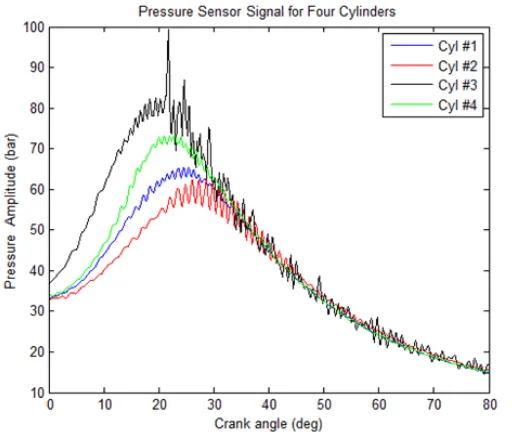
selected as the reference, and accuracy of knock detection based on mentioned method is measured based on cross correlation with this reference. Figure 2 shows sample of cylinder pressure sensor signal recorded from four cylinders in 5800(rpm) speed and 125% load. For knock intensity calculation from cylinder pressure sensor data, first the signal is band-pass fil-tered in the range of 4 to 40 kHz. After that, the filtered signal is rectified and the peak value of the rectified signal in a specified window, i.e. 10-80 Crank Angle after the cylinder top dead center (TDC) phase, is defined as the knock intensity of pressure sensor data for each engine cycle. All of cross correlation of this study investigated for 2200 sequential cycles.
The results of cross correlation for each of the decomposed components as well as some of their compounds (partial addition of IMFs) is obtained from knock sensor signal for 1st cylinder is shown in Table 2.
This result shows that the second and third IMFs have higher correlation. Despite the fact that some of the components have low cross correlation, each component has a part of the knock signal data. Therefore a weight is applied for each decomposed component according to equation (3).
The basic idea behind using weighed IMFs instead of normal knock intensity is the fact that the noise and signal are not uniformly shaped and therefore different IMFs has different signal to noise ratio, therefore by applying a weighting factor to different IMFs we can achieve higher signal to noise ratio.
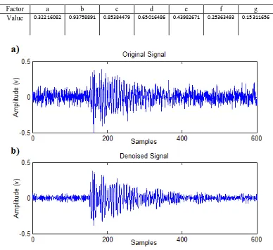
By using genetic algorithm, the coefficients were obtained for 1,000 cycles in order to achieve the highest cross correlation. Its results are shown in Table 3.
Figure 3 shows a sample result of this method for knock sensor signal. This signal clearly shows the expected characteristics of knock signal, it which vibration intensity decays with time.
Table 4 compares cross correlation with reference for both noisy knock (Normal) and denoised sig-nal with weighted EMD (WEMD) method in 5800(rpm) engine speed and 125% load for four engine cylinders.
As considered, this method has increased knock detection accuracy about 11.3% (based on ratio of average cross correlation of results).
The results of the genetic algorithm are consistent with our expectations and the weights of middle levels are higher than other levels, which means that the proposed method not only extracts the main frequencies of knock, but also assigns reasonable weights to them. As shown in Table 4, this method also provides appropriate results for new data from engine. Since that knock frequen-cies are always locate in the specified range of the frequency band, this method can be used for dif-ferent engine operating conditions. Also in order to perform more accurate analyses under different engine conditions, optimization based on genetic algorithm shall be performed under various oper-ating conditions and the results shall be stored in calibration table during calibration process to be used under real time
operating conditions
Fig 2. Pressure sensor signal for four cylinders in 5800(rpm) and 125% load.
Table 2. Cross correlation of IMFs and some of their compounds.
Table 3. Coefficients obtained for decomposed components.
Factor a b c d e f g
Value 0.32216082 0.93758891 0.85384479 0.65016486 0.43982671 0.25363493 0.15311656
Fig3. Sample result of proposed method for knock sensor signal a) Before denoising, s(t) b) After denoising,
Table 4. Cross correlation obtained for the four engine cylinders in the normal knock signal and after the application
of weighting EMD demising method.
Cylinder Number Method
1 2 3 4 Average CC
Normal 0.6184 0.6251 0.6618 0.5786 0.62098
WEMD 0.6826 0.6927 0.7213 0.6675 0.69103
IMFs 1 2 3 4 5 6 r ∑(2:3) ∑(2:4) ∑(2:5) ∑(3:4) ∑(3:5)
CC 0.25592 0.53503 0.46179 0.29845 0.21638 0.16926 0.13825 0.57011 0.52134 0.47230 0.49624 0.41227
4. Conclusion
EMD method is a highly adaptive and signal-depended method that is appropriate for non-stationary signals such as knock. In this study, this method was introduced and its results were analysed. Then, using genetic algorithm, appropriate weights were determined for signal decomposed components. Then the method was evaluated using signals recorded from 4 engine cylinders that increased the knock detection accuracy by 11.3%.
Ref
[1]. J.B. Heywood, "Internal combustion engine fundamentals", McGraw-Hill Book Company, New
York, 1988.
[2]. M. Castagno, J.P. Dumas, S. Henriot, F.A. Lafossas, "New knock localization methodology for
SI engines", SAE International Paper No. 2003-01-1118, (2003).
[3]. G. Derrico, T. Lucchini, S. Merola, C. Tornatore, "Application of a thermodynamic
model with
a complex chemistry to a cycle resolved knock prediction on a spark ignition optical engine", International Journal of Automotive Technology, vol. 13(3): p. 389-399, (2012). [4]. D. Kjellqviest, "Concept, strategy and controller
for gasoline engine management", M.Sc Thesis, Lulea University of Technology, (2005).
[5]. B. Iorio, V. Giglio and G. Police, "Methods of pressure cycle processing for engine control", SAE International Paper, 2003 01-0352, (2003). [6]. H. Noubari, and G. Dumont, "Towards an
improved knock detection and quantification using
wavelets and entropy-based noise compensation," SAE Technical Paper 2005-01-2269, (2005).
[7]. C. Hudson, X. Gao, and R. Stone, “Knock measurement for fuel evaluation in spark ignition engines,” FUEL, vol. 80: p.395-407, (2001).
[8]. A. Sanches, F. Pau, A. dos Santos, and J. da Silva, "identification and quantification of knock in internal combustion engines using spectral analysis" SAE Technical Paper 2001-01-3923, (2001).
[9]. A. Kenji, K. Hirotaka; K. Atsushi “Development of pattern recognition knock
detection system
using short time Fourier transform” ,7th IFAC Symposium on Advances in Automotive Control,
vol. 7: p. 366-71, (2013).
[10].S. Amboise, A. Ferrari, L. Galleani “In-cylinder pressure-based direct techniques and time frequency
analysis for combustion diagnostics in IC engines”, Journal of conversion and
management, vol. 99:
p. 299-312, (2015).
[11].A. Moshrefi, M. Shalchian, “Improved knock detection method based on time-frequency
analysis in spark ignition turbocharged engine”, Journal of Gazi Univertesi Gazi Egitim Fakultesi Dergisi, vol.04, no.04, (2015).
[12].S. T. Park, and J. Yang, “Engine knock detection based on wavelet transform” Proceedings of the 8th International Symposium on Science and Technology, IEEE MECHANICS, vol. 3: p. 80-83, (2004).
[13].L. Ren-jiang, Q. Dong-chao,S. Ying,L. Chun-mei, ”Noise reduction of wavelet transform for automobile engine knock signal”, Journal of Changchun University of Technology (Natural Science Edition), vol. 2, (2007).
[14].Z. Wu, N.E. Huang, “White noise using the empirical mode decomposition method”, Proceedings of the Royal Society of London. Series A: Mathematical, Physical and Engineering Sciences, vol. 460(2046):p.1597-1611, (2004).
[15].K.M. Chang, S.H. Liu, “Gaussian noise filtering from ECG by wiener filter and ensemble empirical mode decomposition”, Journal of Signal Processing Systems, vol. 64(2): p. 249-264, (2010).
[16].D.P. Lowe, T.R. Lin, W. Wu, A.C.C. Tan, “Diesel knock combustion and its detection using acoustic emission”, Journal of Acoustic Emission, vol. 29: p. 78-88, (2011).
[17].T. Bengisu, “Computing the optimum knock sensor locations”, SAE International Paper 2002-01-1187, (2002).