© Iranian Aerospace Society, Winter - Spring 2012
J
Journal ofA S T
Aerospace Science and TechnologyNomenclature
V Freestream Velocity (msec)
Cp (P-P)
P
q V!)
"Kgm3)
Re #!$
C %# &cm)
$ %'cm)
*t "%"+Deg.)
*w %"%"+(Deg.) ,* "%*t/*w (Deg.) 0W %1'"%
AR %"'#
Abbreviation
AOA Angle of Attack (Deg.) LE Leading Edge
PSD Power Spectrum Density
1 Introduction
Control surfaces are used in combat aircraft to control the pitching moment and to help the vehicle perform high angle of attack maneuvers. For delta wing problem more complicated. Many researches have been performed aimed at developing a practical method for
!"#$ % & -mation is presented to describe the importance and surfaces.
' in two different ways for aerodynamically controlled '( ' '-tion near the center of gravity as in the mid-wing con-')$
Effect of Wing Sweep Angle on The Vortex Interaction of a Tail-Wing
I. Bahman-Jahromi
1*+/
2**
3The goal of this investigation is to study the effect of wing sweep angle on of wind tunnel tests were conducted on a model having a moveable horizontal tail side of wing was measured for both static and dynamic changes of the tail angles ! " wing sweep angle is a dominant factor for the strength of the vortices over the
Keywords# $% &'%
V C
2
()* +,.$$/+0 1 "0 # 2
3.$/+0 1 -"0 # 2
4+ .1
2 I. Bahman-Jahromi, M.R. Soltani, and M. Masdari
Tail is the most useful control surface for long range ' ' % -most linear aerodynamic interferences is another factor ' attractive. Usually a constant wing is added to these ' )$
4 567 ' method can be expensive and time consuming even af-ter the exponential growth in the computational power -neering codes that can predict the aerodynamic angles of attack and Mach numbers. All of these codes are based on the wind tunnel tests.
An example of using Experimental data to validate +8$4& "" ::;$< -timated using a prediction code for a free stream Mach number of 1.7 and for a range of angle of attack from -2 to +18 deg. Comparison between the estimated and & +8$
+ @*7GH K$ 4 -neering codes have been validated for A.O.As up to 90 Q$ / 4& data are available for canard controlled models for both & X$ 4 also been validated with these experimental data. Da-halan [10] presents user friendly and in-house software " "" tail combinations.
Tests indicate nonlinearities associated with the vor-& ' G & "" Y most of the present engineering codes are not still ca-pable of an accurate prediction of the aerodynamic & moderate to high angles.
% and tail was tested in a subsonic wind tunnel. Variations of the surface pressure distribution on the wing with tested for wings with sweep angles of 30 and 60 degree <+\^8 the effects of wing sweep angle on the interaction were investigated. Tests were performed for both static and dynamic changes of the tail angle of attack at various &
2 Experimental Setup and Procedure
(
2.1 Wind Tunnel and Test Facility
Experiments were carried out in a subsonic closed cir-cuit wind tunnel with a closed test section of 0.8×0.8×2 m3. Figure 1 shows the wind tunnel and the test section. The maximum attainable speed in the test section is 100 m/s. Turbulence intensity of the wind tunnel is about 0.1%.
Surface pressure measurements were obtained by j! q -fully calibrated.
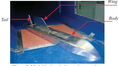
2.2 Model
( The angle of attack of the body and the tail can be var-ied independently. Fig. 2 shows the model installed in the test section of the aforementioned wind tunnel.
Figure 2. Model in the wind tunnel test section. %
Tail
Figure 1. Wind tunnel and the test section.
Tests were conducted for two different wings with ( #^ ;^ 6# presents different wings and tail geometry that were ;) -plied to plot the wing surface pressure contour.
In order to account for the possible errors in the -plied to the raw data to reduce the effects of electrical and mechanical noises and other sources of errors.
3 Results and Discussion
( |w\#^o |
w\;^ o.
w=30 o
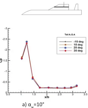
68 |w\#^ }w\!^ }w\!8 }w\~^when }\^ & be seen on the wing. Note that for this wing having a sweep angle of 30 the vortices unlike delta wings with leading edge sweep of 60 & type ones. A small part of the wing is affected by the &}w\!^ and the leading edge vortex covers a large portion of the wing suction surface by <G<@}wH
Figure 3. Wings and tail dimensions. y
x
y
x
y
x
2.3 Test Procedures
/ {\Q^ +\!;8!^6 @<& + to understand the physics of vortex interactions at the
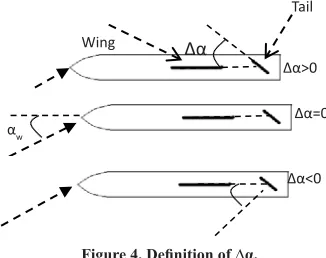
+ H }w\!^!8 and 20. Several tests were performed for static and dynamic oscillation of the tail < ~ wings with sweep angles of 30 and 60. An important parameter that was used in the results is the difference in the angle between the tail and the body-wing @}\}t"}wH6) } schematically.
Wing
Tail
w
w
w
w
w
w
w
wing.
) I. Bahman-Jahromi, M.R. Soltani, and M. Masdari
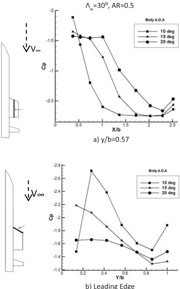
6 8 & -& } z }wY \^8K 6;
|w\#^ }w\~^.
Figure 7c shows that the pressure distribution over }w\~^ Y }w\~^@6;H6K }\^@}t\~^H }^@}t\#^H exists pressure suction associated with the vortex-type Y &
w
V
b) Leading Edge
V
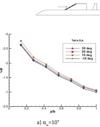
6 6 ; &" Y}w is & Y }w\!8 }w\~^. Fig. 6b & Y }w\!8 }w\~^. There exists a & Y }w\~^6;& }w\!^ is not located at the apex of the wing.
{ 5 Y edge in Fig. 7 to study the case better. The vortex on |w\#^ is weak and unstable at }w\~^6K
w
w
w
w
w
w
% } ^ }^ pressure distribution. To investigate the physics of this }\!^-tory of Cp at the apex of the wing is presented in Fig. 10. 66 & -}t\~^o}\^o and there is no vortex structure at }t\"!8o}\"#8o as expected from our previous analy-}t\#^o}\!^o the up wash related to the leading edge of the wing in a different manner. There seems to be a delay in the onset of leading edge vortex }t\#^o}\!^o.
The power spectral density function of the Cp is
ex-Figure 8. The path for body vortices.
path of the body vortices
w
}
V
}w\~^ } ^-tices that are generated by the body merge with each other down stream of the wing through the path that }w\~^ and & Y edge.
6X }w\~^ }\^@}t\~^H }\"#8@}t\"!8H |LE\#^. It is clearly seen that that }w\~^have
w
w
t
} ^ % 6 Q for the aforementioned phenomenon is schematically shown.
w
w
t
#$
Figure 10. Time history of Cp % w=20o.
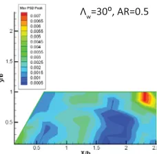
tracted from the Cp time history for the pressure channel located at the apex of the wing. Variations of the PSD for 6!!% -gation of the PSD plot indicates that the peaks of power }t\~^o}
w\~^
o
6 I. Bahman-Jahromi, M.R. Soltani, and M. Masdari
Figure 12 shows the power spectral density of the pressure channels at the leading edge of the wing when ^8 8}w\!8.
5 6!#68 -sociated with the leading edge vortex on the wing. affects almost the entire surface pressure over the wing }w\~^.
& w=60o
6!) |w\;^ }w\!^ !8 and 20 }\^ vortex can be seen over the wing surface. A small part &}w\!^ and the leading edge vortex covers a portion of the <G<}w. The vortex }w 6!)
Figure 11. Frequency analysis at the apex of the wing for different
PSD
Figure 12. PSD of the pressure Channels at leading edge of the wing for oscillating tail.
PSD
6 !~ which shows the kinetic energy is induced to the vortex & affected by the tail upwash.
It is very important to know which parts of the wing suction are most affected by the oscillating tail upwash. The PSD values of all pressure channels for an }w\!8 in Fig. 13.
Figure 13. PSD values for all channels at Įw=20, f=1/2 (Hz).
w
aH}w°
w
6 6!8 &" Y } }w\!^ }w\~^6!8 &" Y }& the leading edge of the wing is highly stable for these |w\#^@6;H
The effects of tail upwash on the wing surface 5\^8K associated with the static changes in the tail angle of }wY
w
bH}w °
w
c) }w
Figure 14. Cont’d.
z }Y \^8K 6!8
b) Leading Edge
Figure 15. Cont’d.
w
8 I. Bahman-Jahromi, M.R. Soltani, and M. Masdari
& -fected by the tail upwash for the corresponding angles }w\!^}w\!8 }w\~^. To study the 5 Y leading edge in Figure 17.
w
w
Figure 16. Cont’d.
c) }w
Figure 17. Cont’d.
& Y 6!K}^' Cp data for all y/b appears. Figure 18 shows time histo-5 Y }w\~^and }Y6 &}Y }t\"!^@}\"#^H }t\"~^@}\")^H5 6!Q the wing surface all the way thru the wing apex. One may think of this tail setting as an aerodynamic break which will cause the lift to deteriorate completely.
w
w
Figure 19 shows the contour of the surface pressure over the 60 }w\~^ }\")^. This & }\^6Y!)"!8 -&"
^8 6~^ which shows the kinetic energy induced to the vortex by & -lation can even affect the highly stable vortex structure over the 60 wing.
It is very important to know which parts of the wing suction surface are affected the most by the oscillating tail upwash. The PSD values of all pressure channels for 6~! }w\~^ 8.
*+9 : % w=20
o.
Figure 19. Contour of surface pressure on the 60 wing at Įw=20
"<>?).
Figure 20 shows the power spectral density of the pressure channel at the leading edge of the wing when 8}w\~^.
Figure 20. PSD of the pressure Channels at leading edge of the wing for oscillating tail.
% 5 & onset at the apex of the wing is the most affected 5 which is associated with the leading edge vortex on the wing.
Figure 22 shows the PSD of the pressure channel lo-cated at the apex of the wing when the tail is oscillating <G<% q/7 }w.
10 I. Bahman-Jahromi, M.R. Soltani, and M. Masdari
The reason for the aforementioned phenomenon is that the strength of body vortices increases by }w. Thus they cause more instability in the wing
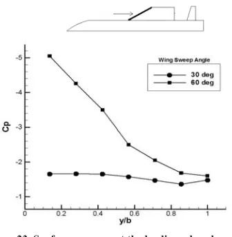
Figure 23 shows the static surface pressure at the leading edge channels of wings with sweep angles of 30 and 60}\~^ }\^
4 Conclusion
A series of wind tunnel tests were performed to leading edge vortex of two wings with different sweep " " % }w. The reason for this phenom-enon is that the vortices generated by the body merge with each other and make a strong instability at the }w. It was shown that % & #^ 6 & 6 ;^ on the leading edge vortex by the normal changes in the to the vortex strength and vortex stability. Note that the leading edge vortex strength and stability increases by increasing the wing sweep angle.
& } -& }\^ < } leading edge vortex formed over the wing surface. The }^ } ^ } ^ more instabilities at the wing downstream.
The tail upwash due to the Oscillation affects the wing surface pressure more than the case for the static % wash affects the places on the wing surface where the & pressure channel is the onset of the vortex at the wing &}w\~^. The effects of oscillating tail up wash }w.
5 References
1. 7 7 *64 GG< 7 < *5 /-5 4<++8~^/!XXK
2. 7 7 *64 G*6 q G q q <G +< AVT Spring 1998 Symposium on Missile q)/ %*!XXQ
3. 7 7 *64 6 q /5 5 * 6 / q 4<++ 8#^7!XXK
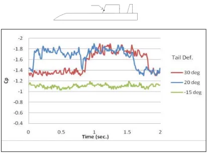
&&@BG' % " w for oscillating tail.
Figure 23. Surface pressure at the leading edge channels of all wings, w=20">
) 7 7 * * 7 G * 5 6 q % q K / < G /!XXQ
8 +< q%/ 4 Tool for Preliminary Aerodynamic Estimation of a 7+5 </ ~K~^^X
6. :<:z " % /-personic Speeds of a Canard-Controlled Missile z 6& 6"+ 6 </< q!#!;/!XKQ
7. + 4{ / * 7 6{4&5 < {~^Q;"X;~^^;
8. 4< *<*7 < -gle of Attack Aerodynamic Predictions Using Mis-7<%<<~^^8"8^Q; ~^^8
9. :<:/ < 5-actristics of a Maneuvering Canard – Controlled * 6& 6"+ 6 /<4qX^!XX#G!XX^