Please cite this article as: S. Jafarmadar, A. Jahangiramini, Numerical Simulation of Flash Boiling Effect in a 3-Dimensional Chamber Using Computational Fluid Dynamic Techniques, International Journal of Engineering (IJE), TRANSACTIONS A: Basics..Vol. 29, No. 1, (January 2016) 87-95
International Journal of Engineering
J o u r n a l H o m e p a g e : w w w . i j e . i rNumerical Simulation of Flash Boiling Effect in a 3-Dimensional Chamber Using
Computational Fluid Dynamic Techniques
S. Jafarmadar, A. Jahangiramini*
Department of Mechanical Engineering, Faculty of Engineering, Urmia University, Iran
P A P E R I N F O
Paper history: Received 01 March 2015
Received in revised form 31 December 2015 Accepted 05 January 2016
Keywords: Flash Boiling Numerical Simulation Bubble Nucleation Fuel Properties
A B S T R A C T
Flash-boiling atomization is one of the most effective means of generating a fine and narrow-dispersed spray. Unless its complexity, its potential has not been fully realized. In this paper, a three dimensional chamber has been modeled with a straight fuel injector. Effect of flash-boiling has been investigated by computational fluid dynamics (CFD) techniques. A finite volume approach with the standard k–ε turbulence model has been used to carry out all the computations. The dimensions of studied vortex tubes are kept the same for all models. Finally, some results of the CFD models are validated by the available experimental data which show reasonable agreement, and other ones are compared qualitatively. It is confirmed that flash-boiling effectively accelerates the atomization and vaporization of fuel droplets.
doi: 10.5829/idosi.ije.2016.29.01a.12
1. INTRODUCTION1
When a liquid, initially in a sub cooled state, is rapidly depressurized to a pressure sufficiently below the saturated vapor pressure, it can no longer exist in the liquid state, and a rapid boiling process called flash-boiling is initiated. Sudden evaporation of a portion of the fuel cools the rest of the liquid down and increases the spray volume.
In the case of high-pressure diesel injection, the phenomenon of flash-boiling can only be achieved if the fuel is sufficiently preheated before injection. In the case of gasoline injection, flash-boiling is much easier to obtain due to the lower boiling curve. Especially, if gasoline is injected to the intake manifold, where the static pressure can fall below the saturated vapor pressure of some hydrocarbon fuel components. Such a condition will result in unintended flash-boiling. This causes significant changes in the fuel spray distribution and the fuel-air mixing. Figure 1 shows the conventional and the flash-boiling fuel injection in a
1*Corresponding Author’s Email: [email protected] (A.
Jahangiramini)
pressure-enthalpy diagram. Subcooled liquid exists in the left of the liquid saturation line, and superheated vapor exists in the right of the vapor saturation line. By injection, the highly pressurized fuel leaves the nozzle’s orifice and during this process, the liquid is strongly accelerated and the pressure decreases. In the case of conventional injection (line 1’- 2’), because the fuel temperature, and its enthalpy is too low it cannot cross the liquid saturation line during pressure decrease.
Increasing fuel temperature results in a higher fuel enthalpy, so during injection the fuel undergoes a pressure reduction from point 1 to point 4 while passing through the nozzle orifice and flash-boiling occurs. After point 2 we have saturation condition and between this point and point 3, vapor bubbles are formed and begin to grow and beyond point 3 nucleation rates become large.
Numerous experimental studies of this injection type have been performed to examine the phenomenon in detail. Gerrish and Ayer [2] observed when diesel fuel was preheated prior to injection, spray cone angle increased. Kim et al. [3] confirmed that flash-boiling provides the benefits of the measurements of drop sizes, spray cone angle and penetration by performing flash-boiling studies with alcohol, in both an engine cylinder and a test chamber. Similar results were obtained by more fundamental experiments in atmospheric pressure chambers (e.g. [1-4]).
According to experimental investigations, depending on the degree of superheat; there are two main categories of flash-boiling sprays: external and internal flashing (e.g. [1, 5]). In the case of external flashing, evaporation and rapid bubble growth occurs outside the nozzle in the spray but in the case of internal flashing, rapid bubble growth occurs already inside the nozzle hole. The rapid bubble growth shatters the liquid jet and results in an increased spray cone angle and a reduced penetration, and bubble growth inside the nozzle hole results in an under-expanded compressible two-phase flow that expands immediately upon leaving the nozzle.
External flashing is difficult to obtain because a smooth nozzle entry geometry and/or low injection velocities must be used in order to avoid regions of locally low pressure inside the injection holes and to suppress internal flashing. Further on, careful matching of injection pressure and fuel temperature with combustion chamber pressure is necessary during the time of injection, because the degree of superheat and thus the change from the external to the internal flashing regime is very sensible to the chamber pressure. Hence, the relevant flashing regime is the internal flashing mode. However, internal flashing results in a reduction of effective cross-sectional area inside the injection hole and thus reduces the mass flow through the nozzle. At high degrees of superheat, the nozzle hole can become vapor-locked, and the mass flow reduces drastically [6]. In engine applications this has to be avoided in all cost.
Hence, the optimum degree of superheat is difficult to control, and this is one of the reasons why flash-boiling is not used today in series production engines. However, flash-boiling might become an important effect for future direct injection spark ignition (DISI) and homogeneous charge compression ignition (HCCI) engines because of the low gas pressures inside the combustion chamber during early injection.
An atomization model for superheated fuel sprays from pressure-swirl atomizers including the effect of flash-boiling has been recently developed by Zuo et al. [7]. It is assumed that under superheat conditions a hollow-cone spray sheet is still formed from the pressure-swirl atomizer, and the sheet flash-boiling is controlled by the rate of heat that can be conducted inside the sheet with an effective thermal conductivity. Hydrodynamic instability and cavitation sand bubble growth finally break the sheet up to form drops. Models for the subsequent drop vaporization account for heat transfer under flash-boiling and sub-boiling conditions.
Further models considering the effect of flash-boiling on spray atomization, including detailed nucleation and bubble growth models, are published, for example, by Fujimoto et al. [8], Kawano [9] and Zeng and Lee [10].The submodels for flash-boiling spray of multi component fuel which take accout for fuel properties, vaporization process, bubble nucleation, growth and disruption in multi component fuel droplet were solved with Fluent and added to KIVA3V. The numerical data using these models were compared with experimental data. The flashing spray characteristics from numerical simulation qualitatively showed good agreement with the experimental results. In addition the effects of initial fuel temperature on the numerical results are investigated.
2. MATHEMATICAL FORMULATION
negligible in this study. It is difficult to treat quantitatively the nucleation process due to fine dust or minute solid particles inside the liquid. Furthermore, fuel is well filtered for the experiments. Therefore, the nucleation due to dust is neglected in this study. Accordingly, only heterogeneous nucleation owing to dissolved gas as air is considered in this study. Regarding this process, it has been experimentally confirmed that the number density of bubble nuclei exponentially increased by the increase in the superheating degree for the superheated flash-boiling process [1, 12]. In general, it is assumed that the number density of bubble nuclei in the liquid N is constant throughout the fuel injection process in the above equation [13]. However, dissolved gas or air in the liquid is consumed by bubble nucleation. Therefore, it is supposed that N decreases as the time elapses in the nozzle orifice and droplets. It is reported that the number of bubble nuclei obtained by numerical simulation applied in this assumption agrees with the experimental data [14]. The number density N of bubble nuclei is approximately expressed by the following equation:
( ) {
( )} (1)
where ∆θ is the superheating degree of the liquid.
2. 2. Bubble Growth The bubble is assumed to grow spherically in nozzle orifice and droplets and the Rayleigh-Ples set equation [15] describes the growth process of the cavitation bubble. The growth rate of the cavitation bubble is controlled by hydrodynamics forces as follows:
̈ ̇ ( ) (2)
where ρ is the liquid density and Pr is the pressure around bubble. The fluid pressure at bubble surface, Pw, is defined by the following equation [16]:
( )( ) ̇ ̇ (3)
where Pv is the saturation pressure of fuel, Pr is the initial fluid pressure around bubble, R0 is the initial bubble radius , µl is liquid viscosity and κ is the surface
viscosity coefficient proposed by Scriven [17]. However, κ used in this equation has the value presented in the previous paper (κ=8.0×10⁻⁶ [N·s/m]) [16].
2. 3. Bubble Disruption There is a limit in the growth of bubbles inside droplet. This limit is determined by the diameter of the droplet, surface tension and liquid viscosity, then number density of bubble nuclei and growth rate.
The limit of bubble growth rate inside droplet is
provided with the void fraction, ε, defined by the volume ratio between the vapor and liquid phases as the following equation
:
(4)
where, Vbubble is volume of bubbles and Vliquid is volume of liquid. Suma et al. [18] mentioned that breakup of fuel jet occurred at
ε
=0.51 to 0.53 [18]. In this study, it is assumed that the droplet is broken up when the calculated void fraction reaches to 0.55, considering the apparent increase in the liquid viscosity of two-phase flow. Then, it is supposed that the droplet is broken up into small droplets twice as many as the number of bubbles, as illustrated in Figure 2.
As a consequence, both the number and diameter of droplets after breakup caused by bubble disruption can be calculated. The momentum of the parent droplet is uniformly distributed among the child droplets.
2. 4. Conservation Equation’s and Turbulence Formulation The governing equations are arranged by the conservation of mass, momentum and energy equations, which are given by:
(5) ( ) ( ̃)
(6) ( ) ( ̃ )
(7) [ ( ̃ ̃)]
[
( ) ]&
Since we assumed the working gas is an ideal gas, then the compressibility effect must be imposed so that:
(8)
Figure 2. Breakup caused by bubble disruption
The turbulence kinetic energy (k) and the rate of dissipation (ε) are obtained from the following equations:
(9) ( ) ( )
[( )
(10) ( ) ( )
[( )
] ( )
In these equations, Gk, Gb, and YM represent the generation of turbulence kinetic energy due to the mean velocity gradients, the generation of turbulence kinetic energy due to buoyancy and the contribution of the fluctuating dilatation in compressible turbulence to the overall dissipation rate, respectively. C1ε and C2ε are
constants. σk and σε are the turbulent Prandtl numbers for k and ε also. The turbulent (or eddy) viscosity, µt, is computed as follows:
(11)
where, Cμ is a constant. The model constants C1ε, C2ε, Cμ, σk and σε have the following default values: C1ε = 1.44, C2ε = 1.92, Cμ = 0.09, σk = 1.0, σε = 1.3.
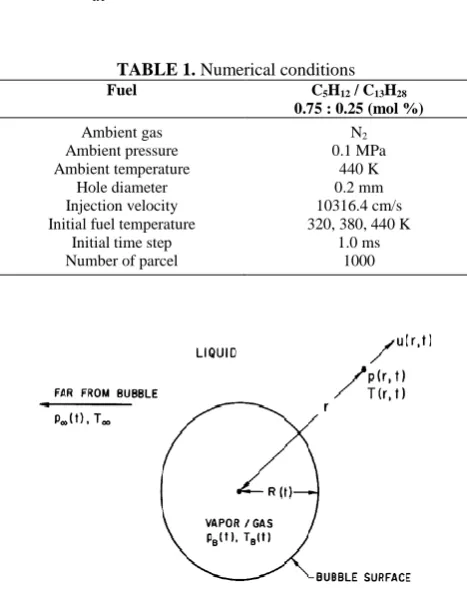
Finite volume method with a 3D structured mesh is applied to the mentioned governing equations. Table 1 summarizes the conditions for the numerical simulation. As a fuel, the mixture of 75 mol% n-pentane (C5H12)
and 25 mol% n-tridecane (C13H28) was used. Initial
ambient temperature and pressure were 440 K and 0.1MPa, respectively. Initial fuel temperature Tf was varied to 320, 380 and 440 K for the control of flash boiling process. Injection velocity of 10316.4 cm/s was calculated from Bernoulli’s equation in order to correspond to 15 MPa of injection pressure. Second order upwind scheme is utilized to discretize convective terms, and SIMPLE algorithm is used to solve the momentum and energy equations simultaneously.
2. 5. Bubble Dynamics Equation: Rayleigh-Plesset Equation Consider a spherical bubble of radius, R (t) (where t is time), in an infinite domain of liquid whose temperature and pressure far from the bubble are T and p (t), respectively. The temperature, T, is assumed to be a simple constant since temperature gradients were eliminated, a priori and uniform heating of the liquid due to internal heat sources or radiation will not be considered. On the other hand, the pressure, p (t), is assumed to be a known (and perhaps controlled) input which regulates the growth or collapse of the bubble.
Though compressibility of the liquid can be important in the context of bubble collapse, it will, for the present, be assumed that the liquid density, ρL, is a constant. Furthermore, the dynamic viscosity, νL, is assumed constant and uniform. It will also be assumed that the contents of the bubble are homogeneous and that the temperature, TB (t), and pressure, pB (t), within the bubble are always uniform. These assumptions may not be justified in circumstances that will be identified
as the analysis proceeds.
The radius of the bubble, R(t), will be one of the primary results of the analysis. As indicated in Figure 3, radial position within the liquid will be denoted by the distance, r, from the center of the bubble; the pressure, p(r,t) , radial outward velocity, u(r,t), and temperature, T(r,t), within the liquid will be so designated. Conservation of mass requires that
( ) ( ) (12)
where F(t) is related to R(t) by a kinematic boundary condition at the bubble surface. In the idealized case of zero mass transport across this interface, it is clear that u(R,t)=dR/dt and hence:
( )
(13)
TABLE 1. Numerical conditions
Fuel C5H12 / C13H28
0.75 : 0.25 (mol %)
Ambient gas Ambient pressure Ambient temperature
Hole diameter Injection velocity Initial fuel temperature
Initial time step Number of parcel
N2 0.1 MPa
440 K 0.2 mm 10316.4 cm/s 320, 380, 440 K
1.0 ms 1000
Figure 3.Schematic of a spherical bubble in an infinite liquid.
Therefore:
( ) ( ) [ ( )] (14)
and
( ) [ ( )]
(15)
In many practical cases ρV(TB) ρL and therefore the approximate form of Equation (13) may be adequate. For clarity we will continue with the approximate form given in Equation (13).
Assuming a Newtonian liquid, the Navier-Stokes equation for motion in the r direction yields after substituting for u from u=F(t)/r2:
[ (
)
] (16)
(17)
Note that the viscous terms vanish; indeed, the only viscous contribution to the Rayleigh-Plesset Equation comes from the dynamic boundary condition at the bubble surface. Equation (16) can be integrated to give:
(18)
Finally Rayleigh-Plesset equation for bubble dynamics generalized as bellow:
( ) ( )
( ) (19)
It was first derived and used by Rayleigh (1917). Plesset (1949) first applied the equation to the problem of traveling cavitation bubbles.
3. PHYSICAL MODELING
Figure 4 shows the computation algrid for this computation. This gridis assumed a circular cylinder shaped constant volume vessel which is 100 mm in height and 60 mm in diameter. Nozzle modeled as a hole on top of the cylinder with 0.2 mm in diameter. The geometry of the model and present created CFD model is identical to the experimental data’s of Kawano et al. [19]. In this numerical research, all geometrical properties of the Kawano et al. [19] model are kept constant and effect of flash-boiling was investigated under different kinds of fuels and temperatures. The 3-D CFD model with refinement in mesh along with boundary regions is shown in Figure 4. Boundary conditions for the models are determined based on the experimental measurements by Kawano et al. [19]. The inlet is modeled as a velocity inlet. Mechanism of injection can be changed with its inlet parameters. In addition, a no-slip velocity boundary
condition is enforced on all of the walls of vortex tube, and simultaneously they are assumed to be adiabatic.
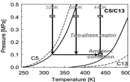
Figure 5 shows the effect of initial fuel temperature variations on pressure-temperature diagram for the mixed fuel. In this case, it is peculiar that “two-phase region” which has both liquid and vapor phases appears on this diagram. In this diagram, upper and lower borderlines of the two-phase region correspond to the saturation liquid and vapor lines, respectively. Furthermore, it is easy to obtain the flash-boiling effect using a mixture, because the critical point of the mixture is shifted to higher pressure side, compared to each single component fuel. The conditions of the fuel which is injected into the combustion chamber at each initial fuel temperature established in this study are represented in this figure as the bold line. The state at Tf=320 K is just on the saturation liquid line of the two-phase region. In case of Tf=380 and 440 K, the mixed fuel directly passes through the two-phase region crossing saturation liquid line during decompression process and decompression degree (= saturation pressure – ambient pressure) is enhanced with increases in Tf. Especially, in case of Tf=440 K, mixed fuel can be directly reached to ambient condition by only decompression process.
Figure 4.Three-dimensional CFD model of chamber
Figure 6.Grid size independence study at different average unit cell volumes.
5. RESULTS AND DISCUSSIONS
5. 1. Grid Independence Study The 3-D CFD analysis has been carried out for different average unit cell volumes in chamber as a computational domain. This is because of removing probable errors arising due to grid coarseness. Hence, first the grid independence study has been accomplished for inlet temperature of 320 K. The spray tip penetration in 1ms after injection as the key parameter is shown in Figure 6 for different unit cell volumes. Not much significant advantage can be seen by reducing the unit cell volume size below 0.8 mm3; which corresponds to 371100 cells. The same type of unit cell volume of grids is used to study the introduced chamber.
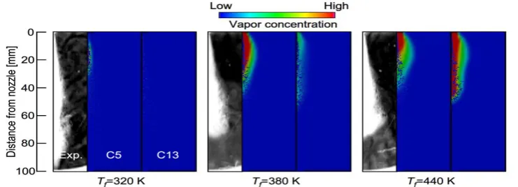
5. 2. Droplet and Vapor Distributions Figure 7 shows the droplet and vapor distributions for each initial fuel temperature at time from start of injection tinj=1.0 ms. In this figure, shadow graph images which are obtained by the previous experiment using constant
volume vessel [19] are added. In case of Tf=320 K at which flash-boiling does not occur, n-tridecane does not almost vaporize. The state of the fuel lies on saturation liquid line as can be seen in Figure 4. Even then, n-tridecane cannot evaporate, because the ambient temperature is comparatively low and it is not easy to heat up liquid droplets.
Both n-pentane and n- tridecane well vaporize at Tf=380 K at which flashing occurs. High vapor concentration region of n-pentane is located at upstream of fuel spray. On the other hand, the fuel spray also has high vapor concentration region of n-tridecane at the downstream. It is reported that vaporization process of multicomponent fuel depends on batch-distillation from the result of spray experiments [20, 21].
The batch-distillation of multicomponent fuel spray is maintained in spite of flashing or non-flashing. The trend in the batch- distillation at Tf=440 K becomes more remarkable and both n-pentane and n- tridecane actively vaporize because of violent flashing due to large decompression degree.The spray widths at Tf=380 and 440 K obtained from gas phase in numerical results seem to be much larger than the experimental one. However, it was observed that, in case of Tf=380 and 440 K, lean mixture disperses to radial direction near nozzle orifice [19]. This dispersion cannot be clearly observed in Figure 5. It can be thought that this phenomenon is occurred by violent flashing, since it is not possible to observe that at Tf=320 K. Therefore, the drastic increase in spray width due to flashing can be predicted using this model.
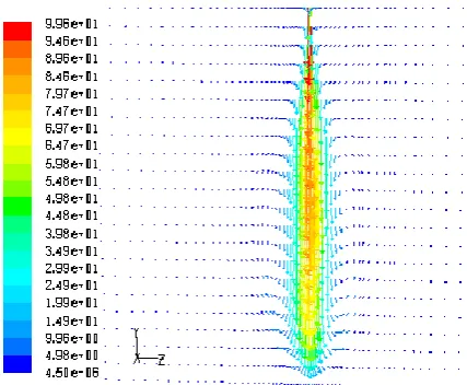
Velocity vectors colored by their magnitude is shown in Figure 8 to consider exact flow pattern in injection process in caseof Tf=320 K and Tf=380 K. The spray widths at Tf=380 and 440 K obtained from gas phase in numerical results seem to be much larger than the experimental one. However, it was observed that, in case of Tf=380 and 440 K, lean mixture disperses to radial direction near nozzle orifice [19].
Figure 7. Droplet and vapor distributions for each initial fuel temperature at time from start of injection tinj=1.0 ms.
66 68 70 72 74 76 78 80 82
0.75 0.85 0.95 1.05 1.15 1.25
Spra
y
Ti
p
Penet
rat
ion
(m
m
)
in
1m
s
Average Unit Cell Volume (mm3 )
Figure 8 a.Velocity vectors in case of Tf=320 K
Figure 8 b.Velocity vectors in case of Tf=380 K
Figure 9. Fuel penetration
This dispersion cannot be clearly observed in Figure 5. It can be thought that this phenomenon occurs by violent flashing, since it is not possible to observe that at Tf=320 K. Therefore, the drastic
increase in spray width due to flashing can be predicted using this model. Velocity vectors colored by their magnitude is shown in Figure 8 to consider exact flow pattern in injection process in case of Tf=320 K and Tf=380 K.
5. 3. Fuel Penetration Figure 9 indicates the experimental and numerical results of fuel penetration. In case of Tf=320 K, fuel linearly penetrates up to impingement on the wall. Nevertheless, numerical fuel penetrations of Tf=320 K are slightly longer than the experimental one. In this model, the parameters in droplet break up model (TAB model) are optimized to approximate the under estimated droplet size derived from the original TAB model to real droplet size of diesel spray [22]. Therefore, it is estimated that this improvement produces large droplets and the fuel penetration is overestimated, especially under low ambient pressure. On the other hand, numerical fuel penetrations of Tf=380 and 440 K are shorter than that at Tf=320 K due to flash-boiling as can be seen from Figure 6. The penetration trace at Tf=440 K is similar to that at Tf=380K in spite of the different decompression degree, and this trend can be seen from the experimental data. It is estimated that penetration at Tf=440 K is made longer by droplet cooling effect of much latent heat of vaporization. Therefore, this model can correctly predict the short fuel penetration of flashing spray.
6. CONCLUSION
From the numerical investigation of the effect of flash-boiling on spray characteristics of multicomponent fuel, the following conclusions are obtained.
Flash-boiling processes (bubble nucleation, growth and disruption) in multicomponent fuel droplets and nozzle orifice are modeled.
In case of Tf=380 K, batch-distillation which is peculiar to multicomponent fuel is observed, and especially this trend becomes more remarkable at Tf=440 K.
The fuel linearly penetrates up to impingement on the wall at Tf=320 K. The numerical fuel penetrations of Tf=380 and 440 K are shorter than that at Tf=320 K due to flash-boiling. This trend agrees with experimental data.
In case of Tf=320 K, both pentane and n-tridecane do not vaporize. On the contrary, both components completely vaporize after tinj=1.0 ms at Tf=440 K.
is drastically shifted to small droplet side due to flashing, compared with that at Tf=320 K.
7. REFERENCES
1. Oza, R.D. and Sinnamon, J.F., An experimental and analytical study of flash-boiling fuel injection., SAE Technical Paper. (1983)
2. Gerrish, H.C. and Ayer, B.E., "Influence of fuel-oil temperature on the combustion in a prechamber compression-ignition engine", NACA Technical Note (1936), 565-577 3. Kim, Y., Iwai, N., Suto, H. and Tsuruga, T., Improvement of
alcohol engine performance by flash boiling injection. JSAE Review, No 2, (1980) 81–86.
4. Wu, K., Steinberger, R. and Bracco, F., "On the mechanism of breakup of highly superheated liquid jets", Paper No. CSS/CI, , (1981), 81-17.
5. Park, B.S. and Lee, S.Y., "An experimental investigation of the flash atomization mechanism", Atomization and Sprays, Vol. 4, No. 2, (1994) 102-134.
6. Reitz, R.D., "A photographic study of flash-boiling atomization", Aerosol Science and Technology, Vol. 12, No. 3, (1990), 561-569.
7. Zuo, B., Gomes, A. and Rutland, C., "Modelling superheated fuel sprays and vaproization", International Journal of Engine Research, Vol. 1, No. 4, (2000), 321-336.
8. Fujimoto, H., Mishikori, T., Tsukamoto, T. and Senda, J., "Modeling of atomization and vaporization process in flash boiling spray", ICLASS-94, Paper VI-13,, (1994) 36-49. 9. Kawano, D., Ishii, H., Suzuki, H., Goto, Y., Odaka, M. and
Senda, J., "Numerical study on flash‐boiling spray of multicomponent fuel", Heat Transfer—Asian Research, Vol. 35, No. 5, (2006), 369-385.
10. Zeng, Y. and Lee, C.-F.F., "An atomization model for flash boiling sprays", Combustion Scienceand Technology, Vol. 169, No. 1, (2001), 45-67.
11. Sato, K., Lee, C. and Nagai, N., "A study on atomization process of superheated liquid", Transactions of JSME (B), Vol. 50, No. 455, (1984), 1743-1752.
12. Nakamura, K. and Someya, T., "Investigation on the tensile strength of real liquids", Transactions of JSME (B), Vol. 46, No. 405, (1987), 910-917.
13. Van Stralen, S. and Cole, R., "Boiling phenomena: Physicochemical and engineering fundamentals and applications, Hemisphere Pub.(Washington), Vol. 2, (1979). 104-142 .
14. Adachi, M., McDonell, V.G., Tanaka, D., Senda, J. and Fujimoto, H., Characterization of fuel vapor concentration inside a flash boiling spray., SAE Technical Paper (1997) 15. Plesset, M. S., Cavitation in Real Liquids, Amer. Elsevrer
Pub. (New York), (1964) 1-14.
16. Ida, T. and Sugiya, T., "Motion of air bubbles in mineral oils subject to sudden change in chamber pressure (1st report, experimental analysis for single bubbles)(in japanese)",
Transactions of JSME 45–399, (1979), 1650-1657.
17. Scriven, L., "Dynamics of a fluid interface equation of motion for newtonian surface fluids", Chemical Engineering Science, Vol. 12, No. 2, (1960), 98-108.
18. Suma, S. and Koizumi, M., "Internal boiling atomization by rapid pressure reduction of liquids", Transactions of the Japanese Society of Mechanical Engineers, Vol. 43, No. 376, (1977), 4608-4617.
19. Kawano, D., Azechi, N., Senda, J. and Fujimoto, H., “Spray Characteristics of Multicomponent Fuel”, The 10th International Symposium on Flow Visualization, F0219, (2002) 65-72.
20. Akihama, K., Fujikawa, T. and Hattori, Y., "Simultaneous laser-induced fluorescence measurements of in-cylinder fuel behavior of different boiling point components", in Proc. 15th Internal Combustion Engine Symposium (International), Seoul. (1999), 577-582.
21. Styron, J.P., Kelly-Zion, P., Lee, C.-F., Peters, J., White, R.A. and Lucht, R., Multicomponent liquid and vapor fuel distribution measurements in the cylinder of a port-injected, spark-ignition engine., SAE Technical Paper. (2000), 87-96 22. Kawano, D., Senda, J., Wada, Y., Fujimoto, H., Goto, Y.,
Numerical Simulation of Flash Boiling Effect in a 3-Dimensional Chamber Using
Computational Fluid Dynamic Techniques
S. Jafarmadar, A. Jahangiramini
Department of Mechanical Engineering, Faculty of Engineering, Urmia University, Iran
P A P E R I N F O
Paper history: Received 01 March 2015
Received in revised form 31 December 2015 Accepted 05 January 2016
Keywords: Flash Boiling Numerical Simulation Bubble Nucleation Fuel Properties
هديكچ
دنيارف نيا يياناوت نآ يگديچيپ فلاخرب دشاب يم يرپسا ديلوت رد مهم ياهدنيارف زا يكي عيرس ششوج شور هب نويسازيمتا
هظفحم كي ،يسررب نيا رد .تسا هدشن فشك يبوخ هب نونكات 3
سم تخوس لزان كي اب يدعب .تسا هديدرگ يزاسلدم ميقت
يريگراكب اب دودحم مجح شور كي و هدش هعلاطم يتابساحم تلاايس كيمانيد شور زا هدافتسا اب عيرس ششوج هديدپ ريثات
سنلاوبروت درادناتسا لدم k–ε
لدم داعبا .تسا هدش يريگراكب تلاداعم لح يارب ناسكي تلااح يمامت يارب هدش هتخاس ياه
هدش هتفرگ رظن رد تياضر لصاح هجيتن و هسياقم دوجوم يبرجت ياهراك جياتن اب لصاح يددع راك جياتن تياهن رد .تسا
تارطق ريخبت و نويسازيمتا ًاديدش عيرس ششوج هديدپ هك دشاب يم تيعقاو نيا هدنهد ناشن لصاح يسررب .دشاب يم شخب
.دهد يم باتش ار تخوس
![Figure 1 .Comparison of conventional injection and flash-boiling injection [1]](https://thumb-us.123doks.com/thumbv2/123dok_us/221242.2016644/1.595.346.506.565.687/figure-comparison-conventional-injection-flash-boiling-injection.webp)