Please cite this article as: A. Goudarzian, H. Nasiri, N. Abjadi, Design and Implementation of a Constant Frequency Sliding Mode Controller for a Luo Converter, International Journal of Engineering (IJE), TRANSACTIONS B: Applications Vol. 29, No. 2, (February 2016) 202-210
International Journal of Engineering
J o u r n a l H o m e p a g e : w w w . i j e . i rDesign and Implementation of a Constant Frequency Sliding Mode Controller for a
Luo Converter
A. Goudarzian*, H. Nasiri, N. Abjadi
Faculity of Engineering, Shahrekord Univercity, Shahrekord, Iran
P A P E R I N F O
Paper history:
Received 19 May 2015
Received in revised form 08 September 2015 Accepted 26 January 2016
Keywords: POESLL Converter
Constant Frequency Sliding Mode Controller Laboratory Prototype
A B S T R A C T
In this study, a robust controller for voltage regulation of a POESLL converter operated in continuous conduction mode is presented. The POESLL converter is a DC/DC converter with a high voltage gain. DC/DC converters are used in telecommunication systems, power sources and industrial applications. Owing to the switching operation, the structure of the POESLL converter is non-linear. In addition, because of the load and input voltage variations, the structure of the POESLL converter is time-varying. In order to regulate the output voltage of the POESLL converter, a non-linear controller is required. The proposed controller is developed based on constant frequency sliding mode method. The sliding mode controllers can cope with the non-linear and time-varying structure of the DC/DC converters. The performance of the proposed controller is studied in PSIM software. A laboratory model of the proposed controller has been implemented. In this paper, design, simulations and experimental results are presented to show the effective performance of the proposed controller for voltage regulation of the POESLL converter.
doi: 10.5829/idosi.ije.2016.29.02b.09
1. INTRODUCTION1
Nowadays, DC/DC converters are widely used in industrial applications [1, 2]. Theoretically, the conventional DC/DC converters such as boost, cuk, buck-boost, zeta and sepic can be used to increase the output voltage. However, in practical conditions, the voltage gain of the DC/DC converters is limited because of the parametric effects and inductor coil saturation. In addition, high increment in the output voltage increases switching losses.
The super lift (SL) method has been widely used in the design of DC/DC converters [3]. In this method, voltage gain of DC/DC converter increases in geometric progression. The positive output elementary super lift Luo (POESLL) converter has been designed based on super lift method. The POESLL converter is an attractive topology with a high voltage gain. In the same operating conditions, the inductor average current of the POESLL converter is less than the inductor average current of other conventional DC/DC converters. The
*Corresponding Author’s Email: [email protected] (A. Goudarzian)
inductor current is limited because of the inductor coil saturation problem. Therefore, the POESLL converter is a suitable candidate for power systems. The structure of the POESLL converter is non-linear and time-varying. To overcome these problems, a non-linear controller with robust performance is needed.
The signal flow graph (SFG) method has been widely used for modeling DC/DC converters [4, 5]. The design based on SFG method is simple; however, some dynamic characteristics are averaged out in the model of DC/DC converter. It attenuates the performance of the converter against parametric variations. The small signal sliding mode method for DC/DC converters has been introduced in [6]; however, this controller is designed in a specific operating point.
backstepping methods [12]; However, implementation of these controllers may be expensive and complicated. The sliding mode controller (SMC) is a type of non-linear controller. It is used for both non-linear and non-non-linear systems [13]. This control ensures stability of the POESLL converter in a wide range of operating conditions. In addition, the implementation of SMC is simple compared with other non-linear controllers. It is shown that the SMC is a possible solution for enhancing the performance of DC/DC converters [14, 15].
The traditional SMCs are developed by applying the hysteresis method (HM) [16-18]. In [19], a HM based SMC has been presented for output voltage regulation of the POESLL converter. In [20], current control for paralleled POESLL converters using HM based SMC has been introduced. In [21], a fuzzy logic controller-HM based SMC has been reported for DC/DC converters. These studies have shown the robust performance of the SMC; however, the HM based SMC has a major disadvantage. In this method, the switching frequency of DC/DC converter is variable, because of the hysteresis modulation. The variable frequency will result in noise and electromagnetic interference problems, inductor losses and large switching losses. In addition, it makes the design of the input and output filters more complicated. The constant frequency sliding mode method has been presented [22-24], which has these major disadvantages: difficulty in design and implementation and requiring more sensors and more calculations.
In this paper, design and implementation of a constant frequency SMC for a POESLL converter operated in continuous conduction mode are presented. This method is developed based on the equivalent control approach. In this method, an appropriate sliding surface S is defined. Then, an equivalent control law ueq is derived in terms of the state variables of the converter by solving S. 0. Consequently, the defined sliding surface is indirectly enforced to reach the origin (S=0). In practice, in the implementation of the constant frequency sliding mode controller, the control law ueq is constructed using a pulse width modulator. In this paper, the model of POESLL converter is derived. Then, the constant frequency SMC is designed. The performance of the proposed controller for POESLL converter is studied in different operating conditions. The analogue implementation of the proposed system is a useful contribution for researchers. The design of the constant frequency sliding mode controller is done using the reduced order equations of the POESLL converter. The advantages of this method are: less computations and less number of sensors [25].
This paper is organized as follows: In section 2, the average model of POESLL converter is derived and the performance of the converter is studied. In section 3, design of the proposed controller is done. The simulations and experimental results of the proposed
system at various operating points are discussed in section 4. Finally, the conclusions are listed in section 5.
2. MODEL OF A POESLL CONVERTER IN CONTINUOUS CONDUCTION MODE
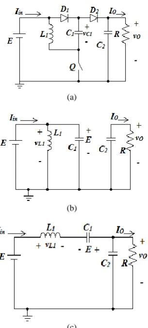
The diagram of the POESLL converter is shown in Figure 1(a). The output voltage increment can be performed by controlling the duty cycle of the switch. The POESLL converter is constituted of two diodes D1, D2, two capacitors C1, C2, inductor L and power switch Q. In Figure 1(a), R and E are load and input voltage, respectively. iL is inductor current, vC1 capacitor (C1) voltage and vO is output voltage. It is supposed that the POESLL converter operates in continuous conduction mode and components of the converter are ideal. The circuit operation of the POESLL converter is studied in two conditions: The switch-ON condition and the switch-OFF condition. Figures 1(b) and (c) show these two conditions.
In switch-ON state, diode D1 and switch conduct. Diode D2 is OFF. The inductor current (iL) is charged with slope E/L and capacitor C1 is charged by input voltage. The load energy is provided by output capacitor.
In switch-OFF state, diode D1and switchare OFF and diode D2 conducts. The inductor current is discharged with slope (2E-vO)/L. In this state, inductor L and capacitor C1 provide the output energy. The capacitor voltage vC1 is fixed with the assumption that the capacitor value C1 is large enough. Therefore, the following relation is obtained for all times:
C1( ) E
v t (1)
Using (1), the averaged model of the POESLL converter is expressed as (2).
2
1
1
L
O
O
L O
di
L E u E v
dt
dv
C u i Gv
dt
(2)
where u ε (0, 1)
3. COMPARISION BETWEEN THE POESLL
CONVERTERAND OTHER CONVENTIONAL
CONVERTERS
2
in L
I I
u (3)
In ideal conditions, PO=Pin then the relation between inductor average current and output average current is:
1 2
L O
in o in O O
O
I V
P P EI V I G
I E u (4)
where G=VO/E in steady state region.
The relation between inductor average current and output average current for other conventional DC/DC converters is obtained as (5).
, , ,
1 Buck-boost
L O L O
I
G For Boost Cuk Sepic Zeta
I
I
G For
I
(5)
A plot of IL/IO versus G is shown inFigure 2. It is clear that the inductor average current of the POESLL converter is less than that of other converters.
(a)
(b)
(c)
Figure 1. Diagram of the POESLL converter (a) Topology of the POESLL converter (b) POESLL converter in switch-ON condition (c) POESLL converter in switch-OFF condition
Figure 2. Plot of IL/IO versus G for DC/DC converters
4. DESIGN OF CONSTANT FREQUENCY SMC FOR THE POESLL
The SMC is flexible in design and simple in implementation. All the state variables of the converter can be sensed to generate the sliding surface, which enhance the performance of the SMC; however, this method makes the design of the controller more complicated [22-24]. It is worthwhile to note that complexity in the design of the sliding mode controller can be reduced by selecting a proper sliding surface. In this paper, the reduced order model of the converter is used to design the SMC. Therefore, only iL and vO are sensed to generate sliding surface. These variables are sufficient to regulate the output voltage of the converter. Here, the sliding surface of the POESLL converter is expressed as:
L O O d
S ai bv c βv V (6)
where a, b, c are controller parameters, Vd is the output voltage reference and β is a positive constant. In steady state region, βVO=Vd. The presence of integral term of the output voltage reduces the output voltage error in steady state region [7]. Using Equations (2) and (6), the derivative of the sliding surface is obtained as:
2 2
1 O C
O d
a u E v
aE bi
S c v V
L L C (7)
The equivalent control law is obtained by solving S 0.
It can be written as:
1 2 2 3
1
2 O C O d
eq
O
k E v k i k v V
u
k E v (8)
where:
1 2 3
2
, ,
a b
k k k c
L C (9)
stability of the closed loop system: eexistence condition, reaching condition, stability condition {Tan, 2007 #23;Tan, 2008 #25;He, 2010 #26}.
4. 1. Existence Condition This condition ensures the existence of the sliding mode operation. The existence condition determines the acceptable range of the controller coefficients. This condition guarantees that all phase trajectories of the controller in the phase portrait are directed toward the sliding surface. It is expressed as Equation (10).
0 0 lim 0 lim 0 S S S S (10)
when S 0, S<0, u=1 then:
2 2 0 C O d aE bi
S c v V
L C (11)
when S 0, S>, u=0 then:
2 2
0
O C
O d
a E v
aE bi
S c v V
L L C (12)
The existence condition is expressed as:
max 2 max
2 min 2 min
2 2 0 0 omax C Omax d C Omin d
aE av bi
c v V
L L C
aE bi
c v V
L C
(13)
4. 2. Reaching Condition
This condition guarantees that all the state variables of the system reach the origin (S=0) from any initial condition.
u 0 t
u 1 t
lim | 0
lim | 0
S
S (14)
This condition is satisfied by appropriate selection of the controller coefficients shown in (13) using the existence condition.
4. 3. Stability Condition The stability condition ensures that the states errors of the POESLL converter are kept on the origin (S=0). For the constant frequency SMC, this condition is checked by determining the state space equations of the closed loop system and then small signal analysis around their equilibrium points.
4. 3. 1. State Space Equations of the Closed Loop System The dynamic equations of the POESLL converter under the constant frequency SMC are obtained by replacing ueq in (2) with (8) which yields:
1 2 2 3 1
1 2 2 3 2
1
c O d
L
O O
c O d
o O
L O
k E k i k v V
di
L E E v
dt k E v
k E k i k v V
dv v
C i
dt k E v R
(15)
4. 3. 2. Equilibrium Points of the POESLL Converter Suppose that all conditions are satisfied. In origin (S=0), all the state variables of the converter reach the equilibrium points; that is, dvO/dt=diL/dt =0. Then, the equilibrium points of the converter are expressed as:
d O d d L V V β
V V E
I RE
(16)
In (16), VO, Vd and IL are output voltage, voltage reference and inductor current in steady state region, respectively. R and E are output resistance and input voltage.
4. 3. 3. Small Signal Analysis of the Dynamic Equations Equation (15) can beexpressedas (17). By using the following static condition βVO-Vd=0 and the assumption VO>>Vd; then, the linearized equations of the closed loop system can be given as (18).
L L 1 2 O O
1
3 O O 4 2 O O
1
O O 1 2 O O
2
1 O O
3 O O 4 2 O O
O O 1 O O
d I i a E+a α(V v v )
L E
dt a
a α V v v dt+a C d V v / dt
a
d V v a E a α(V v v )
C
dt a E V v
a α V v v dt+a C d V v / dt V v
R
a E V v
d d d d (17) L
11 L 12 O
O
21 L 22 O
d i
b i b v dt
d v
b i b v dt (18) where: 2 11 2 1 2
3 3 2
12
2
1 1 1 2
1 1 21
2 1 2
1 22
2 1 2
2 / / 2 / d d d d d d d d d d d d k E b k V
L E V k
RE
k V E
k k k V
b
k V
Lk Lk k k V RE RE
L E V k R
RE k E b
C E V k k V RE
k V E
b
C E V k k V RE R
The characteristics equation of the linearized closed loop system is written as Equation (20).
11 12 2
1 2
21 22
0
S b b
S d S d
b S b (20)
where:
1 11 22, 2 11 22 12 21
d b b d b b b b (21)
According to Routh criterion, the following conditions must be satisfied to ensure the closed loop stability of the linearized system.
1 0, 2 0
d d (22)
By mathematically solving Equation (19) and replacing into Equation (22), the stability of the closed loop system is determined; then, by using Equation (13) and observing the output voltage response, the proper range of the controller coefficients can be given.
5. SIMULATION AND EXPERIMENTAL RESULTS
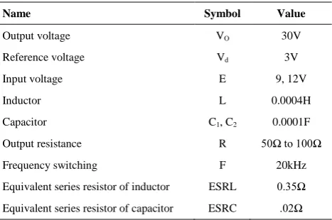
In this section, simulations and experimental results are presented to show the effectiveness of the proposed sliding mode controller for a POESLL converter operated in continuous conduction mode. The coefficients of the proposed controller are selected as: k1=0.015, k2=0.02, k3=0.1, β=0.1. The circuit parameters of the POESLL converter are listed in Table 1. The simulations have been performed in PSIM software. The circuit elements of the converter are listed in Table 2.
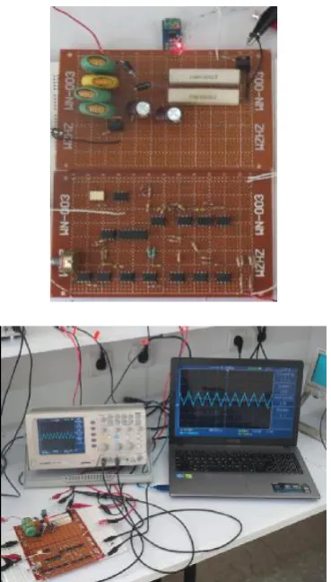
The laboratory model of the POESLL converter under the proposed controller is shown in Figure 3. The proposed system has been implemented in analogue platform. From Figure 3, it can be seen that the equivalent control law is implemented using Op- Amps; then, it is compared with a saw tooth waveform to generate the switching signal. The obtained signal is given to the switch (MOSFET) using an optocoupler (TLP250).
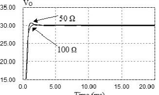
5. 1. Simulations Results Figure 4 shows the transient behaviour of the output voltage of the POESLL converter for E=9V and R=50, 100 Ω. Figure 5 shows the transient behaviour of the output voltage of the POESLL converter for E=12V and R=50, 100 Ω. From Figures 4 and 5, it can be seen that the voltage of the converter under the proposed controller has a quick settling time and small overshoot.
Figure 6 depicts the behavior of the output voltage of the POESLL converter for E=9 V and load change between 50 and 100 Ω. It is clear that the voltage of the POESLL converter under the proposed controller has a
small overshoot and quick settling time. Figure 7 shows the response of the output voltage of the POESLL converter for E=12 V and load change between 100 Ω and 50 Ω. It can be seen that the output voltage of the POESLL converter under the proposed controller has asmall overshoot and quick settling time.
TABLE 1. Parameters of the converter
Name Symbol Value
Output voltage VO 30V
Reference voltage Vd 3V
Input voltage E 9, 12V
Inductor L 0.0004H
Capacitor C1, C2 0.0001F
Output resistance R 50Ω to 100Ω
Frequency switching F 20kHz
Equivalent series resistor of inductor ESRL 0.35Ω
Equivalent series resistor of capacitor ESRC .02Ω
TABLE 2. Elements of the converter
Name Type
Switch IRFZ470
Diode 1N555
Capacitor 0.0001F/100V(electrolytic)
Inductor 4×0.0001H/5A
Op Amp LF351
5. 2. Experimental Results Figure 8 shows the experimental response of the voltage for E=9 V and load change between 50 Ω and 100 Ω. Figure 9 shows the experimental behaviour of the voltage for E=12 V and load change between 50 Ω and 100 Ω. It is clear that the closed loop system is stable in different operating conditions.
Figures 8 and 9 demonstrate the effectiveness of the POESLL converter under the proposed controller. Figures 10.a and b show the output voltage, switching signal and inductor current of the POESLL converter in steady state region for E=9V and R=50Ω and VO=30 V. Figures 11.a and b show the output voltage and switching signal and inductor current of the POESLL converter in steady state region for E=12V and R=100Ω and VO=30 V.
Figure 3. Laboratory model of the POESLL converter under the constant frequency SMC
Figure 13 depicts the response of the voltage of the POESLL converter for E=12 V and R=100 Ω and voltage change between 30 V and 42 V.
Figure 14 shows the laboratory model of the proposed system in analogue platform.
In summary, from Figures 10 and 11, it is found that the switching frequency is 20 kHz and the POESLL works in continuous conduction mode. Moreover, the simulation results of the POESLL converter under the proposed controller match the experimental results with a maximum tolerance of 1%.
Figure 4. Transient behaviour of the output voltage for E=9 V
Figure 5. Transient behaviour of the output voltage for E=12V
Figure 6. Output voltage of the POESLL converter for E=9 V and load variations between 50 and 100 Ω
Figure 7. Output voltage of the POESLL converter for E=12 V and load variations between 100 and 50 Ω
Figure 9. Experimental result for load variation and E=12V [Ch1:5V/Div-output voltage, Ch2:200mV/Div-load]
(a)
(b)
Figure 10. Experimental response of the output voltage of the POESLL converter for E=9 V and R=50 Ω in steady state region; (a) Response of the output voltage [Ch1:5 V/Div-output voltage] (b) Response of the switching signal and inductor current [Ch1:1 V/Div-inductor current and Ch2:5 V/Div-switching signal]
(a)
(b)
Figure 11. Experimental response of the output voltage of the POESLL converter for E=12V and R=100 Ω in steady state region (a) Response of the output voltage [Ch1:5 V/Div-output voltage] (b) Response of the switching signal and inductor current [Ch1:1 V/Div-inductor current and Ch2:5 V/Div-switching signal]
Figure 12. Experimental result for E=9 V and R=50 Ω and output voltage change between 30 V and 42 V[Ch1:5V/Div-output voltage and Ch2:1V/Div-load]
Figure 14. Laboratory model of a POESLL converter using a constant frequency SMC
6. CONCLUSIONS
In this paper, the design of a constant frequency SMC for output voltage regulation of the POESLL has been successfully presented. The constant frequency sliding mode control scheme has been implemented. The proposed controller ensures robustness and stability against load and input voltage variations compared with linear controllers. Simulation and experimental results are presented to show the performance of the proposed controller. The proposed controller is suitable for most commercial applications. The advantages of the proposed controller implemented in this paper are: constant frequency, simple implementation, robustness performance against load and voltage variations and less number of sensors.
7. REFERENCES
1. Hegazy, O., Van Mierlo, J. and Lataire, P., "Analysis, modeling, and implementation of a multidevice interleaved dc/dc converter for fuel cell hybrid electric vehicles", Power Electronics, IEEE Transactions on, Vol. 27, No. 11, (2012), 4445-4458.
2. Silva-Ortigoza, R., Hernández-Guzmán, V.M., Antonio-Cruz, M. and Munoz-Carrillo, D., "Dc/dc buck power converter as a smooth starter for a dc motor based on a hierarchical control", Power Electronics, IEEE Transactions on, Vol. 30, No. 2, (2015), 1076-1084.
3. Luo, F.L. and Ye, H., "Positive output super-lift converters", Power Electronics, IEEE Transactions on, Vol. 18, No. 1, (2003), 105-113.
4. Biolkova, V., Kolka, Z. and Biolek, D., "State-space averaging (ssa) revisited: On the accuracy of ssa-based line-to-output frequency responses of switched dc-dc converters", WSEAS Transactions Circuits System Vol. 2, (2010), 81-90.
5. Merdassi, A., Gerbaud, L. and Bacha, S., "Automatic generation of average models for power electronics systems in vhdl-ams and modelica modelling languages", Journal of Modelling and Simulation of Systems, Vol. 1, No. 3, (2010), 176-186. 6. Mattavelli, P., Rossetto, L. and Spiazzi, G., "Small-signal
analysis of dc-dc converters with sliding mode control", Power Electronics, IEEE Transactions on, Vol. 12, No. 1, (1997), 96-102.
7. ME, R.S.R.B., ME, S.D. and ME, S.J., "A closed loop control of quadratic boost converter using pid controller", International Journal of Engineering-Transactions B: Applications, Vol. 27, No. 11, (2014), 1653-1662.
8. Rad, M.J. and Taheri, A., "Digital controller designbased on time domain for dc-dc buck converter", International Journal of Engineering-Transactions B: Applications, Vol. 28, No. 5, (2015), 693-700.
9. Maksimovic, D. and Zane, R., "Small-signal discrete-time modeling of digitally controlled pwm converters", Power Electronics, IEEE Transactions on, Vol. 22, No. 6, (2007), 2552-2556.
10. Sarvi, M., Derakhshan, M. and Sedighizadeh, M., "A new intelligent controller for parallel dc/dc converters", International Journal of Engineering-Transactions A: Basics, Vol. 27, No. 1, (2013), 131-142.
11. Alfi, A., Hajizadeh, A. and Gholizade, N.H., "Optimal state feedback control design and stability analysis of boost dc-dc converters in fuel cell power systems using pso", International Journal of Engineering-Transactions A: Basics, Vol. 27, No. 1, (2013): 131-141
12. Salimi, M., Soltani, J., Markadeh, G.A. and Abjadi, N.R., "Indirect output voltage regulation of dc-dc buck/boost converter operating in continuous and discontinuous conduction modes using adaptive backstepping approach", Power Electronics, IET, Vol. 6, No. 4, (2013), 732-741.
13. Utkin, V., Guldner, J. and Shi, J., "Sliding mode control in electro-mechanical systems, CRC press, Vol. 34, (2009). 14. Umamaheswari, M.G., Uma, G. and Vijayalakshmi, K., "Design
and implementation of reduced-order sliding mode controller for higher-order power factor correction converters", Power Electronics, IET, Vol. 4, No. 9, (2011), 984-992.
15. Kumar, K.R. and Jeevananthan, S., "Design and implementation of reduced-order sliding mode controller plus proportional double integral controller for negative output elementary super-lift luo-converter", Power Electronics, IET, Vol. 6, No. 5, (2013), 974-989.
16. Chen, Z., Hu, J. and Gao, W., "Closed-loop analysis and control of a non-inverting buck–boost converter", International Journal of Control, Vol. 83, No. 11, (2010), 2294-2307. 17. Chen, Z., Gao, W., Hu, J. and Ye, X., "Closed-loop analysis and
18. Chen, Z., "Pi and sliding mode control of a cuk converter", Power Electronics, IEEE Transactions on, Vol. 27, No. 8, (2012), 3695-3703.
19. Kumar, K.R. and Jeevananthan, S., "Hysteresis modulation based sliding mode control for positive output elementary super lift luo converter", International Journal of Electrical and Electronics Engineering, Vol. 2, No. 3, (2009), 131-138. 20. Kumar, K.R. and Jeevananthan, S., "Sliding mode control for
current distribution control in paralleled positive output elementary super lift luo converters", Journal of Power Electronics, Vol. 11, No. 5, (2011), 639-654.
21. Fateh, M.M., Alfi, A., Moradi, M. and Modarres, H., "Sliding mode control of lorenz chaotic system on a moving fuzzy surface", in EUROCON'09. IEEE, (2009), 964-970.
22. Tan, S.-C., Lai, Y.-M., Tse, C.K., Martínez-Salamero, L. and Wu, C.-K., "A fast-response sliding-mode controller for
boost-type converters with a wide range of operating conditions", Industrial Electronics, IEEE Transactions on, Vol. 54, No. 6, (2007), 3276-3286.
23. Tan, S.-C., Lai, Y.-M. and Tse, C.K., "General design issues of sliding-mode controllers in dc–dc converters", Industrial Electronics, IEEE Transactions on, Vol. 55, No. 3, (2008), 1160-1174.
24. He, Y., Xu, W. and Cheng, Y., "A novel scheme for sliding-mode control of dc-dc converters with a constant frequency based on the averaging model", Journal of Power Electronics, Vol. 10, No. 1, (2010), 1-8.
25. Dupont, F.H., Rech, C., Gules, R. and Pinheiro, J.R., "Reduced-order model and control approach for the boost converter with a voltage multiplier cell", Power Electronics, IEEE Transactions on, Vol. 28, No. 7, (2013), 3395-3404.
Design and Implementation of a Constant Frequency Sliding Mode Controller for a
Luo Converter
A. Goudarzian, H. Nasiri, N. Abjadi
Faculty of Engineering, Shahrekord Univercity, Shahrekord, Iran
P A P E R I N F O
Paper history:
Received 19 May 2015
Received in revised form 08 September 2015 Accepted 26 January 2016
Keywords: POESLL Converter
Constant Frequency Sliding Mode Controller Laboratory Prototype ديكچ ه نيا رد ،هلاقم ي رتنک ک ﻝ هدننک ی ظنت یارب مواقم ي
ﻝدبم ژاتلو م
POESLL
اده تلاح رد ي
پ ت ي ﻝدبم .تسا هدش یفرعم هتسو
POESLL
ي ﻝدبم ک
DC/DC
هرهب اب ی ا زا .تسلااب ژاتلو ﻝاقتنا ي
ﻝدبم ن یم س ،تباث ناوت عبانم رد ناوت ي
متس اه ی
و یتارباخم ب .درک هدافتسا یتعنص یاهدربراک ه
لک درکلمع رطاخ ي
ﻝدبم راتخاس ،ینزد
POESLL
غ ي هولاع .تسا یطخر
ا رب ي ا راتخاس ،یدورو ژاتلو و راب تاناسون رطاخ هب ،ن ي
غتم ﻝدبم ن ي ظنت و درکلمع دوبهب روظنم هب .تسا نامز اب ر ي
ژاتلو م
ن ﻝدبم ،یجورخ ي
هب زا ي رتنک ک ﻝ هدننک ی رتنک .دراد مواقم ﻝ
هدننک ی پ ي ا رد هدشداهنش ي
دم ﻝرتنک شور ساسا رب هلاقم ن
یحارط تباث سناکرف یشزغل یم
رتنک .دوش ﻝ دننک ه غ راتخاس اب بسانتم یشزغل دم یاه ي
غتم و یطخر ي
دبم نامز اب ر ﻝ
یاه
DC/DC
رتنک درکلمع .دنتسه ﻝ
هدننک ی پ ي ا رد هدشداهنش ي
مرن رد هلاقم ن ا
رازف
PSIM
ا رب هولاع .تسا هدش یسررب ي
ن ،
ي ا رد .تسا هدش هتخاس نآ زا هنومن ک ي
بش ،یحارط ،هلاقم ن ي
ه اس اتن و یز ي هئارا یلمع ج یم
رثؤم درکلمع ات دنوش
رتنک ﻝ پ هدننک ي ظنت یارب یداهنش ي
ﻝدبم یجورخ ژاتلو م
POESLL
.دنهد ناشن ار
![Figure 12. Experimental result for E=9 V and R=50 Ω and output voltage change between 30 V and 42 V[Ch1:5V/Div-output voltage and Ch2:1V/Div-load]](https://thumb-us.123doks.com/thumbv2/123dok_us/220320.2016538/7.595.81.261.255.532/figure-experimental-result-output-voltage-change-output-voltage.webp)