Special Issue on Recent Advances in Engineering Systems
Low Probability of Interception Beampattern Using Frequency
Diverse Array Antenna
Shaddrack Yaw Nusenu*
1Koforidua Technical University, Electrical / Electronic Department, Faculty of Engineering, Ghana.
A R T I C L E I N F O A B S T R A C T
Articlehistory:
Received:12 February,2017 Accepted:31March,2017 Online:02 April,2017
Frequency diverse array (FDA) antenna employs a small frequency increment, as compared with the carrier frequency, across antenna array elements.Theuseofafrequencyincrementgeneratesanarrayfactorthatis dependent onangle, time, and the rangeand thisyields a rangeand angle dependent beampattern. In this paper, a transmit array beamformingFDA employing costasequencefrequency incrementsisproposedthat offers low probabilityofinterception(LPI)forradarsystems.Becauseactiveradarsare highlyvisibletointerceptreceivers,FDAbeamwithuniformlineararrayand non-linearly increasing frequency offsets to reduce the system visibility is replaced by the conventional high gain phased-array antenna beam. The proposed method produce random-like peak distribution without obvious peaks making it difficultto be detected by unfriendly detector or intercept receiverswithout knownofthe specified codingsequence for the frequency increments.Numericalsimulationresultsverifytheproposedmethod. Keywords:
Frequencydiversearray costasequence
Lowprobabilityofintercept Transmitbeamforming
1
Introduction
Phased-array antenna has been extensively employed in many applications such as radar, electronic warfare, radio astronomy and airport safety etc. This is because it can steer the high-gain beam electronically with high effectiveness towards any desired direction [1, 2, 3]. The directional gain obtainable by employing phased-array antenna is beneficial for detecting, tracking weak targets and suppressing side-lobe interferences from other directions [4]. Conversely, the high gain beam is visible to intercept receivers which will degrade the capability of the surveillance system [5]. Furthermore, active surveillance radars are highly suscepti-ble to detection and interception by opposing forces. The electronic support measures (ESM) can be used to intercept the radar transmission and possibly facilitate harmful elec-tronic counter-measures (ECM) techniques [6]. Therefore it is essential to develop low probability of intercept (LPI) radar systems.
LPI radar system employs a distinct emitted waveform intended to prevent a non-cooperative intercept receiver from intercepting and detecting its emission. On the other hand, low probability of identification (LPID) radar sys-tem uses a special radiated waveform intended to prevent a non-cooperative intercept receiver from intercepting and detecting its emission but if intercepted, identification of the
radiated waveform modulation and its parameters becomes difficult. It is worth mentioning that LPID radar is an LPI radar [7].
Several techniques have been introduced to reduce radar visibility and improve its LPI ability [8]. Mostly, three main areas are considered in order to reduce radar visibil-ity [6]: (i) spreading the energy in time with high duty cy-cle waveforms (ii) spreading the energy in frequency with wide bandwidth waveforms (iii) spreading the energy in space through broad transmitter antenna beams. In [9], fre-quency hopping, orthogonal frefre-quency division multiplex-ing (OFDM), and random waveforms have been put for-ward for LPI radars. In [10], switched antenna technique called antenna hopping method which uses irregular scan patterns to reduce the susceptibility to receivers was intro-duced to enhance the LPI performance. Although with spe-cific beamforming technique, the probability of being de-tected in sidelobe region can be reduced. In [6], LPI trans-mit array beamforming method was proposed which em-ployed phased array antenna. Even though phased-array antenna has been widely employed for numerous applica-tions, it produce fixed steering beam at an angle for all the ranges [11].
A new flexible antenna array called frequency diverse array (FDA) has been introduced in [12, 13]. The authors reported that the range-angle-time dependent ffield
ar-*Shaddrack Yaw Nusenu, Koforidua Technical University, Ghana, Email: [email protected]
FDA was defined in [15] as an antenna aperture where the frequency of each antenna element is controlled indepen-dently to steer the main beam, depending on the time do-main of each frequency component in the far-field. The most significant feature of FDA, as opposed to phased-array, is that the former employs a small frequency incre-ment across its antenna array eleincre-ments. This frequency in-crement makes the array beampattern to change as a func-tion of the range, angle and time [11, 12, 13]. In [14], FDA radar using costas sequence modulated frequency in-crements was proposed to decoupled the range and angle beampattern, in which only FDA applications are consid-ered.
In this paper, LPI FDA transmit beamforming with costa sequence frequency increments is proposed. The pro-posed method transmitted beampattern will have a random-like peak distribution without obvious peaks. This implies that it will be difficult for the intercept receiver from inter-cepting and detecting without known of the specified coding sequence for the frequency increments.
The rest of the paper is organized as follows: Section 2 proposes the LPI beamforming using costas sequence FDA antenna, which is verified in Section 3 with numerical re-sults. Finally Section 4 concludes the paper.
2
LPI FDA BEAMFORMING
Consider an FDA withMelements which can be excited by either the same waveform or different waveforms. In this paper, we assume costas sequence frequency increments used for themth element is∆fm as shown in Figure 1. In the costas coding technique frequencies for the subpulses are chosen in a random pattern, according to some prede-termined rule. Consider the frequency-time matrix shown in Figure 2(a), (b) and (c). In this case, the rows are in-dexed fromi= 1,2, ..., Mand the columns are indexed from j = 0,1,2, ...,(M−1). The rows and columns are used to denote subpulses and distinct frequencies, respectively. As shown in Figure 2(a), (b) and (c) a dot indicates the distinct frequency value assigned to the associated subpulse. In this fashion, the frequency assignments are chosen randomly. The element of the difference matrix in rowiand columnj is given as
Di,j=ai+j−aj, i+j≤M (1)
whereaiis theith element of the coding sequence. The remaining locations (wherei+j > M) are left blank. Us-ing (1) the first row is formed by takUs-ing differences between adjacent elements in the coding sequence, then second row by taking differences between next-adjacent elements, and so forth. We employ this technique for FDA antenna, thus, only one carrier frequency is transmitted by any one of the M FDA elements and each carrier frequency is permitted only once. In [16], the details for the construction algo-rithms for costas signals can be found.
The radiated frequency fed to themth of the LPI FDA using costas frequency increments can be given as
fm=f0+∆fm, m= 0,1,2, . . . , M−1 (2)
quency increment, respectively, andMis the number of ar-ray elements. Specifically, standard FDA is achieved when
∆fm = m∆f. Suppose a far-field position with range and angle (r,θ), the phase of the transmitted signal ofmth ele-ment is represented by
αm(r, θ) = (f0+∆fm)rmβ (3)
rm=r+mdsinθ, m= 0,1,2, . . . , M−1 (4)
wheredis the element spacing. Hence, the phase dif-ference between the signals transmitted by themth and first elements can be approximately given as
ψm(r, θ) =−βf0mdsinθ+∆fmrβ−βm∆fmdsinθ (5)
Next, we apply a set of costas frequency coding, ∆fm and phases,δm(r)to each element to achieve a “spoiled’ low-gain beamforming. Hence the transmit array factor (AF), which can be seen as the fundamental basis pattern [17, 18] is expressed as
AF0(r, θ) =
M−1 X
m=0
e−jβf0mdsinθ·ej∆fmβr·e−jβ∆fmmdsinθ·e−jδm(r)
(6) where∆fmis designed using Welch-constructed costas coding sequence andδm(r)can be designed using optimiza-tion algorithms. By applying a linear phase progression to (6) in increments ofκ=2Nπ for first pattern,2κfor the sec-ond pattern and so forth, additional patterns can be created. In such a fashion,(N−1)patterns can be generated. There-fore (6) can be formulated as (7) [18] at the top of the next page, wheren= 1,2, ..., N.
It is worth mentioning that, theseN steered versions of the fundamental guarantee linear independence. Moreover, they all exhibit low gain and broad beamwidth. Therefore their peak power can be significantly reduced in any direc-tions to ensure LPI property.
Furthermore, to retain the array radar performance and simultaneously achieving LPI property, we synthesize the high gain patterns along the desired direction by linear com-binations of the basis patterns. Suppose thenth basis pattern is weighted by the complex coefficientw0,n, thenN trans-mit beampatterns can be expressed in matrix formulation as given in (8), [6, 18].
This implies that using (8), high gain beampatterns can be formed by linearly combinations of theN basis patterns.
3
NUMERICAL RESULTS
In the simulations, we assume the LPI FDA operating at a carrier frequency off0= 10GHz. An 32 elements uniform
linear array is used for the standard FDA and phased-array beamforming (see Figure 4). The transmit array element spacing is designed to bed= c0
d
0
f
0f
f
0f
00 0
f
f
f
0f
10 2
f
f
f
0f
M 10
f
f
12
f
f
M 11
( )
r
0
( )
r
2( )
r
M 1( )
r
0 0 d 0
f
0f
f
0f
00 0
f
f
00f
0f
111110 2
f
f
22f
0f
ff
MMMMMMM 1110
f
0000f
111112
f
2222f
f
f
f
f
f
f
MMMMM 111 1( )
r
1 1 1 1 1
( )
( )
))
0( )
r
0 0 0 0
0
( )
( )
)
222222( )
r
))))
MM 11( )
( ))
( ))))
r)
Figure 1: Illustration of LPI FDA.δmand∆fmdenotes phase shifters and costas coding frequency increments for themth element, repectively.
AFN−1(r, θ) =
M−1 X
m=0
e−(N−1)mκe−jβf0mdsinθ·e−j∆fmβr·e−jβ∆fmmdsinθ·e−jδm(r) (7)
A0(r, θ)
.. . AN−1(r, θ)
=
w0,0 · · · w0,N−1
..
. . .. ...
wN−1,0 · · · wN−1,N−1
AF0(r, θ)
.. . AFN−1(r, θ)
(8) Time Frequency (a) Time Frequency (b) Time Frequency (c)
(a) (b)
(c)
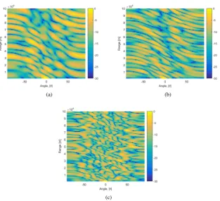
Figure 3: Illustration of LPI FDA beampattern using costas sequence coding: (a)M= 10, (b)M= 12, (c)M= 15.
(a) (b)
(a) (b)
(c)
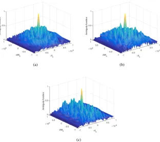
Figure 5: Illustration of three-dimensional ambiguity function LPI FDA using costas sequence coding: (a)M= 10, (b)M = 12, (c)M= 15.
their frequency-time matrix representation is shown in Fig-ure 2.
Next, we show the LPI FDA transmit beamforming em-ploying costas sequence withM = 10, M = 12, M = 15, respectively, in Figure 3. It can be seen that for the re-spective costas sequence coding employed, the LPI FDA transmit beamforming has random-like peak distributions without noticeable peaks. This characteristics implies that it is very difficult to be intercepted and detected by intercept receivers or unfriendly detectors without the knowledge of the specified costas coding sequence used for the frequency increments.
Suppose∆f = 5kHz, Figure 4(a) shows the standard FDA when specifically∆fm= m∆f. It can be observed that it produces range and angle dependent and range-angle cou-pling transmit beamforming. This feature can be exploited for range and angle localization of radar targets. Differ-ently, the phased-array produce angle-dependent only trans-mit beamforming, as shown in Figure 4(b). However, the phased-array provides no range information because of its range-independent beamforming.
Finally, the ambiguity function of LPI FDA costas cod-ing sequence is shown in Figure 5 for distinctM. It can be seen that the ambiguity functions accumulates into a spike, thus clearly resembles thumb-tack response.
4
CONCLUSION
This paper proposed a transmit beamforming technique us-ing FDA which offers LPI for surveillance systems. The high-gain phased-array antenna beam is replaced with the
low gain FDA beams with nonlinear frequency increments to reduce the system visibility. The proposed technique achieves the same performance as the traditional high-gain beam. The obvious advantage of the proposed technique presented here is the random-like peak energy distributions without noticeable peaks. The results show that the pro-posed technique has the advantages of both FDA radar and guarantee LPI property. The frequency increments are cho-sen from Welch constructed costas coding sequence across the array element to ensure the LPI property for radar sys-tems. Overall, the proposed technique can possibly be com-bined with other LPI waveform design techniques to further reduce the susceptibility and visibility of LPI radar systems.
Conflict of Interest The author declare no conflict of in-terest.
Acknowledgment The author would like to thank Re-spected Professor Wen-Qin Wang (Senior Member - IEEE) of UESTC for his great contributions, support and encour-agement.
References
[1] T. A. Lam, D. C. Vier, J. A. Nieslsen, C. G. Paraz-zoli, and M. H. Tanielian. “Steering phased array an-tenna beams to the horizon using a buckyball NIM lens,”Proc. IEEE, vol. 99, no. 10, pp. 1755-1767, Oct. 2011.
pat-Propag. Mag., vol. 54, no. 3, pp. 184-193, Jun. 2012.
[3] C. J. Reddy. “Phased array-based systems and appli-cations,”IEEE Antennas Propag. Mag., vol. 39, no. 5, pp. 102-103, Oct. 1997.
[4] Li, J., Stoica, P. “The phased array is the maximum SNR active array,”IEEE Signal Process. Mag., 27, (2), pp. 143-144, 2010.
[5] O. G. Vendik and D. S. Kozlov. “Phased antenna array with a sidelobe cancellation for suppression of jam-ming,”IEEE Antennas and Wireless Propagation Let-ters, vol. 11, 2012.
[6] D. E. Lawrence. “Low probability of intercept an-tenna array beamforming,”IEEE Transactions on An-tennas and Propagation, vol. 58, no. 9, pp. 2858-2865, September 2010.
[7] Phillip E. Pace. “Detecting and Classifying Low Prob-ability of Intercept Radar,”Second Edition 2009.
[8] V. Krisnamurthy. “Emission management for low probability intercept sensors in network centric war-fare,”IEEE Transactions on Aerospace and Electronic Systems, vol. 41, no. 1, pp. 133-151, January 2005.
[9] W.-Q. Wang. “MIMO SAR OFDM chirp wave-form diversity design with random matrix modula-tion,”IEEE Transactions on Geoscience and Remote Sensing, vol. 53, no. 3, pp. 1615-1625, March 2015.
[10] E. J. Baghdady. “Directional signal modulation by means of switched spaced antennas,”IEEE Transac-tions on CommunicaTransac-tions, vol. 38, no. 4, pp. 399-403, April 1990.
opportunites,”IEEE Antennas and Propagation Maga-zine, vol. 57, no. 2, pp. 145-152, April 2015.
[12] P. Antonik, M. C. Wicks, H. D. Griffiths, and C. J. Baker. “Range dependent beamforming using element level waveform diversity,” in Proceedings of the Inter-national Waveform Diversity and Design Conference, Las Vegas, USA, pp. 1-4, January 2006.
[13] P. Antonik, M. C. Wicks, H. D. Griffiths, and C. J. Baker. “Frequency diverse array radars,” in Proceed-ings of the IEEE Radar Conference, Verona, NY, April pp. 215-217, 2006.
[14] Shaddrack Yaw Nusenu, Zhe Wang, Wen-Qin Wang. “FDA radar using Costas sequence modulated fre-quency increments,” in Proceedings of CIE Interna-tional Radar Conference, pp. 1058–1061. 2016.
[15] Wen-Qin Wang, H. C. So, and Alfonso Farina. “An Overview on Time/Frequency Modulated Array Pro-cessing ,” DOI 10.1109/JSTSP.2016.2627182, IEEE Journal of Selected Topics in Signal Processing.
[16] S. W. Golomb and H. Taylor. “Constructions and prop-erties of costas arrays,”Proceedings of the IEEE, vol. 72, no. 9, pp. 1143-1163, September 1984.
[17] Wen-Qin Wang. “Adaptive Rf Stealth Beamforming For Frequency Diverse Array Radar,”23rd European Signal Processing Conference (EUSIPCO) pp. 1158-1161, 2015.