AN EXPERIMENTAL STUDY OF THE EFFECT OF PRESSURE INLET
GAS ON A COUNTER-FLOW VORTEX TUBE
Mahyar Kargaran,
*Mahmood Farzaneh-Gord
Faculty of Mechanical Engineering, Shahrood University of Technology, Shahrood, Iran
A
BSTRACTVortex tube is a simple device which separate an inlet gas with a proper pressure into hot and cold flows .This device is well-suited for generating cooling load gas because it provides the cold gas without using any refrigerants . Many research works has been carried out in order to identify the factors which contribute to Vortex tube performance. Here, an experimental study has been made to determine the effect of geometrical (length of vortex tube) and thermo-physical (pressure) parameters on vortex tube performance and air also used as a working fluid.
Keywords: Vortex tube ,geometrical parameters ,thermo-physical parameter .
* Corresponding Author. E-mail: [email protected]
1.
INTRODUCTION
Vortex tube is a simple device which separate an inlet gas with a proper pressure into hot and cold flows. This device is well-suited for generating cooling load gas because it provides the cold gas without using any refrigerants. Many research works has been carried out in order to identify the factors which contribute to Vortex tube performance. Here, an experimental study has been made to determine the effect of geometrical (length of vortex tube) and thermo-physical (pressure) parameters on vortex tube performance and air also used as a working fluid.
The vortex tube is a device without a moving part with the ability of separating hot and cold air from a higher pressure inlet gas which is tangentially blown into vortex chamber. Such a separation of the flow into regions of low and high total temperature is referred to as the temperature (or energy) separation effect. It contains the following parts: one or more inlet nozzles, a vortex chamber, a cold-end orifice, a hot-end control valve and a tube. When high-pressure gas is tangentially injected into the vortex chamber via the inlet nozzles, a swirling flow is created inside the vortex chamber. When the gas swirls to the center of the chamber, it is expanded and cooled. In the vortex chamber, part of the gas swirls to the hot end, and another part exists via the cold exhaust directly. Part of the gas in the vortex tube reverses for axial component of the velocity and move from the hot end to the cold end. At the hot exhaust, the gas escapes with a higher temperature, while at the cold exhaust, the gas has a lower temperature compared to the inlet temperature. The vortex tube was first discovered by Ranque, a metallurgist and physicist who was granted a French patent for the device in 1932, and a United States patent in 1934. The initial reaction of the scientific and engineering communities to his invention was disbelief and apathy. Since the vortex tube was thermodynamically highly inefficient, it was abandoned for several years. Interest in the device was revived by Hilsch, a German engineer, who reported an account of his own comprehensive experimental and theoretical studies aimed at improving the efficiency of the vortex tube.
Separating cold and hot flows by using the principles of the vortex tube can be applied to industrial applications such as cooling equipment
in CNC machines, refrigerators, cooling suits, heating processes, etc. The vortex tube is well-suited for these applications because it is simple, compact, light, quiet, and does not use Freon or other refrigerants (CFCs/HCFCs). It has no moving parts and does not break or wear and therefore requires little maintenance. But, its low thermal efficiency is a main limiting factor for its application. Also the noise and availability of compressed gas may limit its application. In this research numerical and experimental method will be implemented to determine the significant factors on vortex tube behavior with an incompressible flow in order to boost vortex tube energy (thermal) efficiency.
Nimbalkar and Muller (2009) presented the results of a series of experiments focusing on various geometries of the ‘‘cold end side” for different inlet pressures and cold fractions. The experimental results indicated that there is an optimum diameter of cold-end orifice for achieving maximum energy separation. It was observed that for cold fraction less or equal than 60%, the effect of cold end orifice diameter is negligible and above 60% cold fraction it becomes prominent. The results also show that the maximum value of performance factor was always reachable at a 60% cold fraction irrespective of the orifice diameter and the inlet pressure.
Dincer et al. (2009) have studied the effects of position, diameter and angle of a mobile plug, located at the hot outlet side experimentally to get the best performance. The most efficient (maximum temperature difference ) combination of parameters is obtained for a plug diameter of 5 mm, and tip angle of 30 or 0 600, by keeping the plug in the same
position, and letting the air enter into the vortex tube through 4 nozzles. Increasing the inlet pressure beyond 380 kPa did not cause any appreciable improvement in the performance. Stephan et al. (1983) measured the temperature profiles at different positions along a vortex tube axis and concluded that the length of the vortex tube would have an important influence on the transport mechanism inside.
Saidi and Valipour (2003) presented information data on the classification of the parameters affecting vortex tube operation. In their study, the thermophysical parameters such as inlet gas pressure, type of gas and cold gas mass ratio, moisture of inlet gas, and the geometrical parameters, i.e., diameter and length of main tube diameter of the outlet orifice and shape of the entrance nozzle, were designated and studied.
Frontiers in Heat and Mass Transfer
Orhan and Muzaffer (2006) have carried out a series of experiments to investigate the effects of the length of the pipe, the diameter of the inlet nozzle, and the angle of the control valve on the performance of the counterflow vortex tubes for different inlet pressures. Experiments showed that the higher the inlet pressure, the greater the temperature difference of the outlet streams. It was also shown that the cold fraction is an important parameter influencing the performance of the energy separation in the vortex tube. Optimum values for the angle of the control valve, the length of the pipe and the diameter of the inlet nozzle were obtained.
There have been other media than air used as the working fluid. Balmer (1988) applied liquid water as the working medium. It was found that when the inlet pressure is high, for instance 20~50 bar, the energy separation effect still exists. So it proves that the energy separation process exists in an incompressible vortex flow as well. Eiamsa-ard and Promvonge (2008) presented a complete overview of the past investigations of the mean flow and temperature behaviours in a turbulent vortex tube in order to understand the nature of the temperature separation or Ranque–Hilsch effect. They have proposed optimum values for the cold orifice to the VT inlet diameter (d/D) of 0.5, the angle of the conical control valve of 50 degrees, the length of the vortex tube to the VT inlet diameter (L/D) of 20 and the diameter of the inlet nozzle to the VT inlet diameters (δ/D) of 0.33 for air as the working fluid.
Providing cooling load has always been one of the major challenges and one the other hand ,using refrigerants such as Freon (which causes global warming) has been increasing .This device is well-suited for generating cooling load gas because not only it is light ,simple and compact but also provides the cold gas without using any refrigerants In this research an experimental investigation has been carried out to investigate The effects of the VT tube length and the pressure of inlet air on the VT thermal separation. Further, the amount of cooling capacity created as air pass through a VT has been calculated and compared when air with 4.2 and 5.8 bar were injected into vortex tube. As discussed above, it will have potential applications in refrigerators.
2.
THE VORTEX TUBE PARAMETERS
There are a few important parameters affecting the VT thermal behavior which should firstly be introduced
2.1
The geometrical parameters
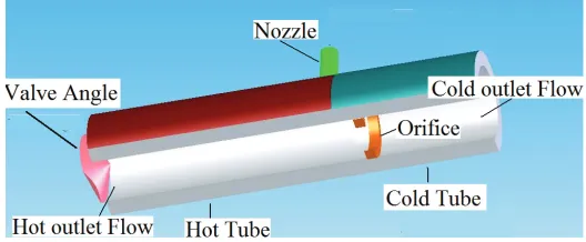
Figure 1 shows a schematic diagram of a counter flow vortex tube which was constructed and used in this study. As shown in Fig.3, the geometrical parameters are inlet VT diameters (D), cold orifice diameter (d), inlet nozzle diameter (δ), conical controlling valve angle (Ф), cold tube length (
L
c) and hot tube length (L
h) and N is the number of nozzle . Table 1 shows the detailed geometrical parameters dimensions used in this study. These values are selected based on proposed optimum values by Eiamsa-ard and Promvonge (2008). As can be seen, the cold orifice diameter was 17.1 mm and hot tube length was varied from 250 to 769 mm.Table 1 The geometrical parameters and their values
Parameters value
D 25mm
d 17.1mm
Ф 50 degree
δ 8mm
Lc 50 mm
N 1
Lh 250 mm 519 mm 769mm
Fig. 1 The schematic diagram of a counter flow vortex tube
2.2
The flow parameters
As mentioned by Eiamsa-ard and Promvonge (2008), the most important flow parameter is believed to be cold mass fraction ,defined as: i c c
m
m
=
μ
(1)where
m
candm
iare the mass flow rates at the inlet of the vortex tube and at the cold outlet, respectively. The other flow parameters are:a) The cooling (
Δ
T
c) and the heating (Δ
T
h) effects of the vortex tube are defined as follows , respectively:c i c
T
T
T
=
−
Δ
(2)i h h
T
T
T
=
−
Δ
(3)where
T
i is the inlet stream temperature,T
c is the outlet stream temperature of the cold end andT
h is the outlet stream temperature of the hot end.b) The performance of the vortex tube was defined as the difference between the heating effect and the cooling effect. Subtracting Eq. 2 from Eq. 3 gives the vortex tube performance equation as follows (Eq. 4):
c h
T
T
T
=
−
Δ
(4)c) the cooling capacity which is defined as:
)
(
i c c c cC
m
h
m
h
h
Q
=
Δ
=
−
(5)For the case of an ideal gas, the cooling capacity may be defined as:
c p c c i p c c c
C
m
h
m
c
T
T
m
c
T
Q
=
Δ
=
(
−
)
=
Δ
(6)Considering above definitions, the specific cooling capacity can be derived as follow:
c c i c
c
m
h
Q
q
=
=
μ
Δ
(7)3.
EXPERIMENTAL APPARATUS
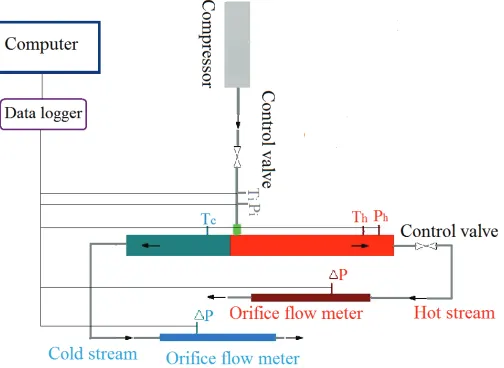
to control the flow rate of the hot stream. This would help to regulate cold mass friction. Two orifice flow meters constructed according to ISO5167 are employed to measure the mass flow rate of the hot and cold streams. 3 PT100 temperature sensors are installed to measure inlet, hot and cold stream temperatures. 2 pressure transmitters are utilized to quantify inlet pressure and outlet pressure of hot streams.
Fig. 2 A schematic diagram of experimental layout
Figure 3 shows the experimental test bed has been conducted at Koolab Toos Company to investigate thermal separation of air as working fluid. The inlet pressure was varied during experiments from 4.2 to 5.8 bar which are gauge pressure and the inlet temperature was 25.4 C° .Noting from the figure, the hot length of the VT and hot stream flow meter were painted in red. In other hand, the cold length of the VT and cold stream flow meters were painted in blue. The VT was made from steel with inlet diameter of 25 mm. During the tests, the hot tube length of the VT was varied among 3 available as detailed in Table 1.
Fig. 3 The experimental test bed in operation
4.
ERROR ANALYSIS
The errors associated with temperature measurements are computed in this section. The maximum possible errors in various measured parameters ;namely ,temperature and pressure ,were estimated by using the method proposed by Moffat (1985). Errors were estimated from the minimum values of output and the accuracy of the instrument. This method is based on careful specification of the uncertainties in the various experimental measurements. If an estimated quantity, Y depends ,depends on independent variables like
x
i then the error in the value of “Y” is given by
∂
=
∂
ni i
x
x
Y
Y
1 2
)
(
(8)where
i i
x
x
∂
are the errors in the independent variables.i
x
∂
= Accuracy of the measuring instrumenti
x
=Minimum Value of the output measured4.1 Error in temperature measurement
PT100 temperature sensors were used to measure the gas temperatures. Temperatures are logged in file with accuracy of 0.10c. The maximum
possible error in the case of temperature measurement was calculated from the minimum values of the temperature measured and accuracy of the instrument. The error in the temperature measurement is:
∂
T
T
=
(
∂
T
PT100T
min)
2
+
(
∂
T
logT
min)
2
=
(
.5
12
)
2
+
(
.1
12
)
2
≈
0.04
=
4%
(9)4.2 Error in pressure measurement
Pressure transmitters were used to measure the gas pressure. Pressures directly are logged in file with accuracy 0f 0.01 bar. The error in the pressure measurement is:
∂
P
P
=
(
∂
P
maxP
min)
2
+
(
∂
P
logP
min)
2
=
(
.01
1.33
)
2
+
(
.0.01
1.33
)
2
≈
0.01
=
1%
(10)4.3 Error in flow rate measurement
Flow measurement has been made using orifice flow meters. Uncertainty analysis was conducted according to the standard procedures reported in ISO5167. The analysis shows that the error in the flow rate measurement is 4.5%.
5.
RESULT AND DISCUSSION
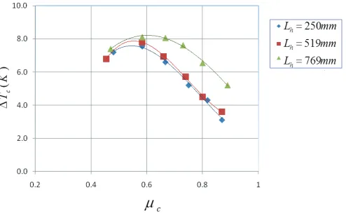
Figure 4 shows the effects of tube length on non-dimensional hot temperature differences when p=5.8 bar. As the graph shows , the tube with Lh =769 mm creates the highest cold temperature differences. It should be also noticed that there is a
μ
c in each case which causes the temperature differences to be maximized. For this case, atμ ≈
c0.59
the highest cold temperature differences are generated .
Fig. 4 Effect of Lh on cold temperature difference
Fig. 5 Effect of Lh on hot temperature difference
Fig. 6 Effect of Lh on cold temperature difference
Figure 7 indicates the effects of tube length on non-dimensional hot temperature differences when p=4.2 bar. As the graph demonstrates, the tube with Lh =250 mm produced maximum hot temperature differences and at
μ
c≈
0.75
the highest hot temperature differences are produced. Figure 8 shows the effects of hot tube length on specific cooling capacity when p=5.8 bar. As can be seen, the tube with Lh =769 mm produces the highest specific cooling capacity at0.65
cμ
≈
while the tube with Lh =250 mm creates the lowest amount of cooling capacity.Nikolaev et al. (1995) found that the maximum refrigeration capacity of the vortex tube falls within the range from 60% to 70% cold fraction. Poshernev and Khodorkov (2003) mentioned that within their
range of input parameters the refrigerating capacity has a distinct maximum at a cold fraction of about 50%–60%. Nimbalkar and Muller (2009) mentioned that the maximum value of performance factor was always reachable at a 60% cold fraction irrespective of the orifice diameter. As can be seen from figure 8, our results also show that maximum cooling capacity is encountered at about 65% cold fraction regardless of the orifice diameter. This phenomenon can be explained on the basis of pressure balance inside the vortex tube, discussed by Love (1974), and Piralishvili and Fuzeeva (2005).
Figure 9 shows the effects of hot tube length on specific cooling capacity when p=4.2 bar. The graph indicates that the tube with Lh =769 mm produces maximum specific cooling capacity (like the previous diagram) at
μ
c≈
0.58
. On the other hand, tube with Lh =250 mm has the lowestq
c in this regard.Fig. 7 Effect of Lh on hot temperature difference
Fig. 8 Effect of Lh on specific cooling capacity
6.
CONCLUSION
An experimental study has been carried out to offer optimum values for the length of VT to its inlet diameter(L /D)
h and assessed the
pressure inlet gas factor on vortex tube performance .The comparison between Figures 4-7 demonstrated that cold temperature difference lightly and hot temperature difference dramatically increases as the inlet pressure increases .In this study ,
Δ
T
c reached about 8 degree centigrade andΔ
T
h went over 20 degree centigrade for p=5.8 bar. The results also show that hot temperature difference is maximized for a specificL
h. In this regard, L /D =250 /25 =10h . As far as cooling
capacity and hot temperature difference are concerned ,the study indicates that for Lh/D=769/25=30.76 we have maximum proficiency. As for
μ
c value, at μc≈0.6 , we witness the maximum of cold temperature difference and cooling capacity , while for hot temperature differenceμ
c is about .75.ACKNOWLEDGEMENTS
This study has been supported by Semnan (Iran) Gas Company. Special thanks also go to Koolab Toos company. The authors are also grateful to the reviewers of this paper for their time and valuable comments .
NOMENCLATURE
D vortex tube inlet diameter (mm)
d cold orifice diameter (mm) L vortex tube length (mm)
Lh hot tube length (mm)
Lc cold tube length (mm)
P pressure (bar)
c
Q
cooling capacity (Kw)c
q
specificcooling capacity (kj/kg)RHVT Ranque-Hilsch vortex tube
T temperature (K)
T
Δ
temperature difference (K)VT Vortex tube
m
mass flowc
μ
cold mass fraction tubeGreek Symbols
δ inlet nozzle diameter(mm) Ф conical controlling valve angle
Superscripts
1 inlet gas condition of the pressure drop
2 outlet gas condition of the pressure drop
Subscripts
c cold stream
h hot stream
i inlet stream
REFERENCES
Balmer R.T.,1998, “Pressure-driven Ranque-Hilsch Temperature Separation in Liquids,” ASME, J. Fluids Engineering 110, 161–164.
http://dx.doi.org/10.1115%2F1.3243529
Cockerill T., 1995, “The Ranque–Hilsch Vortex Tube”, PhD thesis, Cambridge University, Engineering Department, Sunderland.
Collins R.L., Lovelace R.B. 1997, “Experimental Study of Two-phase propane expanded through the Ranque-Hilsch tube,” Trans. ASME, J. Heat Transfer 101, 300–305.
http://dx.doi.org/10.1115%2F1.3450964
Dincera K., Baskayab S., Uysalc B.Z., Ucguld I., 2009, “ Experimental Investigation of The Performance of a Ranque–Hilsch vortex tube with regard to a plug located at the hot outlet,” International journal of refrigeration 32, 87–94.
http://dx.doi.org/10.1016%2Fj.ijrefrig.2008.06.002
Eiamsa-ard S., Promvonge P. ,2008,“ Review of Ranque–Hilsch Effects in Vortex Tubes,” Renewable and Sustainable Energy Reviews 12, 1822–1842.
http://dx.doi.org/10.1016%2Fj.rser.2007.03.006
Hilsch R., 1947, “ The Use of Expansion of Gases in a Centrifugal Field as a Cooling Process,” Rev Sci Instrum. 18, 2, 108–13.
ISO-51671, Measurement of fluid flow by means of pressure differential devices inserted in circular-cross section conduits running full - Part1:
General principles and requirements. & Part 2: Orifice Plates.
Khodorkov L., Poshernev N.V., Zhidkov. M.A. (203) “The vortex Tube—a Universal Device for Heating, Cooling, Cleaning, and Drying Gases and Separating Gas Mixtures,” Chemical and Petroleum Engineering 39, 7-8, 409–415.
Kulkarni M.R., Sardesai C.R.,2002, “Enrichment of Methane Concentration Via Separation of Gases Using Vortex Tubes,” J. Energy Engrg 128, 1, 1–12.
http://dx.doi.org/10.1061%2F%28ASCE%290733-9402%282002%29128%3A1%281%29
Lin S., Chen J.R., Vatistas G.H. ,1990, “A Heat Transfer Relation for Swirl Flow in a Vortex Tube”, Can J Chem Eng 68, 6, 944–7.
http://dx.doi.org/10.1002%2Fcjce.5450680608
Lewins J., Bejan A., 1995, “Vortex Tube Optimization Theory”, Energy
24, 931–943.
http://dx.doi.org/10.1016%2FS0360-5442%2899%2900039-0
Love W.J. ,1974, “Prediction of Pressure Drops in Straight Vortex Tube,” AIAA J. 12, 7.
http://dx.doi.org/10.2514%2F3.49387
M.Farzaneh –Gord ,M.Kargaran, 2010,“Recovering Energy at Entry of Natural Gas into Customer Premises by Employing a Counter-Flow Vortex Tube ,”Oil,Gas Science and Technology-Revue de l’IFP ,Vol.65, No .6,pp.903-912
http://dx.doi.org/10.2516%2Fogst%2F2009074
Farzaneh–Gord, M., Kargaran, M., Bayat, Y., Hashemi, SH, 2012, “Investigation of Natural Gas Thermal Separation through a Vortex Tube,” Enhanced Heat Transfer,Vol.19, No .187-94.
http://dx.doi.org/10.1615%2FJEnhHeatTransf.2012001545
Moffat, R.J., 1985, “Using Uncertainty Analysis in the Planning of an Experiment”, Trans. ASME, J. Fluids Eng. 107, 173-178.
http://dx.doi.org/10.1115%2F1.3242452
Nikolaev V.V., Ovchinnikov V.P., Zhidkov M.A. ,1995, “ Experience from the Operation of a Variable Vortex Tube in a Gas Separating Station,” Gaz. Prom 10, 13.
Nimbalkar S.U., Muller M.R. ,2009, “ An Experimental Investigation of the Optimum Geometry for the Cold end Orifice of a Vortex Tube,”
Applied Thermal Engineering 29, 509–514.
http://dx.doi.org/10.1016%2Fj.applthermaleng.2008.03.032
Piralishvili S.A., Polyaev V.M. ,1996, “Flow and Thermodynamic Characteristics of Energy Separation in a Double-Circuit Vortex Tube-an Experimental Investigation,” Exp Thermal Fluid Sci 12, 4, 399–410.
http://dx.doi.org/10.1016%2F0894-1777%2895%2900122-0
Piralishvili A., Fuzeeva A.A.,2005, “Hydraulic Characteristics of Ranque–Hilsch Energy Separators,”High Temp 43, 6, 900–907.
http://dx.doi.org/10.1007%2Fs10740-005-0137-x
Ranque G.J.,1993, “Experiments on Expansion in a Vortex with Simultaneous Exhaust of Hot Air and Cold Air,” J Phys Radium (Paris), 4:112–4 S-115, June
Ranque G.J.,1934, “Method and Apparatus for Obtaining from a Fluid under Pressure Two Outputs of Fluid at Different Temperatures,” US patent 1:952,281.
Saidi M.H., Valipour M.S. ,2003, “Experimental Modeling of Vortex Tube Refrigerator,”Applied Thermal Engineering 23, 1971–1980,
http://dx.doi:10.1016/S1359-4311(03)00146-7.
Stephan K., Lin S., Durst M., Huang F., Seher D.,1983, “An Investigation of Energy Separation in a Vortex Tube,” Heat Mass Transfer 26, 341–8.
http://dx.doi.org/10.1016%2F0017-9310%2883%2990038-8
Takahama H., Kawamura H., Kato S., Yokosawa H. ,1979, “Performance Characteristics of Energy Separation in a Steam-Operated Vortex Tube,” Int J Eng Sci 17, 735–44.