INTRODUCTION
The current trends in the field of postal and logistical services indicate the necessity of au
-tomating activities related to the distribution of shipments. A major aspect of these trends is the growing volume of shipments originating in e-commerce. The increased demands on the manipulation with shipments of various nature (with a higher insurance value, fragile, bulky, and other individual demands) force the provid
-ers in the distribution process to effectively use not only the loading area of the transportation means, but also the time designated for sorting of shipments. Fulfilment of these goals is to a large extent to the use of sorting systems of vari
-ous categories. That is the reason, why many authors are concerned with the implementation of appropriate sorting systems in postal and lo
-gistics enterprises [1, 2, 5].
In the field of logistics and postal com
-panies, depots and hubs use belt conveyors with telescopic superstructure for loading and offloading from the exterior, which are adjust
-able in height and length. Rolling conveyors are an indispensable part of sorting systems. Their construction can be adjusted to spatial conditions of the sorting or storage area, ma
-nipulation requirements of various height, angle, turns, speed, or weight of moved shipments.
With the help of scanning stations, an auto
-mated sorting system can route the shipments; it controls this process using various draw rods, swivel stands, and tilting parts of tracks. Us
-ing ICT this system has a lower requirement in terms of workload and also higher success-rate of correct sorting of items, which has a positive impact on customer satisfaction and good repu
-tation of the company [7, 13].
Solutions of the Roller Conveyor in Terms of Logistics Provider
Lucia Madleňáková
1*, Mária Matúšková
1, Radovan Madleňák
1,
Anna Rudawska
2, Iwona Rybicka
21 University of Žilina, Faculty of Operation and Economics of Transport and Communications, Univerzitna 1, 010 26, Žilina, Slovakia
2 Lublin University of Technology, Faculty of Mechanical Engineering, Nadbystrzycka 36, 20-618 Lublin, Poland * Corresponding author’s e-mail: [email protected]
ABSTRACT
Implementation of modern handling facilities contributes to the quality performance of each business sub -ject. Nowadays, mechanization and automation of processes associated with the handling of shipments finds an important place especially under the conditions of the postal and logistics sector, which is growing due to ecommerce. The method of allocating large mechanization and automation, the performance and other charac -teristics significantly influence the realization of processing shipments in relation to the quality of service but also labour intensity and human performance. The paper deals with the issue of the appropriate location of the conveyor within the space available depot, as well as calculation of performance and technical parameters and multi-criteria evaluation for an appropriate choice of the conveyor. Such factors as energy performance, noise, safety at work, location and so on, were considered.
Keywords: conveyor, belt, sorting
Volume 12, Issue 4, December 2018, pages 1–9
https://doi.org/10.12913/22998624/92098
Research Journal
Accepted: 2018.11.05ANALYSIS OF THE CURRENT STATE
Using conveyors for shipment sorting needs
The distribution processes of providing post
-al or logistic-al service are carried out by provid
-ers in connection to the declared qualitative indi
-cators of provided services, especially in the cat
-egory of critically demanding shipments either in terms of delivery deadlines, or insurance sum. In the sorting centres, the activity is concentrat
-ed in two parts of the day, specifically the morn
-ing sort-ing and even-ing sort-ing of shipments. The morning sorting of shipments and other follow-up activities are linked especially to the final stage of the transportation process, i.e. the delivery of shipments. Then, the shipments in the sorting centre will be delivered in a specified way within the attraction area of a given depot. The delivery method is determined by the request of the sender or the receiver. Currently, there are several possibilities. For the parcel market, the typical shipment delivery method is using couri
-ers within a declared time, or by so-called re
-routing of address and delivery time based on an individual receiver request. The customers‘ demands have generated many innovations in this area as well. The shipment can be delivered also using self-service devices, so-called packet boxes or pick-up stations.
The afternoon or evening sorting represents the processing of shipments (haulages), which were collected from senders during the day within the attraction area of given depot, or they have been received and designated for sorting from other attraction districts (in case a given depot is a central hub).
These are the shipments, which in most cases leave the depot in the evening after being sorted, and they are transported to the depot, in the district of which they will be delivered the next business day. In the case of international transportation, the cross-border shipment will be directed to a designated domestic central hub or an international hub, and in connection to the designated processing technology it will be redirected in the specified way to the destination country.
Examination of positive and negative aspects in real environment
The monitoring of activities and environ
-ment in the operation of a selected postal and logistical enterprise focused on collection and distribution of parcel and express shipments and providing logistics services provided many in
-centives to examine the work load, safety and efficiency of shipment handling using roller con
-veyors. It is a depot, which does not have a sort
-ing system with automatic shipment rout-ing at its disposal; instead, it uses only a simple roller track equipped with a scanning device and re
-peated scanning. The following negative aspects have been identified:
• constant speed, which is problematic in case of increased volume of shipments on the roller track and prevents continuous scanning or re
-moval of shipments to individual directions – there is a need to change the speed on the go
• missing side panels cause fall and subsequent damage of the shipment
• distance of rollers – while processing small
-er shipments or shipments of non-standard shape, the used roller track is problematic due to occurring stoppage of shipments and their falling between the rollers. This situa
-tion requires a physical interven-tion of a per
-son, thus creating a risk of damaging the con
-tent of the shipment.
• the conveyor is not finished – roller track without a driving end does not end with side panels, nor an option to redirect shipments that were not picked to another conveyor. Another important element is missing here, specifically a device scanning or detecting the volume of shipments accumulating at the end of the conveyor, which would signal this status, or could stop or slow down the whole conveyor.
• missing option of loading directly from the exterior during loading and offloading of shipments. The difficulty of manual labour is increasing, as well as required time for han
GOAL AND METHODOLOGY
The goal of the paper is to present the research results and solutions of implementing a handling device for the sorting centre providing postal and logistical services. The design of the solution is processed in the form of variant solutions in con
-nection to basic requirements for the direction of shipment movement, type of conveyor, and place
-ment of the conveyor. The mathematical formulas by Martínek (1993) and Marasová (2006) were used for the calculation and examination of us
-ability and efficiency of individual solutions.
SOLUTION PROPOSAL BASED ON
SELECTED CRITERIA
While selecting a new conveyor, it is neces
-sary to also consider the method of its placement in spaces due to the shape of the conveyor and suitable conditions for loading, offloading, and handling of shipments. The considered variant solutions represent the use of a combination of a roller conveyor and a belt track of the conveyor.
The conveyor track will be located in the cen
-tral part of the depot, which will allow to create sufficient space for handling of shipments, ser
-vice personnel, as well as couriers.
Calculating a driven roller conveyor
We assume that the manipulation device is composed of individual segment, which will be mutually interconnected. A single segment is 4 m long.
1. We choose:
a) The speed in relation to the expected manual handling v=0.5 m·s-1
b) Number of shipments
𝑘𝑘 =3600. 𝑣𝑣 =𝑁𝑁. 1 3600.0,5 = 2.667≐ 1200.4 3 (pcs)
The weight of the object (shipment) per one roll
𝑚𝑚 =𝑚𝑚𝑝𝑝𝑘𝑘1 =608 = 7.5 (kg)
2. The total number of rollers on the track
z =1t =0.8 = 50 pcs4
3. The power required for even movement
P = {n. k1m. g [sinβ + cosβ (e + f. rR + 0.005)] + mv. gf. rR Z} .1000. ηv
1= 0.37458 kW
P = {n. k1m. g [sinβ + cosβ (e + f. rR + 0.005)] + mv. gf. rR Z} .1000. ηv
1= 0.37458 kW
4. The number of driving rollers kp
m. g. kp. cosβ. μ ≥ mp. g. sinβ + (k1− kp) [(e + f. rR + 0.005) m. g. cosβ + mv. gf. rR ]
m. g. kp. cosβ. μ ≥ mp. g. sinβ + (k1− kp) [(e + f. rR + 0.005) m. g. cosβ + mv. gf. rR ]
After adjustment kp ≥ 1.378 ≐ 2
5. Additional power if on item (shipment) stop
P1= m. g. kpcosβ. μ1000. ηv 1 P1= 0.519 kW
6. Overall performance
Pc = P + P1 Pc = 0.894 kW
On the basis of market availability, con
-sidering availability and corresponding pa
-rameters, it is possible to select a low-vi
-bration and low-rotation motor with a pow
-er of 1.1 kW. The motor is pow-ered at 230 V or 400 V with a frequency of 50 Hz, weigh
-ing 22 kg and a production speed of 705 rpm.
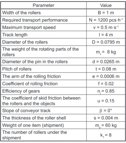
Table 1. Basic parameters of the roller conveyor
Parameter Value
Width of the rollers B = 1 m Required transport performance N = 1200 pcs·h-1 Maximum transport speed v = 0.5 m·s-1
Track length l = 4 m
Diameter of the rollers D = 0.0795 m The weight of the rotating parts of the
rollers mv = 8 kg
Diameter of the pin in the rollers d = 0.0265 m Pitch of rollers t = 0.08 m The arm of the rolling friction e = 0.0006 m Coefficient of rolling friction f = 0.02 Efficiency of gears nj = 0.85 The coefficient of skid friction between
the rollers and the objects u = 0.15 Slope of conveyor track b = 0° The thickness of the roller shell s = 0.004 m Weight of one item (shipment) mp = 60 kg The number of rollers under the
Calculating a roller conveyor in a turn
Identical input data as in the previous case was used for calculation. It is necessary to con
-sider the new transportation distance. Alternating directions are exactly 1 m apart. The internal arc diameter is 0.5 m and the outer arc diameter is 1.5 m. Using the difference of these values we calculated the mean diameter r=1m.
Circumference
O = 2πr = 2x3.14x1 = 6.28 m
l =O2 =6,282 = 3.14 m
The slope of the conveyor is δ=0°, since this is not movement of shipment on a sloped convey
-or. Transportation distance: l=3.14 m
1. speed – due to assumed manual manipulation the chosen speed is v=0.5 m.s-1 number of ship
-ments on the conveyor k=2.09≐3 pcs
2. weight of the object (shipments) per roller m=7.5 kg
3. total number of rollers on the track Z=39 rollers 4. required power for even movement P=0.351 kW 5. number of driving rollers kp
Since this is a calculation of a conveyor in an arc, it is probable that a higher resistive force will be generated on a roller as the shipment moves from one roller to the next. Therefore, the friction coefficient was doubled for this cal
-culation, kp≥5.598≐5
During the operation it was that shipments of smaller sizes are transported as well. The conveyor drove all the rollers to avoid pos
-sible misalignment of these shipments on the conveyor. This means that the value kp=8 was considered.
6. Additional power if one item stops P1=0.519 kW 7. Pc=0.87 kW
Calculation of belt conveyor for different lengths
The first part of the conveyor was 4 m long, the second 24 m, and the third returning part was 20 m long. The interconnection of the bridging belts in turns was implemented via a roller stool, since in this situation and in these directions it is not possible to use conveyor belts. The width of the belt was chosen based on the dimensions of distributed shipments. The business terms state the standard size of the bottom of the shipment as 70 x 70 cm. Practice also permits the situations
where shipments of larger sizes are distributed. Therefore, we considered the belt width B=1 m to create a reserve.
Example: Calculating 4 m long driven belt conveyor
Slope of conveyor track β=0°
1. speed – due to assumed manual manipulation the chosen speed is v=0.5 m·s-1
number of shipments on the conveyor
k=2.67≐3
Spacing of shipments tk=1.5 m
Weight of one object (shipment)
mdm=mp.k = 60 x 3=180 kg
2. The weight of the shipment per 1 meter of the conveyor length m1=mdml =1004 = 45 kg 3. The choice of belts and rolls at the specified
belt width B=1m
A belt conveyor which is resistant to mineral oils and fats, and is suitable for transportation of packaged food, wood, and plastic shipments and other small items, was selected. The belt strength is 18 N/mm. It is possible to use it in operating conditions from -10°C to +80°C. The weight of one meter at width of 1000 mm is m2 =4.6 kg. The thickness of the belt is 3.8 mm. The mini
-mum diameter of the driving drum must be 120 mm. From a safety point of view it is suitable to consider a 200 mm diameter of the driving drum. 4. Determining the main drag resistance
a) upper conveyor branch:
μ = μ1. k1= 0.02.1.07 = 0.0214 where: μ – global friction coefficient
μ1 – the friction coefficient at 20°C is in the range of 0.018–0.027, depending on the quality of production and operating conditions μ1=0.02
k1 – the coefficient respecting the effect of temperature, k1 has a value of 1.07. This
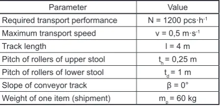
Table 2. Input values of the conveyor belt
Parameter Value
Required transport performance N = 1200 pcs·h-1 Maximum transport speed v = 0,5 m·s-1
Track length l = 4 m
value was chosen due to decrease of tem
-perature in the sorting centre in the winter season to 0°C
• mrh – the weight of the rotating rollers in the upper conveyor branch corresponding to a length of 1 m
• mrv – weight of rotating parts of one roller in the upper branch (4 kg)
• nh – number of rollers in the upper part of the stool corresponding to a length of 1 m (4 rollers)
𝑚𝑚𝑟𝑟ℎ= 𝑚𝑚𝑟𝑟𝑟𝑟. 𝑛𝑛ℎ (kg)
mrh=16 kg
𝐹𝐹𝐻𝐻ℎ = µ. 1. ɡ[(𝑚𝑚1+ 𝑚𝑚)𝑐𝑐𝑐𝑐𝑐𝑐𝑐𝑐 + 𝑚𝑚𝑟𝑟ℎ] (N) 𝐹𝐹𝐻𝐻ℎ= 0.0214𝑥𝑥4𝑥𝑥9.81[(45 + 4.6)𝑐𝑐𝑐𝑐𝑐𝑐0 + 16]= = 55.08 𝑁𝑁
b) lower conveyor branch
• mrd – weight of rotating parts of the rollers of the lower branch (4 kg)
The rollers used in the lower branch were identical to those used in the upper branch; the pitch of the lower stools rollers changed
td=1 m
𝑚𝑚𝑟𝑟𝑟𝑟=𝑚𝑚𝑟𝑟𝑟𝑟𝑡𝑡. 𝑛𝑛𝑟𝑟
𝑟𝑟 (kg)
mrd= 4 kg
𝐹𝐹𝐻𝐻𝑟𝑟= . . 𝑙𝑙. ɡ(𝑚𝑚2𝑐𝑐𝑐𝑐𝑐𝑐+ 𝑚𝑚𝑟𝑟𝑟𝑟) (N)
𝐹𝐹𝐻𝐻𝑟𝑟= 0.0214𝑥𝑥4𝑥𝑥9.81(4.6𝑐𝑐𝑐𝑐𝑐𝑐0 + 4) = 7.22 𝑁𝑁 5. Determining secondary resistances
The resistance due to bending of the belt over the drums is predicted to be 100 N per single drum.
Fv2=200 N
Similarly, the resistance due to the pin friction of drums not driven is estimated to 100 N per single drum.
Fv3=100 N
6. Determining additional resistances
Resistance to overcoming the conveyor height separately for the upper and lower branch
Fp1h = (m1+ m2)g. H (N)
Fp1h = (45+4.6)9.8x 0=0N
Fp1d = m2 . g. H (N)
Fp1d = 4.6 x 9.81 x 0= 0 N
Side line resistance – prevents falling of the shipment from the conveyor
Fp2h= μ2m2b1lBg v (N)
Fp2h= 0.645.4.9.812.0.7 = 753.77 N
• μ2 – coefficient of shear friction between the shipment and side line (0.6)
• lB – length of the side line (4 m)
• bv – light width designated by the width of the shipment (0.7)
7. Maximum belt thrust – at the point where the belt is going over the driving drum
F1=Z2+ FHh+ Fv2+ Fp1h+ Fp2h (N)
Belt thrust on the moving side of the drive drum
F2=Z2− FHd+ Fp1d (N)
Perimeter force on the driving drum
F = F1− F2= FHh+ FHd+ Fv2+ Fv3+
+Fp1h− Fp1d+ Fp2h (N)
F= F1-F2=55.08+7.22+100+200+0-0+756.77 =
= 1119.77 N
8. Required power on the drive shaft of the drum
p =F. vη (kW)
p =1119.77.0.50,6 = 0.933 kW
η – efficiency of gears (0,6)
9. Tension size (from relationship for F2) Z = 2(F2+ FHd – Fp1d) (N)
Force F2 can be expressed depending on F F2 = Fef.α1−1 (N)
F2 = 1119.772.566 − 1 = 715.53 N1 • f – friction coefficient between the belt and the
drum (f=0.3)
• α – curvature in the angle (α=180°)
Technical literature mentions a value of
ef.α = 2.566
The tension force is recommended to be in
-creased by 5–10%. Then the tension force is 751.30 N.
10. Checking the strength of the traction device Maximum belt tension after correction of tension force Z = 2(751.30 + 7.22 – 0)= 1517.04 N
F1=Z2 + FHh+ Fv2+ Fv3+ Fp1h+ Fp2h (N)
F1=1574.042 + 55.08 + 200 + 100 + 0 + 756.77 = = 1870.37 N
The allowed belt tension is 18 N for 1 mm of width, this means that the allowed tension force for a 1000 mm wide belt is FD = 18000N.
Selecting a belt conveyor
A whole range of decision making meth
-ods can be used to select a suitable solution of a belt conveyor based on the available in
-formation for individual variant solutions. The method of paired comparison seems to be suitable and relatively simple, belonging to a group of methods of multi-criterion decision making. The decision making is based on the following criteria:
A: energy demand B: investment difficulty C: safety
D: noise level in the operation E: layout and direction of conveyors
Variant solutions
• V1 – belt conveyor, turning direction to the right, placement 6 meters from the left side of the depot
• V2 – belt conveyor, turning direction to the right, placement 6 meters from the left side of the depot
• V3 – roller conveyor, turning direction to the left, placement in the central part of the depot
• V4 – belt conveyor, turning direction to the left, placement in the central part of the depot
The method of paired comparison identifies the preferential relationships of a pair of criteria. The task is to determine the number of prefer
-ences for each criterion in relation to all other
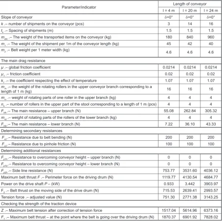
Table 3. Calculating of belt conveyor for different lengths
Parameter/indicator Length of conveyor
l = 4 m l = 20 m l = 24 m
Slope of conveyor d=0° d=0° d=0°
k .– number of shipments on the conveyor (pcs) 3 14 16
tk .– Spacing of shipments (m) 1.5 1.5 1.5
mdm .– The weight of the transported items on the conveyor (kg) 180 840 960 m1.– The weight of the shipment per 1m of the conveyor length (kg) 45 42 40
m2 .– Belt weight per 1 meter width (kg) 4.6 4.6 4.6
The main drag resistance
µ .– global friction coefficient 0.0214 0.0214 0.0214
µ1.– friction coefficient 0.02 0.02 0.02
k1.– the coefficient respecting the effect of temperature 1.07 1.07 1.07 mrh .– the weight of the rotating rollers in the upper conveyor branch corresponding to a
length of 1 m (kg) 16 16 16
mrv .– weight of rotating parts of one roller in the upper branch (kg) 4 4 4 nh .– number of rollers in the upper part of the stool corresponding to a length of 1 m (pcs) 4 4 4 FHh.– The main resistance – upper branch (N) 55.08 262.84 305.32 mrd .– weight of rotating parts of the rollers of the lower branch (kg) 4 4 4 FHd.– The main resistance – lower branch (N) 7.22 36.10 43.33 Determining secondary resistances
Fv2 .– Resistance due to belt bending (N) 200 200 200
Fv3 .– Resistance due to pinhole friction(N) 100 100 100 Determining additional resistances
Fp1h.– Resistance to overcoming conveyor height – upper branch (N) 0 0 0 Fp1d .– Resistance to overcoming conveyor height – lower branch (N) 0 0 0
Fp2h.– Side line resistance (N) 753.77 3531.60 4036.12
Maximum belt thrust F .– Perimeter force on the driving drum (N) 1119.77 4130.54 4684.77
Power on the drive shaft P – (kW) 0.933 3.442 3903.97
F2 .– Belt thrust on the moving side of the drive drum (N) 715.53 2639.41 2993.57 Tension force .– adjusted value (N) 751.30 2771.38 3143.25 Checking the strength of the traction device
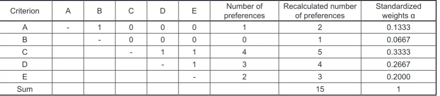
criteria of the set. The preference determination is as follows: in the upper right part of the table (upper triangle matrix) the evaluator determines for each pair of criteria, whether the criterion in the row is preferred to the criterion in the column. If yes, then it writes a value in the corresponding field, otherwise it writes 0. While evaluating this table, the number of preferences was determined for each criterion, which equals to the sum of its preferences in the row and the column of this cri
-terion. In the case of the same number of prefer
-ences for two (or more) criteria, it is necessary to consider the direction of preference of these pairs of criteria. The ranking of given criterion in the set of criteria was determined based on the number of preferences. If a criterion achieves a 0 value, it is necessary to add +1 to each criterion (see Table 4).
Calculating partial benefits of each variant through paired comparison and their conversion to standard values based on each criterion is iden
-tical to the previous procedure. Rating a variant can have a value of 0.
Table 4. Determining preferencial weights of the criterions by the method of paired comparison
Criterion A B C D E preferencesNumber of Recalculated number of preferences Standardized weights α
A - 1 0 0 0 1 2 0.1333
B - 0 0 0 0 1 0.0667
C - 1 1 4 5 0.3333
D - 1 3 4 0.2667
E - 2 3 0.2000
Sum 15 1
Table 5. Calculating partial benefits of each variant through paired comparison
Matrix A V1 V2 V3 V4 Number of preferences Usefulness ui
V1 - 0 1 0 1 0.1667
V2 - 1 0 2 0.3333
V3 - 0 0 0
V4 - 3 0.5000
Sum 6 1
Matrix B V1 V2 V3 V4 Number of preferences Usefulness ui
V1 - 0 0 0 0 0
V2 - 1 1 3 0.5000
V3 - 0 1 0.1667
V4 - 2 0.3333
Sum 6 1
Matrix C V1 V2 V3 V4 Number of preferences Usefulness ui
V1 - 0 1 0 1 0.1667
V2 - - 1 0 2 0.3333
V3 - - - 0 0 0
V4 - - - - 3 0.5000
Sum 6 1
Matrix D V1 V2 V3 V4 Number of preferences Usefulness ui
V1 - 0 1 0 1 0.1667
V2 - - 1 1 3 0.5000
V3 - - - 0 0 0
V4 - - - - 2 0.3333
Sum 6 1
Matrix E V1 V2 V3 V4 Number of preferences Usefulness ui
V1 - 1 1 1 3 0.5000
V2 - - 1 0 1 0.1667
V3 - - - 0 0 0
V4 - - - - 2 0.3333
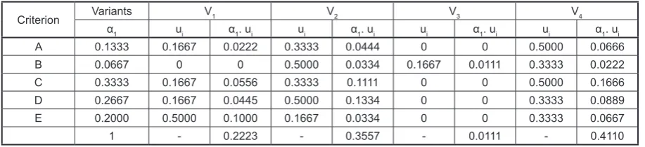
Calculating the so-called overall usefulness and selecting the most suitable variant. The selection will be implemented as a maximization function. Variant V4, i.e. the belt conveyor turning left appears to be fitting based on multicriterial assessment. Its placement is most suitable, it of
-fers similar conditions for all couriers in terms of processing received shipments as well as prepara
-tion for delivery. Appropriate condi-tions are also created for the afternoon sorting, where suitable space is created on the right side of the depot for cage containers and other necessary handling and transportation units.
CONCLUSION
The efficiency of the distribution process for providers of logistic and postal services is an important attribute of their efforts. Constant im
-provement is also motivated by high competitive pressure and customer’s demands. Innovations in processes are an important requirement to meet the declared quality as well as the efficiency of the process itself. If it is not possible to imple
-ment large invest-ment project in the operation focused on the implementation of modern au
-tomatic sorting systems, there is always room for projects of a smaller investment scale in the form of modernizing existing handling and sort
-ing systems. The paper points out the possibilities of considering suitable innovation of the sorting centre, taking into account technical, technologi
-cal, and operational aspects. Thus, the method of paired comparison was chosen to select a suitable variant, which belongs in the theory of multicrite
-rial decision-making.
Acknowledgement
VEGA 1/0721/15 – Research on the impact of postal services and telecommunication conver
-gence on regulatory approaches in the postal sector
REFERENCES
1. Andrejiova, M., Grincova, A., Marasova, D.: Mea -surement and simulation of impact wear damage to industrial conveyor belts. Wear. Engineering: Me -chanics of Materials. Vol. 368–369, 2016, 400–407. 2. Briskorn, Dirk; Emde, Simon; Boysen, Nils:
Scheduling shipments in closed-loop sortation conveyors. Journal of Scheduling. 2017. 20(1). 25–42, DOI: 10.1007/s10951–016–0498–5. 3. Conradi, Alexander; de Beauregard, Dominique
Melot; Benthaus, Burkhard; et al.: Approach for a Demand Compliant Choice of Induction Machines Used in Roller Conveyors. IEEE Conference: 20th International Conference on Electrical Machines (ICEM) Location: Marseille, FRANCE Date: SEP 02–05, 2012. pp. 1199–1205.
4. Droździel, P., Komsta, H., Krzywonos L.: An analy -sis of the relationships among selected operating and maintenance parameters of vehicles used in a transpor -tation company. Transport Problems 2011, 4(6), 93. 5. Esoso Aghor, A., Simeon, A.P.: Model design
and simulation of automatic sorting machine us -ing proximity sensor. Engineer-ing Science and Technology, an International Journal 2016, 19(3), 1452–1456, DOI: 10.1016/j.jestch.2016.04.007 6. He, D., Pang, Y., Lodewijks, G.: Speed control of
belt conveyors during transient operation. In. Powder Technology. Section of Transport Engineering and Logistics, Delft University of Technology, Mekelweg 2, Delft, Netherlands. 2016. Vol. 301, pp. 622–631 7. Kolarovszki, P.; Tengler, J.: Practical research in field
of automatic identification in automotive. In: Confer -ence: Carpathian Logistics Congress (CLC) 2015. Location: Jesenik, Czech Republic. Nov. 04–06, 2015. TANGER Ltd. pp. 92–97. Published: 2016. 8. Marasová, D. et al.: Pásová doprava. Košice.
PONT s.r.o., 2006. pp. 280.
9. Martínek, P.: Transportní zařízení. Ostrava: Ediční středisko VŠB v Ostravě, 1993, pp. 112.
10. McGuire, P. M,: Conveyors: Application, Selec -tion, and Integration (Industrial Innovation Series). CRC Press, 2009.
11. Straka, M.: Logistika distribúcie: Ako efektívne Table 6. Calculating the so-called overall usefulness for selecting the most suitable variant
Criterion Variants V1 V2 V3 V4
α1 ui α1. ui ui α1. ui ui α1. ui ui α1. ui
A 0.1333 0.1667 0.0222 0.3333 0.0444 0 0 0.5000 0.0666
B 0.0667 0 0 0.5000 0.0334 0.1667 0.0111 0.3333 0.0222
C 0.3333 0.1667 0.0556 0.3333 0.1111 0 0 0.5000 0.1666
D 0.2667 0.1667 0.0445 0.5000 0.1334 0 0 0.3333 0.0889
E 0.2000 0.5000 0.1000 0.1667 0.0334 0 0 0.3333 0.0667
dostať výrobok na trh. Vydavateľstvo: Epos, 2013. 12. Tho, TP., Thinh, NT.: Design and development of
the sorting system based on robot. In: 5th Interna -tional Conference on Control Automation and Sys -tems. 2015, pp.1639–1644.