Design and parameter optimization of spiral-dragon type straw chopping
test rig
Pengbo Ma
1,2, Liqiao Li
1,2, Baoqin Wen
1,2, Yunheng Xue
1,2, Za Kan
1,2, Jingbin Li
1,2*(1. College of Mechanical Electrical Engineering, Shihezi University, Shihezi 832000, China;
2. Key Laboratory of Northwest Agricultural equipment, Ministry of Agriculture and Rural Affairs, Shihezi 832000, China)
Abstract: In order to address the problems of large chop length, high energy consumption and poor chopping effect that were associated with a horizontal total mixed rations (TMR) mixer, a straw chopping device was designed; further, its structure and working principle were analyzed. In this study, wheat straw was chosen as the test object. The number of processing times, number of fixed blades, cutting speed, number of tooth plates and the inclined angle of the box were considered as the test factors. The standard straw length rate and average power were used as evaluation indices for conducting the orthogonal rotation combination experiment with five factors and five levels of quadratic regression. The experimental results denoted that the order of influencing factors on the standard straw length rate can be given as follows: the number of processing times, number of fixed blades, cutting speed, number of tooth plates and inclined angle of the box. The order of the influence of each factor on the average power can be given as follows: the cutting speed, number of fixed blades and number of tooth plates. Further, the optimum structural and working parameters of the device can be determined as follows: linear cutting speed of 17-20 m/min, box inclined angle of 70°-80°, 20-23 fixed blades, 5-6 processing times and 4-7 tooth plates. Under such a circumstance, the standard straw length rate reached up to 70.5%-77.4% and the average power was low at 5.8-7 kW. The results can be used as reference for designing a chopping device for a TMR mixer.
Keywords: total mixed rations, straw, chopping device, parameter optimization
DOI: 10.25165/j.ijabe.20201301.4927
Citation: Ma P B, Li L Q, Wen B Q, Xue Y H, Kan Z, Li J B. Design and parameter optimization of spiral-dragon type straw chopping test rig. Int J Agric & Biol Eng, 2020; 13(1): 47–56.
1 Introduction
Large-scale breeding is an important meat sheep breeding method because of its advantages of high rate of domestic animals for sale, remarkable economic benefits and easy to manage[1-3]. Total mixed rations (TMR) denotes the balanced diet that can be obtained based on the nutritional requirements of ruminants at different stages of growth and development to ensure a balanced feed intake for ruminants, improve the utilisation rate of crude feed, facilitate production of sheep breeding, environmental control and satisfy the requirements of modern meat sheep standardisation and intensification. Mechanised production uses the TMR breeding technology[4,5], which is considered to be an effective methodology for meat sheep breeding to realise the transition from traditional to modern, and the development of a suitable TMR mixer is considered to be the key for the application of this technology[6-8].
A TMR mixer is an integrated machine that can perform the functions of cutting, kneading and mixing. It is mainly divided into horizontal and vertical structure types. The vertical type
Received date: 2019-01-19 Accepted date: 2019-12-10
Biographies: Pengbo Ma, Master candidate, research interests: livestock machinery, Email: [email protected]; Liqiao Li, Lecturer, research interests: livestock machinery, Email: [email protected]; Baoqin Wen, PhD candidate, Associate Professor, research interests: livestock machinery, Email: [email protected]; Yunheng Xue, Master, research interests: livestock machinery, Email: [email protected]; Za Kan, Professor, research interests: livestock machinery, Email: [email protected].
*Corresponding author: Jingbin Li, PhD, Professor, research interests: livestock machinery. College of Mechanical Electrical Engineering, Shihezi University, Shihezi 832000, China. Tel: +86-13779206996, Email: ljb8095@ 163.com.
mainly comprises single helix and double helix, whereas the horizontal type comprises the spiral type (single helix, double helix, triple helix and four-helix), pull-wheel type and chain plate type, which is considered to be the main type[9,10]. The vertical TMR mixer can easily process large round or square bales of forage, leaving almost no material in the container after unloading. The number of moving blades that have been assembled on the horizontal TMR mixer is relatively large, thereby enabling the forage to be cut rapidly. In addition, the total height of the box of horizontal TMR mixer is relatively low. Therefore, entering and leaving some sheep houses with considerable height requirements and the addition of artificial forage are convenient. Further, the horizontal TMR mixer is extensively used in large-scale meat sheep breeding in Xinjiang.
Animal husbandry has matured in developed countries in terms of technology and manpower. Thus, their proportion of technology development and application of TMR mixer far outpaces that of China[11-15].The development rate of domestic animal husbandry has been increasing year by year, and the usage of animal husbandry machinery products have led in new development opportunities. However, the research and application of the key technologies of TMR mixer are currently immature[16,17], thereby restricting the development of the TMR
breeding process in China. Thus, it is essential to improve and perfect this technology.
designing the TMR mixer.
2 Structure and principle
2.1 Structure
The test rig mainly comprises a box body, feed port, spiral mixing dragon, moving blade, fixed blade, movable side plate, tooth plate, outlet, frame and transmission system. The power is provided by a 7.5 kW three-phase asynchronous motor and a gear reducer with a speed ratio of 1:35, as depicted in Figure 1.
1. Fixed blade 2. Box body 3. Plum blade 4. spiral mixing dragon 5. Inputs 6. Coupling 7. Electric motor 8. Frame 9. Movable side plate 10. Tooth plate 11. Pulling board 12. Outlet
Figure 1 Schematic diagram of the structure of the straw chopping test rig
2.2 Working principle
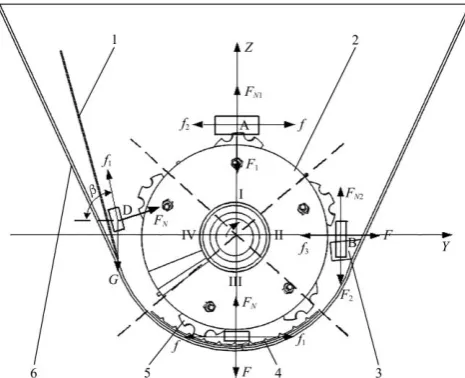
The chopping process of the straw is divided into four zones (zone I, II, III and IV) in the spatial clockwise direction as depicted in Figure 2.
1. Movable side plate 2. Spiral mixing dragon 3. Fixed blade 4. Tooth plate 5. Plum blade 6. Box body
Note: F: pressure of the mixing dragon on straw; f: friction force of the spiral mixing dragon on straw; Fn: supporting capacity of box to straw; f1: friction force
of box against straw; F1: force between straws; f2: friction force between straws;
g: straw gravity; F2: shear force; Fn1: the support capacity of spiral mixing
dragon to straw; Fn2: the support force of fixed blade to straw; f3: the friction
force of fixed blade on straw; β: the inclined angle of the box.
Figure 2 schematic diagram of stress in the process of straw chopping process
When the straw is added from zone I, the straw moves to zone II under the action of friction force f. When the straw moves to the top of the fixed blade, the movement of the straw is terminated
and a layer of straw is accumulated above the fixed blade. Under the action of the support force fn2 and shear force f2 of the fixed
blade, the straw is cut and broken, and the broken straw moves to the bottom of the box under the action of the friction force f and the pressure f of the screw blade. Further, the distance between the blade and the bottom of the box initially decreases and then increases. Thus, the friction force of the straw extrusion layer between the bottom of the box and the spiral mixing dragon initially increases and then decreases. The chopping effect initially strengthens and subsequently weakens. As the spiral mixing dragon continues to rotate, moreover, under the action of friction force f, the straw is sprayed to the upper left, and the extruding layer of the straw is broken. When the inclined angle of the box is considerably large, the effect of straw throwing is perfect. however, the spiral mixing dragon cannot exert force on the straw to perform a circular motion; the straw can only move along the wall of the box to the outlet. When the inclined angle of the box becomes considerably small, the effect of straw throwing is not obvious, and straw chopping is not uniform.
3 Design of key parts
3.1 Spiral mixing dragon
Spiral mixing dragon is the main working part of the straw chopping test rig, as depicted in Figure 3.
Figure 3 Schematic diagram of spiral mixing dragon The structure is uniaxial and horizontal and six helical blades are welded to the sleeve of the spiral mixing dragon. Moreover, it should satisfy the following formulas:
d=(0.02
~
0.4)L (1)2
47
Q D s n (2)
1
sK D (3)
max
30K 2g n
D
(4)
where, d is the inner diameter of spiral blade, mm; L is the total length of spiral mixing dragon, mm; Q is the screw conveyor capacity, t/h; D is the outer diameter of spiral blade, mm; s is the spiral blade pitch, mm; n is the speed of spiral mixing dragon, r/min; ψ is the coefficient of admission; λ is the material bulk density, kg/m3; ξ is the conveying coefficient of screw conveyor, which is related to the helix angle; K1 is the filling coefficient; K is
the material coefficient of colligation.
The wall thicknesses of the helical blades are 5 mm and five plum blades are mounted on each helical blade. The total length, effective chop length, internal diameter, outer diameter and pitch are 1800, 1500, 114, 300 and 240 mm, respectively, according to the Agricultural Machinery Design Manual. Further, the value of
ψ, λ, ξ, K1, K are defined as 0.5, 60, 0.7, 0.8, 0.5 in this study. To
ensure that the straw is smoothly discharged from the outlet, three switch-plates is welded at the end of the spiral mixing dragon.
3.2 Tooth plate
on the surface. The tooth plate, the spiral mixing dragon, the fixed blade, the side wall of the box and the moving side plate constitute the chopping chamber. The chopping chamber is the main area of straw comminution and chopping. The tooth plate is used to enhance the crushing ability and is located in the lower part of the chopping chamber. The tooth plate hinders the movement of feed circulation, reduces the speed of feed movement in the chopping room and enhances the impact, shear, rubbing and friction of materials. The working face of the tooth plate is perpendicular in the tangential direction of the turning direction of the spiral mixing dragon, thereby enhancing the chopping effect.
Figure 4 Sectional drawing of tooth plate
The tooth plate is welded at the bottom of the box with a length of 1400 mm. The profile of the tooth plate is depicted in Figure 4. The parameters of the geometric model of the tooth plate can be given as follows: the outer surface arc radius R and the inner surface arc radius r are 385 and 380 mm, respectively. The inner surface contains the rack, and the rack section is an isosceles triangle with an equal side length a of 5 mm, an angle θ of 78° and an angle φ of 90° between the two ends of the plate section and the centre o.
3.3 Movable side plate
The side wall of the box is welded with a self-designed movable side plate whose angle can adjust to change the inclined angle of the box and to change the size of the chopping space.
The inclined angle of the box is the angle between the side plate of the box and the horizontal plane. According to the analysis of the chopping process of the straw, the straw-extruded layer is formed between the spiral mixing dragon and the bottom shell of the box body. With the rotation of the dragon, the gap between the side plate of the box body and the screw-stirring dragon increases gradually. The straw-extruding layer scatters to the side plate of the box, and the straw extruded layer is broken. The tilting angle of the box directly influences the effect of straw throwing. The inclined angle of the box is considerably small; further, the gap between the spiral mixing dragon and the side plate of the box is considerably large, and the total amount of moving materials in the space decreases with the spiral mixing dragon. Further, the total amount of linear movement along the side plate of the box to the outlet increases, thereby resulting in the poor chopping effect of the straw. The tilting angle of the box body is considerably large, and the throwing effect of the straw is weakened when it is rotated with the spiral mixing dragon, resulting in uneven chopping of the straw. The angle range of the movable side plate is determined to be 63°-87° by pre-experiment, and its position in the box is depicted in Figure 1.
4 Experiment
4.1 Experimental method
An analysis of the working process of reference[21] and the test
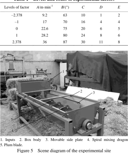
rig depicted that the main factors which affect the chopping performance of the test stand included cutting speed (A), the inclined angle of the box (B), the number of fixed blades (C), the number of tooth plate (D), the number of processing times (E). The test factors should be coordinated according to the process analysis of the pre-experimental processing and production practice. By considering the characteristics of each experimental design method, the experimental method of quadratic regression orthogonal rotational combination with five factors of five levels each was adopted. The levels and codes of experimental factors was shown in Table 1 and the scene diagram of experimental site was depicted in Figure 5.
Table 1 Levels and codes of experimental factors
Levels of factor A/m·min-1 B/(°) C D E
–2.378 9.2 63 10 1 2
–1 17 70 16 4 4
0 22.6 75 20 6 5
1 28.2 80 24 8 6
2.378 36 87 30 11 8
1. Inputs 2. Box body 3. Movable side plate 4. Spiral mixing dragon 5. Plum blade.
Figure 5 Scene diagram of the experimental site
4.2 Experimental material and evaluation index
4.2.1 Materials and instruments for experiment
In this experiment, the experimental instruments included the straw chopping test rig, NVF2G-7.5/TS4 multi-function inverter (Zhengtai universal type), MD2K-2 electronic balance (precision 0.1 g, Shanghai Tianping instrument Factory), etc.
Moreover, the wheat straw was bundled in Shihezi, Xinjiang. The variety of wheat straw was Xinchun 6. The size of straw bundle (length × width × height) was 900 mm × 600 mm × 400 mm. The moisture content was approximately 17.86%.
4.2.2 Evaluation index
The standard straw length rate and average power were selected as the evaluation indices in this experiment.
(1) Standard straw length rate
According to JB/T 9707.2-1999, the standard straw length rate was the percentage of the total quality of standard straw to the total quality of sample straw. Further, the standard straw was the straw which length was 2/3-6/5 times to the designed length after chopping process. For meat sheep, the appropriate length of straw was 8-25 mm; further, the length of standard straw was 5.3-30 mm. To ensure convenience of screening, the standard straw length was chosen as 5-30 mm.
100 g was obtained from each sample. The total mass of the sample my was weighed using an electronic balance; further,
sample sieved with standard sieve which constituted with aperture
Φ19 mm, Φ8 mm, Φ5 mm and chassis. The length of straw larger than 30 mm on each sieve and the straw in the chassis were selected and the remaining straw quality mc was weighed using an
electronic balance. Finally, the average value of the three groups was calculated as the standard straw length rate. The formula for the standard straw length rate was
100% c c
y
m S
m
(5)
where, Sc is the standard straw length rate, %; mc is the total quality
of standard straw, g; my is the total quality of sample straw, g.
(2) Average power
Power was an important index for measuring the quality of the spiral straw chopping device. Power was measured using an NVF2G-7.5/TS4 multi-function inverter, and the initial power P1,
the working power P2 and the finial power P3 of the chopping test
rig were recorded, and the average value was obtained. The formula for calculating power was
1 2 3
1
( )
3
P PP P (6)
where, P is the average power, kW; P1 is the initial power, kW; P2
is the working power, kW; P3 is the final power, kW.
Y=77.34+2.45A+2.07B+3.92C+2.30D+4.53E+1.64AB–1.92AC–
2.36AD–2.38AE–3.13BC–0.83BD–1.98BE+0.49CD–1.23CE– 2.60DE–2.78A2–2.37B2–5.16C2–1.28D2–3.04E2 (7)
P=7.57+1.60A+0.24B+0.50C+0.78D+0.14E+0.27AB–0.17AC–
0.066AD–0.13AE–0.35BC+0.17BD+0.13BE+0.33CD–0.022CE+ 0.053DE+0.19A2–0.089B2–0.019C2–0.089D2+0.087E2 (8)
4.3 Experimental result analysis
4.3.1 Regression model and variance analysis
The standard straw length rate and average power regression models were analyzed using the Design-Expert 8.0 software. The results were presented in Equations (7) and (8) and Table 2.
According to the analysis of the variance of the two evaluation indices presented in Table 2, the p value of the two models was considered to be extremely significant; however, the loss item was not significant, indicating that the influence of each factor on the test index was very significant and that the model was suitable. The model determination coefficients were also obtained by the Design-Expert 8.0 software as R1
2
=0.9062 and R2 2
=0.9200. The results denoted that the regression model fitted well with the experimental results and that it could be used to predict the change of standard straw length rate and average power in the process of straw chopping.
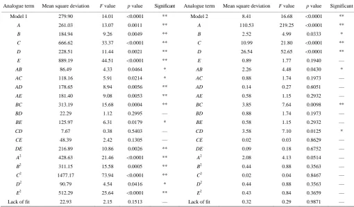
Table 2 Variance analysis of the regression model for the evaluation index
Analogue term Mean square deviation F value p value Significant Analogue term Mean square deviation F value p value Significant
Model 1 279.90 14.01 <0.0001 ** Model 2 8.41 16.68 <0.0001 **
A 261.03 13.07 0.0011 ** A 110.53 219.25 <0.0001 **
B 184.94 9.26 0.0049 ** B 2.52 4.99 0.0333 *
C 666.62 33.37 <0.0001 ** C 10.99 21.80 <0.0001 **
D 228.51 11.44 0.0021 ** D 26.54 52.65 <0.0001 **
E 889.19 44.51 <0.0001 ** E 0.89 1.77 0.1940 —
AB 86.49 4.33 0.0464 * AB 2.26 4.48 0.0430 *
AC 118.16 5.91 0.0214 * AC 0.88 1.74 0.1973 —
AD 178.65 8.94 0.0056 ** AD 0.14 0.27 0.6051 —
AE 181.40 9.08 0.0053 ** AE 0.58 1.15 0.2932 —
BC 313.19 15.68 0.0004 ** BC 3.85 7.64 0.0098 **
BD 22.29 1.12 0.2995 — BD 0.88 1.74 0.1973 —
BE 125.97 6.31 0.0179 * BE 0.58 1.15 0.2932 —
CD 7.67 0.38 0.5403 — CD 3.58 7.10 0.0125 *
CE 48.39 2.42 0.1305 — CE 0.02 0.03 0.8629 —
DE 216.89 10.86 0.0026 ** DE 0.09 0.18 0.6752 —
A2 428.63 21.46 <0.0001 ** A2 2.08 4.13 0.0514 —
B2 311.15 15.58 0.0005 ** B2 0.44 0.88 0.3563 —
C2 1477.17 73.94 <0.0001 ** C2 0.02 0.04 0.8467 —
D2 90.79 4.54 0.0416 * D2 0.44 0.88 0.3563 —
E2 512.29 25.64 <0.0001 ** E2 0.43 0.84 0.3659 —
Lack of fit 22.93 2.15 0.1513 — Lack of fit 0.32 0.29 0.9871 —
Note: ** (p < 0.01) is extremely significant. * (p<0.05) is significant. — (p>0.05) is not significant. Model 1 is the standard straw length rate regression model, and model 2 is the average power regression model.
4.3.2 Analysis of the influence of various factors on the rate of standard straw length rate
(1) Single-factor analysis
The effects of various factors on the standard straw length rate were investigated in this study. The results were presented in Figure 6.
With an increase in the cutting speed, the number of fixed blades, the number of processing times, the inclined angle of the
the box, the total straight-line motion of the straw along the wall of the box gradually decreased; moreover, the total amount of movement of straw in the space, the chopping effect and the rate of standard straw length rate increased with an increase in the inclined angle of the box. The gap between the spiral mixing dragon and the box body increased, the chopping effect on the straw improved, the fine powder ratio increased and the standard straw length rate decreased when the inclined angle of the box increased gradually.
Figure 6 Effects of various factors on the length of straw standard straw
(2) Analysis of the influence law of two factors
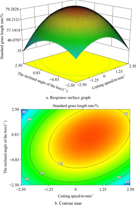
The number of fixed blades, the number of tooth plates and the number of processing times were maintained to be 0 level, and the response surface and contours were drawn using the Design-Expert 8.0 software, as presented in Figure 7.
a. Response surface graph
b. Contour map
Figure 7 Effects of cutting speed and the inclined angle of the box on the straw standard straw rate
Figure 7 indicated that the standard straw length rate initially increased and subsequently decreased with an increase in the rotation speed of the spiral mixing dragon, the standard straw length rate initially increased and subsequently decreased with an increase in the inclined angle of the box and the standard straw length rate reached the maximum value 77% at the level of 0 or so. This occurred because the straw which at the bottom of the box was driven by the spiral mixing dragon and thrown to the sideboard of the box during the chopping process; further, the falling straw and the sprinkled straw form a convection mixture, thereby enhancing the uniformity of chopping. The gap between the spiral mixing dragon and the side plate of the box decreased, the throwing effect of straw became weakened with an increase in the inclined angle of the box. The chopping effect improved and the standard straw length rate gradually decreased at a high cutting speed.
Figure 8 depicted that the inclined angle of the box, the number of tooth plates and the number of processing times were maintained to be 0 level. When the number of fixed blades was maintained constant, the standard straw length rate initially increased and subsequently decreased with an increase in the cutting speed. At a constant cutting speed, with an increase in the number of fixed blades, the standard straw length rate initially increased and then decreased because the action frequency between the blade and the fixed blade became faster with an increase in cutting speed; further, the chopping effect on the straw was strengthened. When the number of fixed blades and cutting speed increased to a certain value, the growth rate of the fine powder of the straw became higher than that of the standard straw length rate, and the standard straw length rate showed a downward trend.
a. Response surface graph
b. Contour map
As can be observed in Figure 9, the angle of inclination of the box, the number of fixed blades and the number of processing times were maintained to be 0 level. With an increase in the number of tooth plates, the speed of the straw movement in the circumferential direction decreased, the impact of the straw increased and the effects of shear, rubbing and friction were enhanced. With an increase in the number of tooth plates, when the straw was kneaded and cut to a certain length, the growth rate of fine powder was larger than the standard straw length rate; further, the standard straw length rate decreased slowly. The growth rate of fine powder increased when compared to the standard straw length rate with an increase in the cutting speed of the spiral mixing dragon. The frequency of straw chopping was accelerated; further, the chopping effect on the straw was enhanced. Thus, the standard straw length rate initially increased and subsequently decreased.
a. Response surface graph
b. Contour map
Figure 9 Effects of cutting speed and the number of tooth plate on the straw standard straw rate
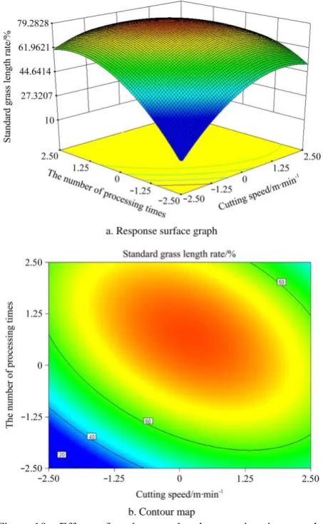
Figure 10 depicted that the box inclined angle, the number of fixed blades and the number of tooth plates were maintained to be 0 level. The standard straw length rate initially increased and subsequently decreased with an increase in the cutting speed and processing times. The chopping time of the straw increased with an increase in processing times. As the standard straw length rate increased, the fine powder rate also increased. The growth rate of fine powder was observed to be higher than the standard straw length rate growth rate while conducted chopping for a certain time. Subsequently, the standard straw length rate decreased. The impact force of the spiral mixing dragon increased with an increase in the cutting speed. Further, the effect of chopping of straw was
enhanced. Thus, the standard straw length rate initially increased and subsequently decreased slowly.
a. Response surface graph
b. Contour map
Figure 10 Effects of cutting speed and processing times on the straw length rate
Figure 11 depicted that the cutting speed, the number of tooth plates and the number of processing times were maintained to be 0 level. The standard straw length rate initially increased and subsequently decreased with an increase in the inclined angle of the box and the number of fixed blades. The gap between the box and the spiral mixing dragon decreased, the thrown straw fell faster and the chopping effect on the straw was enhanced with an increase in the inclined angle of the box. The amount of straw increased with the curve motion of the spiral mixing dragon in space with an increase in the number of fixed blades. When the straw was cut to a certain extent, the fine powder rate of the straw increased; further, the standard straw length rate decreased.
a. Response surface graph
b. Contour map
Figure 11 Effects of the number of tank and the number of fixed blades on the standard straw length rate of straw
a. Response surface graph
b. Contour map
Figure 12 Effects of the angle of the box and the number of processing times on the length of the straw standard straw
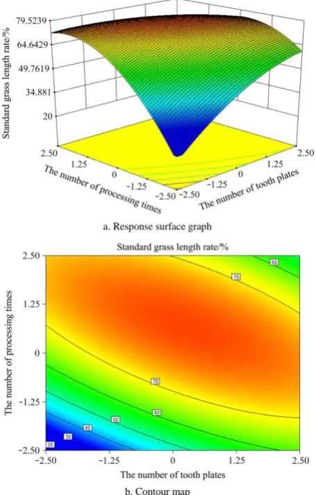
Figure 13 depicted that the cutting speed, the inclined angle of the box and the number of fixed blades were maintained to be 0 level. Straw chopping initially increased and subsequently decreased with an increase in the number of tooth plates and the number of processing times. The chopping effect on the straw and the rate of standard straw length rate increased when the number of tooth plates and processing times began to increase from a low level. Further, the chopping effect on the straw increased when the number of tooth plates and the number of processing times reached to a high level. Subsequently, when the number of tooth plates and the number of processing times reached a high level, the chopping effect of the tooth plate on the straw decreased, the processing times and the fine powder rate of the straw increased and the standard straw length rate decreased.
a. Response surface graph
b. Contour map
Figure 13 Effects of the number of tooth plates and the number of processing times on the length of the straw standard straw 4.3.3 Analysis of the influence of various factors on the rate of average power
(1) Single-factor analysis
subsequently scattered in the box, and the power consumption increased. The rubbing effect of the straw in the bottom of the box was enhanced and the power consumption increased with an increase in the number of tooth plates and fixed blades.
Figure 14 Effects of each factor on the average power consumption
(2) Analysis of the influence law of two factors
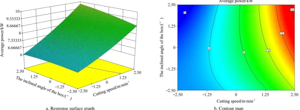
As can be observed from Figure 15, the number of fixed blades, the number of tooth plates and the number of processing times were maintained to be 0 level, and the average power increased
with the cutting speed and the inclined angle of the box because of the increase in the cutting speed. Therefore, the powers P1, P2
and P3 consumed in the straw chopping process increased. Thus,
the average power increased with an increase in the cutting speed. However, the gap between the inclined angle of the box and the spiral mixing dragon decreased with an increase in the inclined angle of the box; further, the power P1 and P2 in the middle period
of straw chopping increased. Thus, the average power increased with an increase in the inclined angle of the box.
As can be observed from Figure 16, the cutting speed, the number of tooth plates and the number of processing times were maintained to be 0 level. The average power consumed with the increase in the inclined angle of the box increased when the number of fixed blades was maintained to be constant. The average power increased with the increase in the number of fixed blades when the inclined angle of the box was fixed. The average consumed power increased because the increase in the inclined angle of the box which made the consumption of P1, P2 and the
average power in the chopping process of the straw increased. The processing times of straw were observed to increase with an increase in the number of blades. During the process of straw chopping, the consumption of P2 became larger. Thus, the
average power increased.
a. Response surface graph b. Contour map
Figure 15 Effects of cutting speed and the inclined angle of the box on the average power consumption
a. Response surface graph b. Contour map
Figure 16 Effects of the quantity of the box and the number of fixed blades on the average power consumption
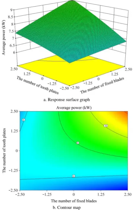
Figure 17 depicted that the cutting speed, the inclined angle of the box and the number of processing times were maintained to be 0 level. Furthermore, the average power increased with an
was enhanced and P1 and P2 increased during the process of straw
chopping with an increase in the number of fixed blades. Thus, the average power P increased.
a. Response surface graph
b. Contour map
Figure 17 Effects of the number of fixed blades and the number of plates on the average power consumption
4.4 Experimental optimization
To solve the problems of large chop length and high energy consumption of the test rig while Set the parameter as follows: the cutting speed was 9.2-36 m/min, the number of tooth plates was 1-11, the number of fixed blades was 10-30, the inclined angle of box was 63°-87° and the number of processing time was 2-8. Further, the targets were set as the standard straw length rate objective function was set to the maximum value and the average power objective function was set to the minimum value by Design-Expert 8.0 software. The optimal parameter combination was observed based on the condition that the two objective functions were simultaneously close to each other. The optimized results were given as follows: cutting speed of 17-20 m/min, 4-7 tooth plates, 20-23 fixed blades, box inclined angle of 70°-80°, the number of processing times was 5-6, standard straw length rate of 70.5%-77.4% and average power of 5.8-7 kW.
To further verify the reliability of the optimized results, a cutting speed of 18.2 m/min, 4 tooth plates, 21 fixed blades, a 74° inclined angle of the box and 6 processing times were selected based on the combination of the aforementioned optimal test factors. The experimental results denoted that each index satisfied the requirements and little difference between two repeated tests which was close to the theoretical value. These observations denoted that the optimized results and the model were reliable.
5 Conclusions
1) To reveal the chopping process of the TMR mixer, a spiral straw chopping test rig was designed, and the tooth plate was installed at the bottom of the box to enhance the effect of chopping. The processed straw was considered to be favourable for breeding.
2) The main factors that influence straw chopping were determined through the straw chopping test. The main factors that affected the standard straw length rate and average power were the number of processing times, the number of fixed blades, the cutting speed, the number of tooth plates and the inclined angle of the box. The optimal range of the working parameters can be determined as follows: cutting speed of 17-20 m/min, 4-7 tooth plates, 20-23 fixed blades, inclined angle of 70°-80° the box and 5-6 processing times. Under such a circumstance, the standard straw length rate was 70.5%-77.4%, and the average power was 5.8-7 kW.
3) The blade and the spiral mixing dragon exhibited wear in the whole experimental process. The factors that cause wear should be analyzed and improvements should be made to prolong the service life of the straw chopping device in the following research.
Acknowledgements
The authors acknowledge that this work was financially supported by the National Natural Science Foundation of China (No.51775358), the Young and Middle-aged Leaders in Science and Technology Innovation (No.2016BC001), Third Division Meat
Sheep Breeding Mechanized Science and Technology
Commissioner Innovation and Entrepreneurship Demonstration (No.2016CA002) and the Shihezi University Science and
Technology Achievements Transformation Project
(No.CGZH201601).
[References]
[1] Gusmao J O, Danes M A C, Casagrande D R. Total mixed ration silage containing elephant straw for small-scale dairy farms. Straw and Forage Science, 2018; 73(3): 717–726.
[2] Santana A, Cajarville C, Mendoza A, Repetto J L. Combination of legume-based herbage and total mixed ration (TMR) maintains intake and nutrient utilization of TMR and improves nitrogen utilization of herbage in heifers. Animal, 2017; 11(4): 616–624.
[3] Gao Z J, Li H, Meng H W. Precise breeding mode of concentrate based on total mixed ration breeding technology. Transactions of the CSAE, 2013; 29(7): 148–154. (in Chinese)
[4] Zhong R Z, Fang Y, Zhou D W. Pelleted total mixed ration improves growth performance of fattening lambs. Animal Feed Science and Technology, 2018; 242: 127–134.
[5] Perez-Ruchel A, Repetto J L, Cajarville C. Supplementing high-quality fresh forage to growing lambs fed a total mixed ration diet led to higher intake without altering nutrient utilization. Animal, 2017; 11(12): 2175–2183.
[6] Wang D F, Jiang Y Y. Experimental study on two-axis horizontal total mixed ration mixer. Transactions of the CSAE, 2006; 22(4): 85–88. (in Chinese)
[7] Yu K Q, Li L Q, H X, Wang D F, Zhang Q C, Na M J. Experimental design and mechanism analysis of runner type total mixed ration mixer. Transactions of the CSAM, 2015; 46(7): 109–117. (in Chinese)
[8] Bisaglia C, Romano E. A novel magnetic device for intercepting metal foreign objects in total mixed rations. Applied Engineering in Agriculture, 2017; 33(1): 55–61.
[9] Li L Q, Wang D F, Li C. Mixing process analysis and performance experiment of rotary ration mixer. Transactions of the CSAM, 2017; 48(8): 123–132. (in Chinese)
[11] Chen Y H, Tian F Y, Yan Y F, Song Z H, Li F D, Zhang Z L. Research progress of domestic and foreign TMR breeding technologies and mixers. Journal of Chinese Agricultural Mechanization, 2017; 38(12): 19–29. (in Chinese)
[12] Alhidary I, Abdelrahman M M, Alyemni A H. Characteristics of rumen in Naemi lamb: Morphological changes in response to altered breeding regimen. Acta Histochemica, 2016; 118(4): 331–337.
[13] Alvarez-Rodriguez J, Monleon E, Sanz A. Rumen fermentation and histology in light lambs as affected by forage supply and lactation length. Research in Veterinary Science, 2012; 92(2): 247–253.
[14] Olafadehan O A, Adewumi M K, Okunade S A. Effects of breeding tannin-containing forage in varying proportion with concentrate on the voluntary intake, haematological and biochemical indices of goats. Trakia Journal of Sciences, 2014; 12: 73–81.
[15] Yuan X J, Wen A Y, Wang J. Fermentation quality, in vitro digestibility and aerobic stability of total mixed ration silages prepared with whole-plant corn (Zea mays L.) and hulless barley (Hordeum vulgare L.) straw. Animal Production Science, 2018; 58(10): 1860–1868.
[16] Li L Q, Wang D F, Li C, Li D H, Jiang Z G, Ping Z Y. Design and experimental optimization of combined-type ration mixer of drum and blade. Transactions of the CSAM, 2017; 48(10): 67–75. (in Chinese) [17] Wang W W, Li J C, Chen L Q, Qi H J, Liang X T. Effects of key
parameters of straw chopping device on qualified rate, non-uniformity and power consumption. Int J Agric & Biol Eng, 2018; 11(1): 122–128. [18] Blanco C, Giraldez F J, Prieto N. Total mixed ration pellets for light
fattening lambs: effects on animal health. Animal, 2015; 9(2): 258–266. [19] Chen L, Guo G, Yu C Q, Zhang J, Shimojo M, Shao T. The effects of
replacement of whole-plant corn with oat and common vetch on the fermentation quality, chemical composition and aerobic stability of total mixed ration silage in Tibet. Animal Science Journal, 2015; 86(1): 69–76. [20] Leibovich H, Zenou A, Yosef E. Digestibility by lambs and nutritive
value for lactating ewes of a total mixed ration containing Cephalaria joppensis silage as wheat silage substitute. Small Ruminant Research, 2013; 112(3): 97–102.
[21] Xue Y H, Li J B, Wen B Q, Kan Z. The rubbing cutting mechanism analysis and parameter optimization of the dragon-type straw cutting device. Journal of Agricultural Mechanization Research, 2018; 40(12): 157–161. (in Chinese)
[22] Li L Q, Wang D F, Yang X. Study on round rice straw bale wrapping silage technology and facilities. Int J Agric & Biol Eng, 2018; 11(4): 88–95.