www.adv-radio-sci.net/14/71/2016/ doi:10.5194/ars-14-71-2016
© Author(s) 2016. CC Attribution 3.0 License.
A GPS based fawn saving system using relative distance and
angle determination
A. Ascher, M. Eberhardt, M. Lehner, and E. Biebl
Associate Professorship of Microwave Engineering, Technical University of Munich, Munich, Germany
Correspondence to:A. Ascher ([email protected])
Received: 17 December 2015 – Revised: 26 February 2016 – Accepted: 28 February 2016 – Published: 28 September 2016
Abstract.Active UHF RFID systems are often used for iden-tifying, tracking and locating objects. In the present publica-tion a GPS- based localizapublica-tion system for saving fawns dur-ing pasture mowdur-ing was introduced and tested. Fawns were first found by a UAV before mowing began. They were then tagged with small active RFID transponders, and an appro-priate reader was installed on a mowing machine. Conven-tional direction-of-arrival approaches require a large antenna array with multiple elements and a corresponding coher-ent receiver, which introduces a large degree of complexity on the reader-side. Instead, our transponders were equipped with a small GPS module, allowing a transponder to deter-mine its own position on request from the reader. A UHF link was used to transmit the location to a machine- mounted reader, where a second GPS receiver was installed. Using in-formation from this second position and a machine- mounted magnetometer for determining the relative north direction of a vehicle, relative distance, and angle between GPS receivers can be calculated. The accuracy and reliability of this novel method were tested under realistic operating conditions, con-sidering critical factors such as the height of grass, the lying position of a fawn, humidity and geographical area.
1 Introduction
The main period for fawns to be born is in the spring, be-tween the end of April and middle of June (Rieck, 1955). When giving birth, does seek calm and protected areas on the edges of woods with high grass as a visual cover, to pro-tect newborn fawns against natural threats. Unfortunately, this birth period coincides with the first cut of the pasture when farmers start mowing for animal forage. To make mat-ters worse, fawns instinctively lie flat and silent on the ground
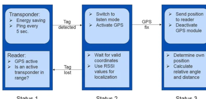
The system developed in this research avoided the use of con-ventional direction-of-arrival techniques to allow it to be in-tegrated with different types of mowing machine. Systems requiring wide antenna structures and large receiver setups connected to them make this challenging, because of the dif-ferent shapes and sizes of mowing machines from difdif-ferent manufacturers. A further goal was that the system should be able to communicate with the agricultural machine using the standard ISOBUS protocol. The envisaged functionality is shown in Fig. 1. The transponder on a marked fawn would re-veal its own position on request from the reader. After a valid set of coordinates was identified, this information would be send to the machine mounted reader, where further data pro-cessing is performed.
The hardware comprised a transponder for tagging the fawn and a reader integrated into the agricultural machine. A number of prerequisites have to be fulfilled.
The transponder presented in Ascher et al. (2015) had to comply a small form factor of less than 30 mm×50 mm. A transponder larger than this, cannot be attached to the fawn without disturbing its natural behavior. The GPS module had to have a lifetime of at least four weeks, over which period it had to perform a minimum of three GPS fixes. The time taken to make valid GPS coordinates available had to be less than 60 s, and the communication range of the UHF data link had to be at least 200 m to guarantee that the mowing ma-chine could be stopped in time. The realized transponder is shown in Fig. 2, both in close-up and attached to a fawn. We also wanted to ensure that the transponder had no ma-jor environmental impacts. Because batteries need to be used in active UHF transponders, these have to be chosen while taking account of their flammability and environmental sus-tainability. After comparing batteries based on different tech-nologies, zinc air (ZnO) primary cells were selected as the most suitable, as they are capable of providing a peak cur-rent of over 100 mA which is drawn from the GPS module during acquisition, are nonflammable, and produce compar-atively safe chemical reaction products.
The transponder comprised a high efficiency GPS module (Origin), a CC1110 System on a Chip (SoC) with an
inte-Figure 3.The machine mounted reader.
grated UHF frontend for the data link, chip antennas for the UHF- and GPS L1 band to meet the size constraints, and four stacked ZnO batteries at the back of the transponder as a power supply.
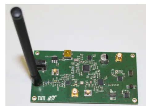
For integration with the mowing machine, the compa-rably small reader board shown in Fig. 3 was developed. The reader itself used the same SoC as the transponder, but includes an additional variable gain amplifier (VGA) to enhance both the receiver sensitivity and the transmit-ting power. For communication with the mowing machine, an FTDI based USB interface was available. The board had a 12 V operating voltage, matching the standard on-board power supply of agricultural machinery. For localization, an additional GPS module was mounted on the roof of the ma-chine and connected to the reader board using UART. It is possible to replace this supplementary GPS module with the high precision DGPS which is often implemented in agri-cultural machines for lane detection. The system was there-fore straightforward to integrate into the existing communi-cation protocols of the mowing machines, whilst providing high precision localization.
Figure 4.System flowchart.
the vehicle-mounted GPS continuously updates its position and seeks any active transponder is in range sending its ID. This is the main operating state of the system, in which the transponder draws an average current of 60 µA. Status 2 is the phase in which a transponder is detected and communicates with the reader, but no valid coordinates are yet available. The transponder and the reader change roles, performing as a dynamic master-slave pairing. In response to the commands of the reader, the transponder activates its integrated GPS module. The reader then requests a valid transponder posi-tion. If no position can be determined, a simple but very in-accurate RSS based localization is performed to protect the fawn pending acquisition. If a GPS fix is achieved, the system moves to Status 3, in which the GPS module of the transpon-der is switched off and the coordinates are sent to the reatranspon-der using the UHF link. The vehicle-mounted reader determines its own position by reading out the coordinates from its inte-grated GPS via ISOBUS. Using these two pieces of informa-tion, it is possible to calculate the relative distance and angle between fawn and mowing machine. To calculate the relative angle between the reader and the transponder, the orientation of the machine must be known. If the tractor is stationary, because the mower is being prepared ahead of the mowing process, the direction cannot be calculated from changes in the GPS trajectories. The same problem arises when a hand-held device like that presented in Eberhardt et al. (2015a) is used separately from the machine. In this case, an additional machine-mounted magnetometer can be used to determine the orientation even if the machine is stopped.
3 Calculating relative distance and angle
If both positions are available, for example using WGS84 coordinates (Misra and Enge, 2006) it is possible to calculate the relative distance and angle using the coordinate sets:
ctag=
lattag lontag
creader=
latreader lonreader
(1)
First, the distance between the GPS positions is calculated. The Haversine formula (Sinnott, 1984) supplies a good ap-proximation across short distances and ignoring varying al-titude. The coordinates of the transponder and the reader are fed into the Haversine formula, and the distance between the tag and reader,dtag-readeris derived. This length is then pro-jected onto theyaxis as follows:
vtag-reader=
0 dtag-reader
(2) By using a correction angle, obtained from the moving trajectories or the magnetometer the projected distance is ro-tated using a rotational matrixR:
R=
cos() −sin() sin() cos()
(3)
vrotated=vtag-reader·R (4) The difference of the coordinate sets in latitude and longi-tude is then used to calculate the relative angle:
vdiff=
latread−lattag lonread−lontag
(5) It is now possible to calculate the relative angle using the four quadrant arctangent atan2 (Jones, 1991), where atan2 is denoted as an arctangent with two arguments instead of one to obtain the sign of the inputs and decide the appropriate quadrant of the output angleα.
α=(atan2(vrotated(1,2),vrotated(1,1)) (6) −atan2(vdiff(1,2),vdiff(1,1)))·180
π
mandatory. The transponder was mounted horizontally dur-ing all measurements, because fawns are known to prefer a lying position, and the transponder will typically be attached to the fawn’s back or neck (Fig. 2). Thereby the localiza-tion errors for vertical mounting are irrelevant for the de-sired application. To determine the performance of the sys-tem, measurements were performed using an immobile mow-ing machine. The transponder integrated GPS was therefore always operating under cold-start conditions, which impli-cates that no ephermis data were available. The coordinates at the transponder were sent to the reader using the UHF data link, stored with the self-monitored position of the reader, and analyzed in real time. The true distance between the reader and transponder was 208 m, at a relative angle of 33◦. At least seven satellites were accessible by the reader and the transponder during all measurements for position cal-culation, with a mean satellite availability of nine. An ini-tial measurement series shall be discussed to investigate the expected system performance. The measurement time was 18 min with an updating rate for the GPS coordinates of 1 s. As the measurement was run under cold-start conditions, and the expected sample count was 1080 for a measurement time of 18 min with an update rate of 1 s, the cold-start time was calculated from the 1039 samples achieved as follows:
t=1080−1039=41 s (7)
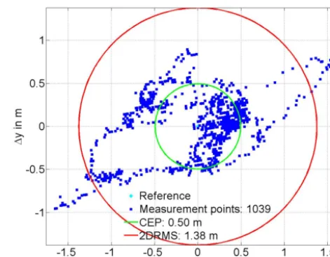
The cold-start time of 41 s met the transponder require-ments. Figure 5 shows the recorded positions of the reader against the mean circular error probability (CEP) within 50 % of the measured points are lying. With a CEP of 0.5 m, and a twice distance root mean square (2DRMS) in which 95 % of the points were within 1.38 m, the precision of the reader-side module was relatively high.
Figure 6 shows the same information but for the transponder-side GPS. With a CEP of 0.41 m and a 2DRMS of 1.68 m, the precision was comparable to that of the reader-side module. The coarser grid used on the transponder-reader-side reflected the poorer horizontal resolution provided by the Origin module of the transponder, compared to the Maestro module used in the vehicular system.
Figure 5.Recorded positions at the reader.
Figure 6.Recorded positions at the transponder.
Figure 7.Interface provided to the driver of the mowing machine. The red circle and dot on the map denote the machine position, with the blue line pointing in the direction of movement. The magenta line points towards the fawn’s location, represented by the yellow dots. The compass shows the relative direction to the fawn with relation to the movement trajectory.
Figure 8.Evaluation of the angle and distance deviation over time.
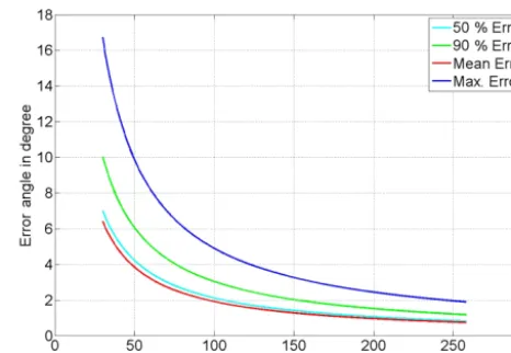
Finally, the worst case estimation of the angular error as a function of the distance was made. The calculated errors were compared with regard to the number of points in the un-derlying measurement series. The maximum error was based on the single coordinate pair with the largest angular error. The 50 and 90 % errors are with regard to the maximum er-ror observing the worst measured angle, taking account of the best fitting 50 or 90 % of the coordinate pairs. All coordi-nate sets were used in the calculation of the mean error. The extrapolated distance dependent angular errors are shown in Fig. 9.
As the distance between the reader and the transponder became shorter, the results became increasingly inaccurate. That could create problems when approaching the fawn dur-ing the recovery process. A possible solution would be to combine the GPS based localization used over longer dis-tances with a small handheld single point locator based on the conventional direction-of-arrival technique presented in (Eberhardt et al., 2015a). This would supplement the pre-sented GPS based localization over the last few meters, im-proving the success rate and speed of retrieval.
Figure 9.Relative angle error as function of distance due to GPS localization precision.
5 Conclusions
References
Ascher, A., Eberhardt, M., Lehner, M., Lippert, B., and Biebl, E.: A small UHF-RFID transponder with integrated GPS for local-ization applications, International EURASIP Workshop on RFID Technology (EURFID), Rosenheim, Germany, 22–23 October 2015, 132–139, 2015.
Eberhardt, M., Ascher, A., Lehner, M., and Biebl, E.: Array Man-ifold Manipulation for Short Distance DOA Estimation with a Handheld Device, IEEE European Conference on Smart Objects, Systems and Technologies (SmartSysTech), Aachen, Germany, 16–17 June 2015, 1–7, 2015a.
Jones, R. S.: The C Programmers Companion, 1st Edn., Silicon Press, New York, USA, 151 pp., 1991.
Misra, P. and Enge, P.: Global Positioning System. Signals, Mea-surements, and Performance, 2nd Edn., Ganga-Jamuna Press, New York, USA, 590 pp., 2006.
Rieck, W.: Die Setzzeit bei Reh-, Rot- und Damwild in Mitteleu-ropa, Zeitschrift für Jagdwissenschaft, 1, 69–75, 1955.
Sinnott, R. W.: Virtues of the Haversine, Sky and Telescope, 68, p. 159, 1984.
TI, T. I.: CC1110Fx/CC1111Fx Low-Power SoC (System-on-Chip) with MCU, Memory, Sub-1 GHz RF Transceiver, and USB Con-troller data sheet, 2013.