R E S E A R C H
Open Access
Absolute surface metrology by shear
rotation with position error correction
Weibo Wang
1,2*, Biwei Wu
1, Pengfei Liu
1, Dong Huo
1and Jiubin Tan
1Abstract
Background:Absolute test is one of the most important and efficient techniques to saperate the reference surface which usually limits the accuracy of test results.
Method:For the position error correction in absolute interferometry tests based on rotational and translational shears, the estimation algorithm adopts least-squares technique to eliminate azimuthal errors caused by rotation inaccuracy and the errors of angular orders are compensated with the help of Zernike polynomials fitting by an additional rotation measurement with a suitable selection of rotation angles.
Results:Experimental results show that the corrected results with azimuthal errors are very close to those with no errors, compared to the results before correction.
Conclusions:It can be seen clearly that the testing errors caused by rotation inaccuracy and alignment errors of the measurements can be consequently eliminated from the differences in measurement results by the proposed method.
Keywords:Absolute test, Shear rotation, Error correction, Zernike polynomials
Background
In optical interferometric testing, the test surface map is not obtained independently but only in combination with the reference surface. Several ingenious techniques have been devised to obtain absolute surface measurements, e.g., two-sphere [1, 2] method for spherical reference surfaces and“three-flat”approach for flat surface [3]. However, the classic two-sphere method with cat’s-eye position measure-ment is sensitive to the lateral shear of the coma wavefront, which will introduce astigmatism and spherical terms [2]. For decades, the shift-rotation methods without the testing of cat’s-eye position have been developed to test spherical and flat surfaces [4–9]. These approaches yield an estimate for the test surface errors without changing experimental settings, such as cavity length, that may affect the apparent reference errors. The classic multi-angle averaging method proposed by Evans and Kestner, measures the spherical sur-face atNangular positions equally spaced with respect to the optical axis and the resulting wavefronts are averaged,
then errors in the rotated member with angular orders that are not integer multiples of the number of positions will be removed without Zernike fitting [10, 11].
It always assumes that there is no azimuthal position error during part rotation in the previous absolute test methods. However, the rotations of the test part introduce uncertain-ties related to azimuthal errors of the rotational angle and lateral displacement of the part with respect to the optical axis of the interferometer [11]. Moreover, rotation should be very precise when higher order spatial frequency terms are required, which are particularly sensitive to azimuthal position errors. In practice, there are challenges to rotate the test surface accurately to the desired positions, especially for large optics, and keep the environment and metrology system stable during the multi-measurements [12]. So we present a method to determine the true azimuthal positions of part rotation and consequently eliminate testing errors caused by rotation inaccuracy.
Method
The shearing test is based on the analysis of differ-ences in measurement results that occur when rotat-ing or translatrotat-ing the test surface. The test results
* Correspondence:[email protected]
1Institute of Ultra-precision Optoelectronic Instrument Engineering, Harbin
Institute of Technology, Harbin 150001, China
2Department of Engineering Science, University of Oxford, Parks Road,
Oxford OX1 3PJ, UK
yield a collection of error maps. Each error map de-scribes the sum of apparent reference errors and test surface errors for a particular position and orientation of the test surface. If the test part is rotated to N equally spaced positions about the optical axis and the resulting, we can get the averaged wavefront
Taveðρ;θÞ ¼N1 X N−1
i¼0
Tiðρ;θÞ
¼ 1 N
X N−1
i¼0
Rðρ;θÞ þSðρ;θÞ
½ ð1Þ
whereR(ρ,θ) is the systematic error including the refer-ence surface,S(ρ,θ) is the surface error of the test part.
The wavefront of circular cross section can be ex-panded by polar coordinate polynomials in the following form
Wðρ;θÞ ¼X
k;l
Rk
lð Þρ αkl coskθþα−lksinkθ
ð2Þ
whereRklð Þρ are the radial terms of Zernike polynomials and coefficients αlk specify the magnitude of each term while the angular terms specify the angular part of the polynomial representation. ρ and θ are the normalized radial and angular coordinates.
From Eq. (2), if the wavefront is rotated to N equally spaced positions about the optical axis (φ= 2π/N), the averaged resulting wavefront can be written as
Waveðρ;θÞ ¼N1
XN−1
j¼0
W ρ;θþj2Nπ
¼ 1 N
XN−1
j;k;l Rk
lð Þρ coskθ
X
N−1
j¼0
αjlφ;kþsinkθ
X
N−1
j¼0 αjlφ;−k
! ð3Þ
where
αφ;l k αφ;l −k
" #
¼ ‐coskφ sinkφ sinkφ coskφ
αk l α−k
l
ð4Þ
For k= 0 (i.e., for rotationally symmetric terms), it is the intuitively obvious result that the procedure has no influence on rotationally symmetric terms. Fork≠0, the series sum to zero for all coskφexceptk=cN(i= 1,2,3….) and for all sinkφ. It is easy to see that rotating a wave-front to N equally spaced positions and averaging removes nonrotationally symmetric terms of all angular orders exceptkNθ. The termWkNθ(ρ,θ) is theNth rota-tionally symmetric component (angular orders kNθ), which can be written as
WkNθðρ;θÞ ¼ X
k;l −1
ð Þk Nð þ1ÞRkN
l ð Þðρ αkNl coskNθ
þα−kN
l sinkNθÞ ð5Þ
So the averaged test wavefront can be rewritten as
Taveðρ;θÞ ¼Rðρ;θÞ þSsymðρ;θÞ þWkNθðρ;θÞ ð6Þ
whereSsym(ρ,θ) is the rotational symmetry surface devi-ation of the test partS(ρ,θ).
Furthermore, the asymmetric component of the test surface can be derived as
Sasyðρ;θÞ ¼Tiðρ;θÞ−Taveðρ;θÞ þWkNθðρ;θÞ ð7Þ
The errors of angular variation kNθ can be repre-sented based on Zernike polynomials and additional shear rotation measurement [9]. And it may be always neglected in the multi-angle averaging method, when N is large enough.
Additional measurements provide redundancies to improve and characterize measurement uncertainties. However, the rotation of the test part also introduces uncertainties related to azimuthal errors of the rota-tional angle and lateral displacement of the part with respect to the optical axis of the interferometer. The effect of uncertainties will arise from uncertainties in the rotational angle. Moreover, there are challenges to rotate the test surface accurately to the desired posi-tions, especially for large optics, and keep the envir-onment and metrology system stable during the multi-measurements.
So the estimation algorithm should be presentd to eliminate azimuthal errors caused by rotation inaccur-acy. And the unknown relative alignment of the mea-surements also can be estimated through the differences in measurement results at overlapping areas.
The differenceWbetween the shear rotation measure-ments can be written as
W ¼Rðρ;θÞ þSiðρ;θÞ−Rðρ;θÞ−Sjðρ;θþφÞ ¼Siðρ;θÞ−Sjðρ;θþφÞ
¼X
k;l
Rk
lð Þρ ΔαklcoskθþΔα−lksinkθ
ð8Þ
whereΔαlk is the differences of the coefficients between two measurements.
It is trivially obvious to find αlk in terms of Δαlk from the difference of two measurements from Eqs. (4) and (8)
αk l ¼−
1 2 Δα
k l Δα
∓k l sinkφ 1−coskφ
ð Þ
ð9Þ
difference between the original wavefront and itself after rotation byφ. So the wavefront can be represented based on Zernike polynomials. Futermore, the kNθ variations of surface deviation WkNθ(ρ,θ) neglected in the multi-angle averaging method can also be obtained by add-itional rotation testing with a suitable selection of rotation angles θ0with k = cN and kθ0≠2mπ (m is an
integer).
The differences of the coefficients between two mea-surements can be written as
Δαk
l ¼αlkðcoskφi−1Þ αl∓ksinkφi ð10Þ
For azimuthal position error correction, the angle φi can be treated as additional unknowns together with the coefficients αlk. Then their actual values can be deter-mined from the measured difference wavefront by least-squares method. Then the estimation algorithm adopts least-squares technique to eliminate azimuthal errors caused by rotation inaccuracy.
From Eq. (8), the wavefront difference can be further written as
Wk i ¼
X
k;l
Rk
lð Þfρ ðcoskφi−1Þ αklcoskθþα−lksinkθ
þsinkφiα−lkcoskθþαklsinkθg ¼X
k;l
fγk
0lZklðρ;θÞðcoskφi−1Þ
þ~γk
0lZklðρ;θÞsinkφig ¼ X
k;l ξk
liZklðρ;θÞ
ð11Þ
The cost functions can be obtained by least squares method and be minimized to determine the true values of the unknowns of γk0l, ~γk0l and φi, as
dis-cussed in [12].
X N−1
i¼0
cosðkφiÞ−1
½ 2
X N−1
i¼0
sinðkφiÞ½cosðkφiÞ−1 XN−1
i¼0
sinðkφiÞ½cosðkφiÞ−1
X N−1
i¼0
sin2ðkφiÞ 2 6 6 6 6 6 4 3 7 7 7 7 7 5
γ0kl ~
γ0kl
" #
¼ XN−1 i¼0
^
Xkli½cosðkφiÞ−1X
N−1
i¼0
^ XklisinðkφiÞ
" #
ð12Þ
X
L kð Þ
l γ k
0l
2 XL kð Þ
l γ0l k ~
γk0l
XL kð Þ
l γk
0l ~γ0kl
XL kð Þ
l ~ γk 0l 2 2 6 6 6 6 6 4 3 7 7 7 7 7 5
cosðkφiÞ sinðkφiÞ
¼ XL kð Þ
l
^
Xkliγk0lþ γk0l
2
n o
X
L kð Þ
l
^
Xkli^γk0lþγk0l^γk0l
n o 2 6 6 6 6 6 4 3 7 7 7 7 7 5
ð13Þ
This generalized algorithm adopts least-squares technique to determine the true azimuthal positions of part rotation and consequently eliminates testing
errors caused by rotation inaccuracy. The true values of the unknowns of γk0l, γ~k0l and φi can be obtained
by the iterative procedure. The total computational time is influenced by the number of terms of Zernike polynomials in consideration (maximum l and k), the number of rotation N, and the precision of the initial guess of φi. Finally, the testing errors caused by
rota-tion inaccuracy can be compensated by the solurota-tions of γk0l, γ~k0l and φi.
Results
For the verification of the described method, experi-ments are presented in a standard Fizeau interferom-eter. The surface under test is a spherical mirror with a clear aperture of 100 mm and surface error within λ/10PV. The accuracy of rotations can be bet-ter than 0.1° and the 5-Axis Mount of ZYGO Com-pany can provide 13 mm X and Y adjustment, 50 mm Z adjustment and ±2° tip and tilt adjust-ment. The spherical surface is tested at the normal testing position and various orientations with the classic multi-angle averaging method. These ap-proaches can yield an estimate for the test surface errors without changing experimental settings, such as cavity length, that may affect the apparent refer-ence errors.
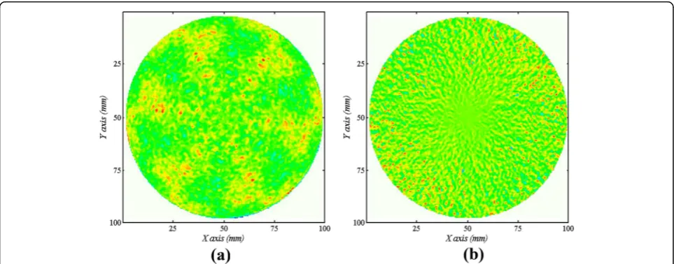
The averaged wavefronts for N= 6 and 12 are shown in Fig. 1. The errors of angular orders kNθ re-sembling a hexagon can be seen obviously from Fig. 1a, which may introduce unnecessary measure-ment errors when it is neglected in the absolute sur-face metrology. When N is large enough, the terms 2nπ/φ are close to rotationally symmetric deviations, as shown in Fig. 1b. The errors of angular orders kNθ can be quite small.
Furthermore, the averaged wavefront for N= 6 with position errors (azimuthal errors and alignment error) introduced is shown in Fig. 4 and the difference of the averaged wavefront for N= 6 before and after pos-ition errors introduced is shown in Fig. 5. Figures 1a and 4 have a similar distribution on optical path dif-ference and some difdif-ferences on PV and RMS. More details can be seen from Fig. 5. The test results are suffering from the position errors. As mentioned above, it’s difficult to rotate the test surface accurately to the desired positions, especially for large optics. There are also many challenges to keep the environment and metrology system stable during the multi-averaging
measurements, especially for largeN. So the position error correction is necessary.
Discussion
In order to correct the errors due to the rotation in-accuracy, the estimation algorithm adopts least-squares technique to determine the true azimuthal positions of part rotation and consequently eliminates testing errors caused by rotation inaccuracy. The surface is tested on the precision rotation stage with accurate position and random azimuthal errors within ±2° respectively.
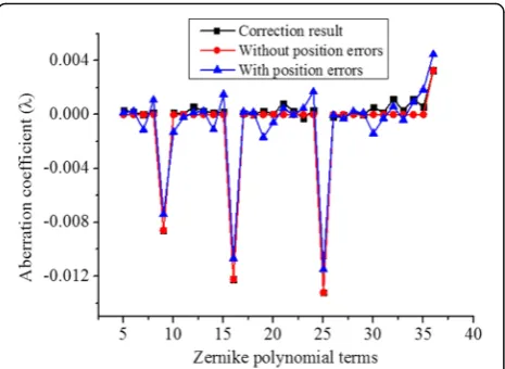
The Zernike coefficients of the results in absolute surface metrology are shown in Fig. 6. The Zernike coefficients with
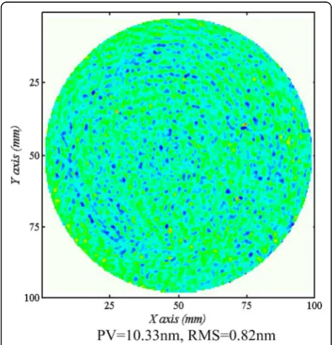
Fig. 2Differences of the averaged wavefront betweenN= 6 andN= 12 before and after compensation.aBefore compensation, PV=8.27nm, RMS=0.80nmbAfter compensation, PV=6.30nm, RMS=0.70nm
the correction of azimuthal errors and alignment errors are also shown in Fig. 6. The corrected Zernike coefficients are very close to those with fine adjustment and no additional azimuthal errors, compared to the results before correction. The coma terms (Z7 ~ Z8, Z14 ~ Z15, Z23 ~ Z24) and spherical terms (Z9, Z16, Z25, Z36) introduced by the azi-muthal errors and alignment errors have been well sup-pressed. It implies that the testing errors caused by rotation inaccuracy and alignment errors of the measurements can
be consequently eliminated from the differences in measure-ment results by the proposed method.
Conclusions
We discussed the position error estimation algorithm to determine the true azimuthal positions of part rotation and thekNθcompensation method to offer possibility to obtain high accuracy even with fewer rotation
Fig. 4The averaged wavefront forN= 6 with position errors
Fig. 5The difference of the averaged wavefront forN= 6 before and after position errors introduced
measurements. It can be used to overcome the chal-lenges of rotating the test surface accurately to the de-sired positions, especially for large optics and obtain the higher order spatial frequency terms required. Experi-mental results have been given to verify the effectiveness of the proposed method.
Funding
National Natural Science Foundation of China (51205089, 51275121 and 51475111), China Postdoctoral science foundation (2012 M520726), National Key Scientific Instrument and Equipment Development Project (2011YQ040087), China Scholarship Council (201406125121).
Authors’contributions
All authors have participated in the method discussion and result analysis. The experiments are conducted by JT. All authors have read and agreed with the contents of the final manuscript.
Competing interests
The authors declare that they have no competing interests.
Received: 29 September 2016 Accepted: 20 December 2016
References
1. Jensen, A.E.: Absolute calibration method for Twyman-Green wavefront testing interferometers. J. Opt. Soc. Am.63, 1313A (1973)
2. Selberg, L.A.: Absolute testing of spherical surfaces. In: Optical Fabrication and Testing, Vol. 13 of OSA 1994 Technical Digest Series, pp. 181–184. Optical Society of America, Washington, D.C (1994)
3. Fritz, B.S.: Absolute calibration of an optical flat. Opt. Eng. 23, 379–383 (1984)
4. Freischlad, K.R.: Absolute interferometric testing based on reconstruction of rotational shear. Appl. Opt.40(10), 1637–1648 (2001)
5. Bloemhof, E.E.: Absolute surface metrology by differencing spatially shifted maps from a phase-shifting interferometer. Opt. Lett.
35(14), 2346–2348 (2010)
6. Soons, J.A., Griesmann, U.: Absolute interferometric tests of spherical surfaces based on rotational and translational shears. Proc. SPIE8493, 84930G (2012)
7. Su, D., Miao, E., Sui, Y., Yang, H.: Absolute surface figure testing by shift-rotation method using Zernike polynomials. Opt. Lett.37, 3198–3200 (2012) 8. Weibo, W., Mengqian, Z., Siwen, Y., Zhigang, F., Jiubin, T.: Absolute spherical surface metrology by differencing rotation maps. Appl. Opt.54(20), 6186– 6189 (2015)
9. Weibo, W., Pengfei, L., Yaolong, X., Jiubin, T., Jian, L.: Error correction for rotationally asymmetric surface deviation testing based on rotational shears. Appl. Opt.55(26), 7428–7433 (2016)
10. Song, W., Wu, F., Hou, X.: Method to test rotationally asymmetric surface deviation with high accuracy. Appl. Opt.51, 5567–5572 (2012) 11. Evans, C.J., Kestner, R.N.: Test optics error removal. Appl. Opt.35(7),
1015–1021 (1996)
12. Hyug-Gyo, R., Yun-Woo, L.: Azimuthal position error correction algorithm for absolute test of large optical surfaces. Opt. Express14(20), 9169–9177 (2006)
Submit your manuscript to a
journal and benefi t from:
7Convenient online submission 7Rigorous peer review
7Immediate publication on acceptance 7Open access: articles freely available online 7High visibility within the fi eld
7Retaining the copyright to your article