APPLICATION OF ABSTRACT DATA TYPE IN DYNAMIC
PLA APPROACH
Henrikas Pranevi
č
ius, Agn
ė
Paulauskait
ė
-Tarasevi
č
ien
ė
, Dalius Makackas
Department of Business Informatics, Kaunas University of TechnologyStudentu 56-301, LT-51424 Kaunas, Lithuania e-mail: [email protected]
Abstract. This paper presents the definition of abstract data type (ADT) in dynamic Piece-Linear Aggregate (PLA) model. The introduced ADT permits to describe structural changes in the hierarchical dynamic PLA (dynPLA). In order to formalize the specification of abstract data type, the Z language is used. The application of ADT in specification of dynPLA is demonstrated by an example - the transaction processing system.
Keywords: dynamic systems, formal specification, piece-linear aggregate, abstract data types.
1. Introduction
Recently, there is a need to specify systems, which interact in the dynamic environment and react to va-rious influences by changing the type and the number of their attributes.Such systems are of variable (dyna-mic) structure, where not only the state but the structure as well is changing in time.
In the real-world applications, there are a lot of activity models, where the tasks related with structural changes are solved. In the biological field, the comp-lex evolution problems are modeled quite often, where dynamic structure is a key feature of such processes [10]. In the simulation of real biological systems a more flexible and understandable description manner is preferable. Such systems usually compose a struc-ture of few levels that leads to the dynamic hierarchi-cal modeling. Multi-agent systems (MAS) are relati-vely a new research trend, but more and more researches are performed, where agents are used to solve different problems [2]. Specific features of MAS require for various structural changes, such as migra-tion of agents, self-modificamigra-tion and others [4, 5, 6]. There are also other types of systems, which require to support changes of structure, e.g. traffic management, WEB protocols, complex networks [3].
Since such systems usually are of large scale and complex, a motivation for a formal specification occurs. Most of the formal methods can specify only the systems whose structure doesn’t vary in time. However, a task of formalization of variable structures is considered in this area as well. For the formali-zation of dynamic structures, these formalisms need to be extended. There are several formal dynamic approaches, which are based on widely used formal
method DEVS (Discrete Event Systems Specification) [16]. In dynDEVS, models are interpreted as a set of different models (incarnations) that are generating themselves by model transition functions [11, 13]. In Multi-level DEVS, apart from variable structures and dynamic ports, multi-level abstraction is provided [14].
Dynamic structure systems are also modeled with various Petri Nets (e.g. dynamic Petri Nets, Colored Petri Nets, high level Petri Nets). For example, the idea of high-level Petri nets is that model can modify its structure by adding/removing places and transitions [15].
The rest of the paper is organized as follows. In Section 2 PLA model is presented including defini-tions of classical and dynamic approaches. Section 3 provides Z specification of abstract data type for struc-tural changes in dynPLA. Section 4 illustrates an example where ADT in dynPLA specification is used. We finish with concluding remarks in Section 5.
2. Piece-linear aggregate (PLA) model
2.1. Classical PLAIn classical PLA notation, an aggregate can change only its own state, which consists of discrete and continuous components [9].
Definition 1. Aggregate A is a tuple
G H Z E E Y X
A= , , ′, ′′, , , , where
X − set of input signals; Y − set of output signals; E′− set of external events; E″− set of internal events;
…
, , 2
1
i i i
e′′ ξ ξ − controlling
sequences
ν
ν z
Z= , - the state of aggregate; v – discrete component; zv – continuous component;
H − transition operator
(H:E′∪E′′×Z→Z );
G − output operator (G:E′∪E′′×Z→Y). The schema of aggregate A is depicted in Figure 1.
Aggregate
x1
x2
xn
y1
y2
yn
Figure 1.An aggregate
Definition 2. The system of aggregates is a tupleAS = {A1,A2,..An},R , where
− Ai is an aggregate, Ai = Xi,Yi,Ei′,Ei′′,Zi,Hi,Gi
n i=1, ;
−R is the set of links between aggregates of the system
} ,... { } ,.. { } ,.. { } ,..
{A1 An Y1 Yn A1 An X1 Xn
R= × → ×
The system of aggregates is illustrated in Figure 2. Usually complex systems are described using a hierarchical approach thereby presenting them as a multi-level structure. Hierarchical structure facilitates the description of tasks which require for the layout of objects in the different levels. To define the hierarchy of aggregates, each aggregate is enabled to have a set of internal aggregates, which in turn can have the connections with their parent aggregate (“surroun-ding” aggregate) and with each other. All internal aggregates can have a set of aggregates as well. This principle is illustrated in Figure 3. Thus, the structure of hierarchical aggregate consists not only of all
attributes of classical PLA (Definition 1) but also includes other connected aggregates (Definition 2), which have the same structure as hierarchical aggre-gate.
Aggregate 1
Aggregate 2 Aggregate N
Figure 2. The system of aggregates
Definition 3. Hierarchical aggregate Ah is a
struc-tureAh = A0,A1,..An,R0,R , where
− A0 is an aggregate, which has a structure
described in Definition 1;
− A1,...An are internal aggregates, which are contained in the aggregate A0.
− R0 =A0×Y0→{A1,..An}×{X1,..Xn}∧
0 0 1
1,.... } { ,... }
{A An × Y Yn →A ×X is the set of links between aggregate A0and internal
aggregatesA1,...An;
−R ={A1,..An}×{Y1,..Yn}→{A1,..An}×{X1,..Xn} is
set of links between internal aggregates.
Aggregate Aggregate Aggregate Aggregate
Aggregate Aggregate
Aggregate
Aggregate
Figure 3. Illustration of hierarchical aggregate
2.2. dynPLA
The purpose of this section is to adapt the hierar-chical aggregate to define the systems, whose struc-ture is varying in time. Besides, the aggregates should have a capability to change their own structure autono-mously. Each set of aggregate’s attributes can be aug-mented by new element (X
( )
tm+1 =X( )
tm ∪xnew) or be reduced by removing the existing one (X( )
tm+1 = X( )
tm \xold) at a certain time moment. The changes in the aggregate model are the reactions to the internal and external events. An aggregate can perform the structural modifications, which don’t change its interface, since the external changes of the internal aggregate are internal changes of its surrounding one.) ( ), ( ), ( ), ( ), ( ), ( ), ( ), ( ),
(t Y t E t E t Z t t H t Gt A t X
Adyn= ′ ′′ ν ν s ,
where:
) (t
X − set of input signals at time moment t; )
(t
Y − set of output signals at time moment t; )
(t
E′ − set of external events at time moment t; )
(t
E′′ − set of internal events at time moment t; )
(t
Zν − set of continuous components at time moment t; )
(t
ν − set of discrete components at time moment t; )
(t
H − set of transition operators at time moment t; )
(t
G − set of output operators at time moment t ; )
(t
AS − system of aggregates at time moment t .
In classical PLA model, Markov process, which describes the changes of the aggregate’s state z(t), includes two components zv(t), v(t). Based on
dyn-PLA, the new process is denoted below:
( )
t X( ) ( ) ( ) ( ) ( ) ( ) ( ) ( ) ( )
t Y t E t E t t Z t Ht Gt A t z = , , ′ , ′′ ,ν , ν , , , S ,which describes the state of the system at each time moment t:
( )
( )
( )
{
(
}
)
( )
⎪ ⎩ ⎪ ⎨ ⎧
= ∈ ∈ =
− −
. ,
, ,.. , ,
, , ,
0 0
2 1
1 1
t t t z
t t t t z
t t t t z t
z m
m m m
3. Usage of abstract data type in dynPLA
The main goals of the usage of ADT are: to have clear, precise and unambiguous description of com-mon data with associated operations; to encapsulate the specification; to provide the basis for their reali-zation in programs.
ADT in PLA method was used as well to solve the certain group of problems where the set of particular data with associated operations were used rather frequently in the specification. For instance, ADT of queue was used to specify protocols [9] in order to make the specification more compact and to avoid the declaration of usual operations.
In dynPLA model, four types of structural changes of the system of aggregates may occur: addition of the new link; removal of existing link, addition of the new aggregate, removal of existing aggregate. It is possible to declare the common actions for each group of structural changes described above:
1. Addition of a link: the corresponding link
(
Ai,y)
( )
Aj,x , i≠ j is added to the set of links;new output signal y is added to the set of output signals of source aggregate Ai; new input signal, ex-ternal event, transition and output operators to process the new signal are added to the corresponding sets of target aggregate Aj.
2. Removal of a link: the link is removed from the set of links; output signal is removed from the set of output signals of source aggregate; input signal,
external event, transition and output operators to pro-cess the old signal are removed from the corres-ponding sets of target aggregate.
3. Creation of an aggregate: the aggregate Ai is added to the set of aggregates.
4. Removal of an aggregate: the aggregate Ak is removed from the set of aggregates; all links associated with removed aggregate are deleted
) , ( ) , (
| A y A x R
r∈ k j
∀ or ∀r∈R|(Ai,y) (Ak,x).
It is appropriate to consider the use of data abstrac-tions for such acabstrac-tions, declaring system of aggregates as a set of data with associated operations listed above. To invoke any of these operations, the precise description of format for input information is defined. To add or remove a link, the information of type
(
Ai,y)
( )
Aj,x , i≠ j is required. To add the newag-gregate, the name and type of aggregateAk have to be referred. To remove the certain aggregateAk, only the name of the aggregate is required, since all names of aggregates are unique.
3.1. Formalization of abstract data types using Z notation
Specifications of abstract data types provide the basis for their realization. Formal specification is used to validate the statement about model description. For the formal description of ADT specification, Z nota-tion was chosen [8]. This method enables an unambi-guous description of all actions for structural changes in the system of aggregates. Restrictions and condi-tions which have to be met in order to perform struc-tural changes correctly and to avoid faults were included, e.g. we can’t create a link, which already exists. The specification of abstract data type was vali-dated using Z notation prover Z/EVES, which has possibilities to check the syntax and semantic of models or even to write theorems [12].
3.2. Z specification of abstract data type for structural changes
In Z specification language all data abstractions and operations are defined as separate components called schemas. The specification of ADT of structural changes in dynPLA is described below.
Global sets of attributes [ID,Xp,Yp,E1p,E2p,υp] are given bellow:
• ID − set of all possible names of aggregates;
• Xp − set of all possible input signals;
• Yp − set of all possible output signals;
• E1p− set of all possible external events;
• E2p− set of all possible internal events;
aggregate with its output signal Yp and the name ID of target aggregate with its input signal Xp:
(
ID Xp) (
ID Yp)
on
RInformati = × × × .
The operation for creation of new aggregate uses
the type information AgInformation as input
parameters, which includes the name and type of new aggregate:
(
ID Agg)
ion
AgInformat = × .
The state of surrounding aggregate is described using state variables of Z schema Aggregate.
The set Ag of internal aggregatesis of the structure
[
id:ID,X: Xp,Y: Yp,...]
Agg= Ρ Ρ , which has the
same structure as Z schema Aggregate.
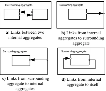
Surrounding aggregate
a) Links between two internal aggregates
Surrounding aggregate
b) Links from internal aggregates to surrounding
aggregate
Surrounding aggregate
c) Links from surrounding aggregate to internal
aggregates
Surrounding aggregate
d) Links from internal aggregate to itself
Figure 4. Allowed types of links in dynPLA
In the predicate of schema Aggregate, the different kinds of possible links are defined: 1) between two in-ternal aggregates (Figure 4a); 2) from inin-ternal aggre-gates to surrounding aggregate (Figure 4b.); 3) from
surrounding aggregate to internal aggregates (Figure 4c); 4) from internal aggregate to itself (Figure 4d.).
3.2.1. Operations
Four fundamental schemas for the structural changes of system of aggregates were developed. Add_R schema describes the creation of the new link. It has two preconditions, which define the constraints on the operation: aggregates id1, id2, which will be connected by the new link, have to belong to the set of aggregates Ag; the new link newR can’t exist in the set of links R. If it is true, the predicate of Add_R specifies that the set of links after the completion of the operation is augmented by the new link newR. In this operation, all state variables remain unchanged, except R.
Only the added link is visible for external observer. The aggregates, which have to be connected by the new link, perform structural changes in their inside structure as well. AgchangesX and AgchangesY sche-mas define the structural changes in the source and target aggregates.
In order to apply such actions only to the aggre-gates, which have to be connected by the new link, the partial operations of Aggregate schema named as the
framingschemas were used.
The first framing schema ΦFraming1 defines the changes in the source aggregate, the second one
Since the framing schema by itself does not resent any system operation, it is combined with pre-vious definitions: ΔAgg, AgchangesX or AgchangesY. Above defined framing schemas are combined in the following way:
AgchangesX Framing1
Agg
SchemaforX =∃Δ ⋅Φ ∧
AgchangesY Framing2
Agg
SchemaforY =∃Δ ⋅Φ ∧
Finally, the operation of the link creation can be defined as a composition of SchemaforX, SchemaforY and Add_R schemas:
R Add SchemaforY SchemaforX
AddR= ∧ ∧ _
The operation for removal of link is described in the same way as operation of link creation, whereas all corresponding signals (input and output), transition and/or output operators and link are not added but deleted.
AddAg schema describes the creation of new ag-gregate. The new aggregate can be added only if it doesn’t belong to the set of internal aggregates Ag.
RemoveAg schema describes the removal of the aggregate. To remove the aggregate from the system, it is not sufficient to delete the aggregate from the set of aggregates. All links associated with aggregate have to be removed as well.
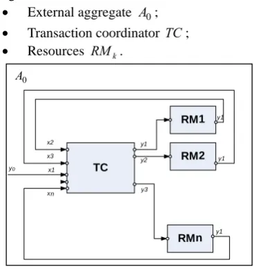
4. An example
To demonstrate the application of abstract data type in dynPLA, an example − the model of transac-tion processing system is introduced.
The transaction processing system consists of transaction coordinator (TM), which handles resources (RM), which in turn perform certain actions. When transaction coordinator receives a request to perform a task, it forwards this task to the particular resource. When resource completes the task, it notifies the trans-action coordinator, which in turn can free up the resource [7].
4.1. Specification of the transaction processing system
The transaction processing system is presented in Figure 5. The system of aggregates includes such aggregates:
• External aggregate A0;
• Transaction coordinator TC;
• Resources RMk.
TC
RM1
RMn
y3
RM2
y1 x2
x3
y2
xn x1
y1
y1
y1 0
A
y0
Figure 5. The structure of the system of aggregates
In the specification of transaction processing sys-tem given below, ADT (section 3.2) are used to describe the structural changes of the system of aggregates:
• RemoveAg− to remove the existing aggregates RMk;
• AddR− to create new links between TC and aggre-gates RMk.
Formal descriptions of all aggregates of system are presented using method of controlling sequences [9].
4.1.1. The system of aggregates
The analyzed system is presented as a set of aggregates:
( )
t{
A( ) ( )
t TC t RM} ( )
RtAs = 0 , ∪ , ,
where
:
RM
{
RM1,...RMn}
,( )
)}, , ( ) , ( ), , ( ) , ( ), , ( ) , {( 1 1 1 0 0 m k k k x TC y RM x RM y TC x TC y A t R → → → =where k=1,(#RM), m=2,(#RM+1).
Below is depicted the structure of the system of aggregates at initial time moment (Figure 6).
Figure 6. Themodel of Transaction processing system at initial time moment.
In this time moment, the system has two connected aggregates TC and A0:
( )
t0{
A0( ) ( )
t0 ,TCt0} ( )
,Rt0As = ,
where R
( ) (
t0 = A0,y0) (
→ TC,x1)
.4.1.2 A0aggregate
Aggregate A0 is responsible for generation of the new tasks, which are transmitted to the transaction coordinator TC.
1.X =∅. 2.Y ={y0}. 3.E'=∅.
4.E"={e"1}− the generation of the new tasks.
{e"1}→{ϕk(1)}, k=1,∞, where ϕk(1) − the time
period between generation of k-th and (k-1)th tasks. 5 ν
( )
t =∅.6 zν
( )
t =w(e"1,tm), zν( )
t0 =∞ 7.H={
H( )
e1′′}
.8.G=
{
G( )
e1′′}
. : ) " (e1H // the end of generation of the new task//
1 1, 1)
"
(e tm tm i
w + = +η , .
: ) "
(e1 y0 task
G =
4.1.3. TCaggregate
TC is a transaction coordinator, which receives re-quests from external aggregate A0 and performs the tasks. All received requests are inserted into the FIFO queue. It forwards each request to the corresponding resource aggregates. When a resource completes the task, it notifies the TC aggregate, which in turn release the resource.
1.X
( )
t ={x1,x2,...xcnt(t)+1}.2.Y
( )
t ={y1,y2,...ycnt(t)}.3.E'
( )
t ={e'1,e′2,...e'cnt(t)+1}.4.E"={e1′′}, where e1′′– is processing of the task Set E” is not varying in time.
∞ = →{ }, 1, }
"
{e1 ηk(1) k , where
) 1 (
k
η − the time period between processing of k-th and (k-1)th tasks. 5.ν
( )
t ={
AS( ) ( )
t,Qt,cnt(t)}
,where Q
( )
t – a queue of tasks;.( )
tAS – a set of aggregates of system; )
(t
cnt – the number of active resources. 6.zν
( )
t ={w(
e1′′,tm)
}.7.H
( )
t ={
H( ) ( )
e1′,H e2′ ,...H(
ecnt′ (t)+1)
}
.8.G
( )
t ={
G( ) ( )
e1′,Ge′2 ,G(
e′cnt(t)+1)
}
.Descriptions of transition and output operator, which define the changes of RA aggregate’s coordinates are presented below
: ) ' (e1
H // the new task is received //
( )
(
)
(
)
(
,)
,( )
0,, , , , # 1 1 1 = + = ′′ ∞ ≠ ′′ m k m m m m t Q if t t e w t e w if task t Q ENQ η ∅ = Y e
G( '1): . :
) (e1
H ′′ // the end of processing of the task //
( )
(
)
( )
0, ). ), ( ( , 1 ) ( ) 1 ( , # ≠ ⎪ ⎭ ⎪ ⎬ ⎫ + = + m m S m m m t Q if CA t A AddAg t cnt t cnt t Q DEQwhere CA=RMcnt(tm+1),
) ), (
(A t CR
AddR S m ,
where CR ={(RMcnt(tm+1),y1)→(TC,xcnt(tm+1)+1),
(TC,ycnt(tm+1))→(RMcnt(tm+1),x1),
(
e1′′,tm)
=tm+ 1k, if #Q( )
tm =0,w η
, : ) (e1 y1h
G ′′ where h=cnt
(
tm+1)
. :) ' (ek
H // the forwarded task is accomplished // )
), (
(A t DA
RemoveAg S m , where DA=RMk,
where k=2,cnt(t)+1,
∅ =
Y e
G( 'k): .
The structure of aggregate TC at the initial time moment is described below:
2.Y
( )
t0 =∅, 3.E'( )
t0 ={e'1}, 4.E"={e1′′},5.ν
( )
t0 ={
AS( ) ( )
t0 ,Qt0 ,cnt(t0)}
, where Q( )
t0 =0,0 ) (t0 =
cnt ,
the structure of AS
( )
t0 at initial time moment is defi-ned in section 4.1.1.6.zν
( )
t0 ={∞}, 7.H( )
t0 ={
H( )
e1′}
, 8.G( )
t0 ={
G( )
e1′}
.4.1.4. RMkaggregate
The aggregate RMk receives a task from transac-tion coordinator TC. During the internal event, the re-ceived task is performed. Whenever the task is accom-plished, the resource aggregate RMk informs trans-action coordinator TC by generating the output signal. 1.X ={x1}.
2.Y={y1}. 3.E'={e1′}.
4.E"={e"1}−the performance of received task.
{e"1}→{ϕ1(1)} − the processing duration of the task. 5 ν
( )
t =∅.6 zν
( )
t =w(e"1,tm), zν( )
t0 =∞ 7.H={
H( ) ( )
e1′,H e1′′}
.8.G=
{
G( ) ( )
e1′,Ge1′′}
. :) ' (e1
H // the forwarded task is received //
w(e"1,tm+1)=tm+ϕi
1 1): '
(e Y =∅
G .
: ) " (e1
H // the performance of received task // w(e"1,tm+1)=∞
1 1):
(e Y y
G ′′ = .
In this example, the structures of aggregates RMk and A0 are not varying in time. System of aggregates is used as abstract data type. Defined operations (section 3.2.1) in advance were enough to perform all structural changes in analyzed system.
5. Concluding remarks
In this paper we demonstrated the usage of abstract data type (ADT) for structural changes in the dynamic PLA model. For the formalization of ADT, Z speci-fication language has been chosen, since it provided a complementary representation of the dynamic behavior of aggregates. Besides, Z notation allowed us to define ADT in mathematically rigorous manner based on the set theory and predicate calculus. Introduced ADT has been verificated using Z/EVES prover. It permits to check the syntax and the semantic of specification, ensuring that ADT was defined correctly. In dynPLA,
the application of predefined ADT allowed us to get the compact specification for considered example.
In the future, this approach will be used for formali-zation of the Session Invitation Protocol (SIP).
References
[1] F. J. Barros. Modeling formalisms for dynamic struc-ture systems. ACM Trans. Model. Comput. Simul. Vol.7, No. 4, 1997, 501–515.
[2] F. Bellifemine, G. Claire, D. Greenwood. Developing Multi-Agent Systems with JADE. John Wiley & Sons. Ltd., 2007.
[3] S. Boccaletti, V. Latora, Y. Moreno, M. Chavez,
D.-U. Hwang. Complex networks: Structure and dynamics. Physics Reports, Vol.424, No. 4-5, 2006, 175–308. [4] F. M. T. Brazier, N. J. E. Wijngaards. Designing
Self-Modifying Agents. Proceedings of Computational and Cognitive Models of Creative Design, the fifth international roundtable conference Computing, Uni-versity of Sydney, 2001, 93-112.
[5] F. M. T. Brazier, B. J. Overeinder, M. van Steen,
N. J. E. Wijngaards. Generative Migration of Agents. Proceedings of the AISB’02 Symposium on Adaptive Agents and Multi-Agent Systems, 2002, 116-119. [6] V. Dignum, F. Dignum, L. Sonenberg. Towards
dyna-mic organization of agent societies. Workshop on Coor-dination in Emergent Agent Societies, 2004, 70–78. [7] Š. Packevičius, A. Kazla, H. Pranevičius. Extension of
PLA Specification for Dynamic System Formalization. Information Technology And Control, 2006, Vol.35, No.3, 235 – 242.
[8] B. Potter, J. Sinclair, D. Till . An Introduction to For-mal Specification and Z. Prentice Hall, Trowbridge, UK, 1996.
[9] H. Pranevičius. Formal Specification and Analysis of Computer Network Protocols: Aggregate Approach. Technologija, Kaunas, 2004 (in Lithuanian).
[10] J. R. Prill, P.A. Iglesias, A. Levchenko. Dynamic Properties of Network Motifs Contribute to Biological Network Organization. 2005, PloS Biology, Vol. 3(11), 650 – 659.
[11] M. Rohl,A. M. Uhrmacher. Controlled Experimen-ta-tion with Agents - Models and ImplementaExperimen-ta-tions. 5th International Workshop. “Engineering Societies in the Agents World”, Toulouse, France, 2004, October, 20-22, 292-304.
[12] M. Saaltink. The Z/EVES 2.0 User‘s Guide. TR – 99-5493-06a, ORA Canada, Canada, 1999.
[13] A. M. Uhrmacher. Dynamic Structures in Modeling and Simulation : A Reflective Approach. ACM Transactions on Modeling and Computer Simulation, Vol.11, No.2, 2001, 206-232.
[14] A. M. Uhrmacher, R. Ewald, M. John, C. Maus, M.
Jeschke, S. Biermann. Combining Micro and macro-modeling in DEVS for computational biology. Proceedings of the 2007 Winter Simulation Conference, IEEE Press, 2007, 871-880.
[15] D. Xu, Y. Deng. Modeling mobile agent systems with high level Petri nets. Proc. IEEE International Conference on Systems, Man and Cybernetics (SMC’2000), Vol.5, 2000, 3177-3182.
[16] B. P.Zeigler, H. Praehofer, T. G. Kim. Theory of Mo-deling and Simulation. Second Edition, Academic Press, 2000.