Author for correspondence:
1Student, Department of Mechanical, Tirumala Engineering College, Bogaram, Keesara, RangaReddy, Telangana,
Volume-5 Issue-2
International Journal of Intellectual Advancements
and Research in Engineering Computations
A sensor controlled braking system
Shashi Kumar Sour
1, Md Ramiz Akhtar
1, Ashish Kumar
1, Kumar Abhishek Ranjan
1,
Avinash Kumar Sinha
1Guides: G.Phaneendra Kumar, B.Naresh
ABSTRACT
This project presents “A sensors controlled braking system”. Driving is a compulsory activity for most of the people. People use their automobile to move from one place to another. The number of vehicle is increasing day by day. So, road accidents are a common problem in today’s scenario. Numbers of Accidents occurs everyday and causes worst damage, serious injury and death. These accidents are mostly caused due to loss of control, drunk and driving, rash driving etc.
Our project is designed to develop a new system that can solve this problem where drivers may not apply brake manually but the vehicles can stop automatically by sensing the obstacles in front of it. This project is about a system that can control braking arrangement for safety of vehicle and driver. This braking arrangement is controlled by the system which consists of control unit with solenoid valve ,this system get activated when it receives ultrasonic wave signal from ultrasonic sensors, after detecting object in front of vehicle within a predetermined distance. This project demonstrates the possible use of an automatic braking mechanism in this system.
Thus it provides an advance safety braking arrangement without applying manual brake
INTRODUCTION
Our project is presented to “A sensor
controlled braking system”
This system consists of ultrasonic sensors namely ultrasonic wave emitter and ultrasonic wave receiver. The ultrasonic wave emitter is provided in front portion of the car, producing and emitting ultrasonic waves in a predetermined distance in front of the car, this emitted waves reflected back and received by the ultrasonic receiver after detecting the object in front of it. The reflected wave (detection pulse) is measured to get the distance between vehicle and the obstacle, the resulting system can achieve measurement with high accuracy and improve short distance also .After the receiver receives the signal , it sends the controlled signal to the control unit, after processing the signal in microcontroller it sends the electrical signal to solenoid valve which is connected with compressor which releases
compressed air to double acting pneumatic cylinder and thus it apply its energy to braking arrangement mechanism to apply brake. Theoretically, a vehicle equipped with modern braking technology and adaptive control is equipped with all of the necessary hardware to allow a simple collision avoidance system that would be capable of detecting when a collision is likely to occur and applying emergency braking to avoid it.
Using ultrasonic as a ranging sensor, which works based on ultrasonic wave. The main target for this project is, automobile can automatically apply brake when the sensor senses the obstacles. The braking circuit function is to brake the car automatically after receiving the signal from the sensors.
Need for automatic braking system
When a safety factor of a vehicle is considered a primary factor that flashes in mind is its brakes or braking system .So a braking system is such a vital
Copyrights © International Journal of Intellectual Advancements and Research in Engineering Computations, component that is necessarily required when a
vehicle is considered. It reduces the kinetic energy of the vehicle in conditions when a vehicle has to slow down or also it has to be stopped. Thus making sure the vehicle and the passengers inside it are safe. Thus a braking system is always needed to ensure the safety of the drivers and passengers uncountable valued lives.
Survey
1, 46, 133 people died in India due to road accident in 2016. The total number of fatalities represent an increase of 4.6% on the previous year. 1. More than half of the people killed in more than
500,000 road accidents last year were aged 15-34. 2. Road accidents are common in India, often due to
poor driving or badly maintained roads and vehicles. Experts blame poorly designed roads. 3. A report released by India's ministry of road
transport says:
4. 146,133 people were killed in road accidents in India in 2016, up from 139,671 in 2015. 5. There were 501,423 road accidents in 2015 - or
1,374 accidents every day - up from 489,400 in 2015.
6. 500,279 people were injured in road accidents in 2015, up from 493,474 in 2015.
7. 400 road deaths take place every day on India's roads.
8. 13 states, including Tamil Nadu, Maharashtra, Madhya Pradesh, Karnataka, Kerala and Uttar Pradesh, accounted for more than 80% of all road accidents and fatalities
9. Nearly eight in ten accidents were caused by drivers, with 62% of those blamed on speeding.
Transport minister Nitin Gadkari said there is an "urgent need" to improve road infrastructure as the number of survey showed road accidents were one of the single biggest causes of death in India
Report on investigation
When we saw the number of accidents is increasing day by day we looked forward to reduce this accidents by implementing new and advance safety features in braking mechanism which will be highly efficient in reducing the number of accidents by installing this advance feature in automobile.
As during the investigation we found that the main reason for road accident is loss of control, unconscious state of mind while driving, rash driving etc.
From the above investigation we came to the conclusion that if there is an object detecting device which can detect an object to a certain distance then by adding some mechanism we can stop the vehicle.
Going through the investigation we found different type sensors, whose output with the help of microcontroller can be converted into mechanical movement by using solenoid valve.
Investigation on sensors
IR sensor
Infrared (IR) light leaving an LED reflects off an object. The reflected light travels back to an IR receiver. The IR receiver “detects” the presence of the object. The object does not need to move to be detected.
Fig: 1.1 IR sensor
This sensor provides the system with ability to detect the presence of object position. The theory is the IR emitter emits infrared light. If an object presence the signal will be reflected back to the
Copyrights © International Journal of Intellectual Advancements and Research in Engineering Computations,
Disadvantages
Although infrared sensors have many advantages, they also have several disadvantages. They are incapable of distinguishing between objects that irradiate similar thermal energy levels. Infrared detectors are also rather expensive, so they are not as widely used as they could be
Reverse parking sensor
Parking sensors are proximity sensors for road vehicles designed to alert the driver to obstacles while parking. These systems use either electromagnetic or ultrasonic sensors.
Fig: 1.2 reverse parking sensor
The Parking Sensor, originally called, Reverse Aid, was a spin-off from the Sonic Pathfinder, an Electronic Guidance Device for the Blind. Both devices were invented in the late 1970s by Tony Heyes while working at the Blind Mobility Research Unit at Nottingham University in the UK. After patenting the device in 1983 Hayes offered it to Jaguar Cars in Coventry. After test driving the prototype on Heyes's car they very politely told him that, "You like it because you are a one-eyed driver who cannot judge distances. Real people would not want a thing like this."
Tony heyes teamed up with a local manufacturer and some 150 units were made and
fitted to petrol tankers, trucks and delivery vehicles. Very few were fitted to private cars since few people wanted to drill holes in their cars.
Ultrasonic sensor
Copyrights © International Journal of Intellectual Advancements and Research in Engineering Computations,
Fig: 1.3 Ultrasonic sensor
Ultrasonic transducer
Ultrasonic transducers are divided into three broad categories: transmitters, receivers and transceivers. Transmitters convert electrical signals into ultrasound, receivers convert ultrasound into electrical signals, and transceivers can both transmit and receive ultrasound.
In a similar way to radar and sonar, ultrasonic transducers are used in systems which evaluate targets by interpreting the reflected signals. For example, by measuring the time between sending a signal and receiving an echo the distance of an object can be calculated. Passive ultrasonic sensors are basically microphones that detect ultrasonic noise that is present under certain conditions.
After going through all of these sensors we decided to proceed forward with ultrasonic sensor as it had more features than other sensor.
Advantages
Ultrasonic sensors produce ultrasonic frequencies that humans cannot hear, making them ideal for quiet environments. They do not use much electricity, are simple in design, and are relatively inexpensive. Some piezoelectric crystals transmit and receive ultrasonic sound waves. Likewise, ultrasonic sensors can be used with both radio and sound waves.
Disadvantages
Ultrasonic sensors do not have many disadvantages, but are limited in their capabilities. For example, density, consistency, and material can distort an ultrasonic sensor’s readings
Report on implementation
As the number of automobile introducing every day with latest technologies and are implemented with advanced safety features. In automobile, braking system is the most prominent safety feature of car where we can introduce different concepts with latest technique to have immediate and automatic braking system.
Presently cars have the alarm system where, when the car gets too close to an object an alarm is triggered which warns the driver about an object which is going to have a front collision. But this feature has produced lot of problems and are prone to human error so we have enhanced the facility by using the same system but we have altered it so the car automatically apply brakes when an obstacle comes in front of it . So we designed and developed
SENSORS CONTROLLED AUTOMATIC
Copyrights © International Journal of Intellectual Advancements and Research in Engineering Computations,
CHAPTER-2
BRAKES
The foot brake or service brake is always applied by a pedal, while the parking brake is applied by a hand lever. The parking brake is intended chiefly to hold the car in position. The parking brake can be set in the “ON” position by means of a latch while the service brake remains on only as long as the driver presses down on the pedal. The hand brake is normally used only after the driver has stopped the car by using the foot brake. Its other use is as an emergency brake to stop the car if the foot brake system should fail. The hand or parking brakes operates on a pair of wheels, frequently the rear wheels. When drum type rear brakes are used, the same shoes can be used for both hand and foot control.
The drum type of brake may either be a band brake or a shoe brake. Both band brakes and shoe brakes may be either external or internal. The band brakes generally are external and shoe brakes internal. In drum brakes the drum is attached to the wheel and revolves with it. Friction to slow the drum is applied from inside by the shoes which do not rotate but are mounted on a stationary metal back plate. There are different types of drum brakes such as a two leading shoe arrangement – which gives an augmented response to pedal effort because of its self applying arrangement. A leading-trailing shoe is a cheaper and better alternative as it is equally effective whether the car is going forward or backwards. Manufacturers
design drum brakes so that rain, snow or ice or grit cannot get inside and decrease braking efficiency for moisture greatly reduces the friction between the linings and the drum. The dissipate quickly the considerable amount of heat generated when braking a fast moving heavy car large brake drums would be required. Disc brakes do the job more efficiently, for the cooling air can get to the rubbing between each piston and the disc, there is a friction pad held in position by retaining pins, spring plates etc. Passages are drilled in the caliper for the fluid to enter or leave the each housing. These passages are also connected to another one for bleeding. Each cylinder contains a rubber selling ring between the cylinder and the piston.
The brakes are applied, hydraulically actuated piston move the friction pads into contact with the disc, applying equal and opposite forces on the later. On releasing the brakes, the rubber sealing rings act as return springs and retract the pistons and the friction pads away from the disc.
Hydraulic brakes (disc brake)
The hydraulic brakes are applied by the liquid pressure. The pedal force is transmitted to the brake shoe by means of a confined liquid through a system of force transmission. The force applied to the pedal is multiplied and transmitted to brake shoes by a force transmission system.
This system is based upon Pascal’s principle, which states that “The confined liquids transmit pressure without loss equally in all directions”.
Copyrights © International Journal of Intellectual Advancements and Research in Engineering Computations, It essentially consists of two main components –
master cylinder and wheel cylinder the master cylinder is connected by the wheel cylinders at each of the four wheels. The system is filled with the liquid under light pressure when the brakes are not in operation.
The liquid is known as brake fluid, and is usually a mixture of glycerin and alcohol or
caster-oil, denatured alcohol and some additives Spring pressure, and thus the fluid pressure in the entire system drops to its original low valve, which allows retracting spring on wheel brakes to pull the brake shoes out of contact with the brake drums into their original positions. This causes the wheel cylinder piston also to come back to its original inward position. Thus, the brakes are released.
CHAPTER 3
LITERATURE SURVEY
Ultrasonic sensor
Fig: 3.1 ultrasonic sensor
SUMMARY
Ultrasonic sensors are based on measuring the properties of sound waves with frequency above the human audible range. They are based on three physical principles: time of flight, the Doppler effect, and the attenuation of sound waves. Ultrasonic sensors are non-intrusive in that they do not require physical contact with their target, and can detect certain clear or shiny targets otherwise obscured to some vision-based sensors. On the other hand, their measurements are very sensitive to temperature and to the angle of the target.
Introduction
Ultrasonic sensors “are based on the measurement of the properties of acoustic waves with frequencies above the human audible range,”
often at roughly 40 kHz . They typically operate by generating a high-frequency pulse of sound, and then receiving and evaluating the properties of the echo pulse. Three different properties of the received echo pulse may be evaluated, for different sensing purposes. There are Time of flight (for sensing distance) Doppler shift (for sensing velocity) Amplitude attenuation (for sensing distance, directionality, or attenuation coefficient)
Generating the ultrasonic signal
Copyrights © International Journal of Intellectual Advancements and Research in Engineering Computations, detected by a piezoelectric receiver, which converts
the waves back into voltage using the same method. The signal may also be generated by consumer electronics products, but great care must be taken to ensure that the signal is not attenuated in this range. Speakers typically have filter circuits to prevent ultrasonic propagation, and the frequency response of many microphones roll off in this range. This is partly because of the amount of ultrasound present in our daily life; percussive sounds and metallic ringing both contain ultrasonic frequencies.
Pulsed Vs continuous signal
Time-of-flight-based sensing requires emitting a pulse and waiting for it to return. These waiting time limits the speed with which successive measurements can be made, without risking confusion. However, Doppler- and attenuation-based sensing devices do not have the same restrictions: a constant wave of ultrasound may be emitted, and the received wave's attenuation or frequency continuously analyzed. This may make measurements speedier, effectively increasing the sensitivity of the sensor.
Fig: 3.4 b Working of ultrasonic sensor
Considerations
The main advantage of ultrasonic sensors is that measurements may be made without touching or otherwise impeding the target. In addition, depending on the distance measured, measurement is relatively quick (it takes roughly 6ms for sound to travel 1m). However, many factors such as temperature, angle, and material may affect measurements.
Here is a list of pitfalls in ultrasonic sensing
Weather: Temperature and humidity affect the speed of sound in air. Therefore, range finders may need to be recalibrated to make accurate measurements in a new environment. (Or, an on-board temperature sensor may be incorporated.)
Currents: Temperature variations and air currents can create invisible boundaries that will reflect
ultrasonic waves, so care must be taken to avoid these.
Angle: For the transmitted wave to echo back to the receiver, the target surface must be perpendicular to the transmitter. Round objects are therefore most easily sensed since they always show some perpendicular face. When targeting a flat object, care must be taken to ensure that its angle with respect to the sensor does not exceed a particular range.
Copyrights © International Journal of Intellectual Advancements and Research in Engineering Computations,
Material: Some materials are more absorbent than others, and these will reflect less ultrasound. This complicates using the attenuation method to measure the distance of arbitrary objects.
Controller
The Arduino Uno is a microcontroller board based on the ATmega328. It has 14 digital
input/output pins (of which 6 can be used as PWM outputs), 6 analog inputs, a 16 MHz ceramic resonator, a USB connection, a power jack, an ICSP header, and a reset button. It contains everything needed to support the microcontroller; simply connect it to a computer with a USB cable or power it with a AC-to-DC adapter or battery to get started.
Fig.3.5 Arduino Uno microcontroller
Power
The Arduino Uno can be powered via the USB connection or with an external power supply. The power source is selected automatically.
External (non-USB) power can come either from an AC-to-DC adapter (wall-wart) or battery. The adapter can be connected by plugging a 2.1mm center-positive plug into the board's power jack. Leads from a battery can be inserted in the Gnd and Vin pin headers of the POWER connector.
The board can operate on an external supply of 6 to 20 volts. If supplied with less than 7V, however, the 5V pin may supply less than five volts and the board may be unstable. If using more than 12V, the voltage regulator may overheat and damage the board. The recommended range is 7 to 12 volts.
Memory
The ATmega328 has 32 KB (with 0.5 KB used for the bootloader). It also has 2 KB of SRAM and 1 KB of EEPROM (which can be read and written with the EEPROM library).
Input and output
Each of the 14 digital pins on the Uno can be used as an input or output, using pin Mode (), digital Write(), and digital Read() functions. They operate at 5 volts. Each pin can provide or receive a maximum of 40 mA and has an internal pull-up resistor (disconnected by default) of 20-50 kOhms. In addition, some pins have specialized functions
Programming
The Arduino Uno can be programmed with the Arduino software download. Select "Arduino Uno from the Tools > Board menu.
The ATmega16U2 (or 8U2 in the rev1 and rev2 boards) firmware source code is available. The ATmega16U2/8U2 is loaded with a DFU bootloader, which can be activated by:
On Rev1 boards: connecting the solder jumper on the back of the board and then resetting the 8U2.
On Rev2 or later boards: there is a resistor that pulling the 8U2/16U2 HWB line to ground, making it easier to put into DFU mode.
Copyrights © International Journal of Intellectual Advancements and Research in Engineering Computations,
Solenoid valve
The directional valve is one of the important parts of a pneumatic system. Commonly known as DCV, this valve is used to control the direction of air flow in the pneumatic system. The directional valve does this by changing the position of its internal movable parts. This valve was selected for speedy operation and to reduce the manual effort
and also for the modification of the machine into automatic machine by means of using a solenoid valve. A solenoid is an electrical device that converts electrical energy into straight line motion and force. These are also used to operate a mechanical operation which in turn operates the valve mechanism. Solenoids may be push type or pull type. The push type solenoid is one in which the plunger is pushed when the
Fig: 3.3 Solenoid valve
Solenoid is energized electrically. The pull type solenoid is one is which the plunger is pulled when the solenoid is energized. The name of the parts of the solenoid should be learned so that they can be recognized when called upon to make repairs, to do service work or to install them.
Air compressor
An air compressor is a device that converts power (using an electric motor, diesel or gasoline
Copyrights © International Journal of Intellectual Advancements and Research in Engineering Computations,
Fig: 3.4 Air Compressors
The energy contained in the compressed air can be used for a variety of applications, utilizing the kinetic energy of the air as it is released and the tank depressurizes. When tank pressure reaches its lower limit, the air compressor turns on again and re-pressurizes the tank.
CHAPTER 4
PNEUMATIC
AND
BRAKING
ARRANGEMENT
Double acting pneumatic cylinder
Pneumatic cylinder consist of a. PISTON
b. CYLINDER
Copyrights © International Journal of Intellectual Advancements and Research in Engineering Computations,
Fig: 4.1 Pneumatic piston
Cylinder technical data
Table 4.3.1
Piston Rod: M.S. hard Chrome plated
Seals: Nitrile (Buna – N) Elastomer
End Covers: Cast iron graded fine grained from 25mm to 300mm
Piston: -Aluminum.
Media and Temperature Range: -Air, 0°c to 85°c
BRAKING ARRANGEMENT
Disc brake
A disc brake is a type of brake that uses calipers to squeeze pairs of pads against a disc in order to create friction that retards the rotation of a shaft, such as a vehicle axle, either to reduce its rotational speed or to hold it stationary. The energy of motion is converted into waste heat which must be dispersed. Hydraulic disc
brakes are the most commonly used form of brake for motor vehicles but the principles of a disc brake are applicable to almost any rotating shaft.
Copyrights © International Journal of Intellectual Advancements and Research in Engineering Computations,
Fig: 4.2 disc brake
Most drum brake designs have at least one leading shoe, which gives a servo-effect. By contrast, a disc brake has no self-servo effect and its braking force is always proportional to the pressure placed on the brake pad by the braking system via any brake servo, braking pedal, or lever. This tends to give the driver better "feel" and helps to avoid impending lockup. Drums are also prone to "bell mouthing" and trap worn lining material within the assembly, both causes of various braking problems.
Materials used
1. cast iron
2. Reinforced carbon-carbon or ceramic matrix composites.
This is connected to the wheel and/or the axle. To retard the wheel, friction material in the form of brake pads, mounted on the brake caliper, is forced
mechanically, hydraulically, pneumatically, or electromagnetically against both sides of the disc. Friction causes the disc and attached wheel to slow or stop.
Brake pads are an integral part of a disk braking system, which is used on most vehicles today. In this system, braking begins when a pedal is depressed inside the vehicle.
CHAPTER 5
ASSEMBLY
OF
AUTOMOBILE
PARTS
S.I engine used
Copyrights © International Journal of Intellectual Advancements and Research in Engineering Computations,
Fig: 5.1 S.I engine
Engine specification
Table 5.1
Type of engine Air cooled 4 stroke engine Displacement 97.2 cc
Max power 6.15 kw @ 8000 rpm Max torque 0.82 kg-m @ 5000rpm Max speed 87 kmph
Bore × stroke 50mm × 49.5 mm Compresson ratio 9.0:1
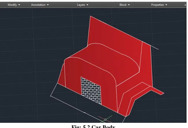
Car body
Fig: 5.2 Car Body
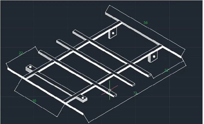
Chassis arrangement
Copyrights © International Journal of Intellectual Advancements and Research in Engineering Computations,
Fig: 5.3 chassis
CHAPTER 6
WORKING OF THE WHOLE SYSTEM
Block diagram
Fig. 6.1 working of whole system
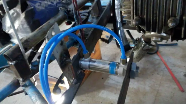
Double acting pneumatic cylinder
When the distance between the vehicle and obstacle falls below the permissible limits which is
Copyrights © International Journal of Intellectual Advancements and Research in Engineering Computations, how long it take for the echo of the sound to reflect
back. This reflected back wave signal is received by receiver, this transmitting and reflecting sound speed is 341m/s. It senses by using this information along with time difference between sending and receiving the sound pulse to determine the distance to an object.
Distance= Time × speed of sound/ 2
After detecting an object the sound wave signal transmit to ardunio microcontroller which consist of AT MEGA 328 IC with LCD display. The distance between and vehicle is being shown in a display after processed by control unit. The controlled signal in the form of electrical signal transfers to solenoid valve which acts as a transducer to allow the passage of compressed air to the double acting pneumatic cylinder.
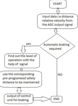
Fig. 6.2 Flow chart
The compressed air from the compressor at the pressure of 5 to 7bar is passed through a pipe connected to the Solenoid valve with one input. The Solenoid Valve is actuated with Control Timing Unit. The Solenoid valve has two outputs and one input. The air entering into the input goes out through the two outputs when the timing control unit is actuated.
Due to the high air pressure at the bottom of the piston, the air pressure below the piston is more than the pressure above the piston. So these moves the piston rod upwards which move up the effort are, which is pivoted by control unit. This force acting is passed on to punch/rivet which also moves downwards.
Copyrights © International Journal of Intellectual Advancements and Research in Engineering Computations, hydraulic brake which apply it mechanism to the
stop vehicle.
The operating principle of solenoid valve:- If the solenoid valve is activated, the compressed air passes to the double Acting Pneumatic Cylinder.
The compressed air activates the pneumatic cylinder and moves the piston rod. If the piston moves forward, then the braking arrangement activated.
The braking arrangement is used to brake the wheel gradually or suddenly due to the piston movement. The braking speed is varied by adjusting the valve is called “FLOW CONTROL VALVE” .The compressed air drawn from compressor in our project. The compressed air flow through the Polyurethane tube to the flow control valve. The flow control valve is connected to the solenoid valve as mentioned in the block diagram.
Advantages
It able to Increase the sureness in braking system.
Braking system able to give fast response.
System able to increase the pre-crash safety.
System able to provide more safety to the passengers.
System plays an important role to save human life.
Life in road accidents.
Free from wear adjustments.
Less skill drives is sufficient to operate.
It gives very simplified operations.
Installation is simplified.
Limitations
System has few limitations in densely traffic road.
System has no provision to prevent and cure the accidents from rear side of vehicle.
Maintenance will be more due to the number of electrical and pneumatic components.
Applications
This system may be applicable in all types of light vehicles like cars, Rickshaws, Tempos.
This system can be successfully installed in the heavy vehicles like buses, trucks, trailers, etc.
Industrial application.
CONCLUSION
In this project we have successfully developed an ultrasonic sensors controlled automatic braking system to avoid forward collision of vehicle. This whole arrangement of automatic braking system is successfully implemented and installed in a vehicle, where the drivers may not brake manually and their will be the automatic application of brake on wheels to stop the car and this advanced safety feature in braking arrangement can reduce a number of accidents to safe human life. This automatic application of brake acts after sensing the obstacle in front of vehicle. This sensor are being installed in front of the vehicle. After going through the number of sensors we found the disadvantage is more in other sensors with respect of ultrasonic sensor. These ultrasonic sensor has large detection range, cheaper and system comprises of a less demanding hardware. This factor, coupled with the fact of lower cost and power consumption of ultrasonic sensors, could facilitate the application and mounting of the system in vehicles, thus helping to improve safety and offere a hassle free driving experience at a reduced cost. The relative application of brake with the measurement of the distance in between vehicle and object in front of it. Our project can be installed in vehicle in automobile sector with a need of some more and advanced high level of programming in its control unit and also by the use of antilock brake mechanism which is not presently used in this project due to its complexity and high expensive rate.
Copyrights © International Journal of Intellectual Advancements and Research in Engineering Computations,
REFERENCES
[1]. J. P. Den Hartog, Advanced Strength of Materials (McGraw-Hill, New York, 1952), TA 405 D4, 1952, Author Name, Conference Name, year etc
[2]. Automobile Engineering by R.B.Gupta [3]. Machine design R.S. Khurmi
[4]. Work shop technology R.K.Jain. [5]. Machine tool design handbook. [6]. www.google.com/ultrasonicsensor
[7]. http://education.rec.ri.emu.edu/content/electronics/doe/ultrasonic sensor [8]. http://wikipedia.org/wiki/ATmega328
[9]. http://wikipedia.org/wiki/solenoidvalve [10].http://www.youtube.com